To The Owner/Operator
Off-the-road tires are expensive pieces of equipmentThey are engineered and built with massive strength to support today’s equipment. This equipment is carrying ever increasing heavier loads at higher speeds and over longer dis-tances than ever before.
Years of research and development have resulted in tires that can offer long service lives under these conditions. High strength carcasses have been developed to offer more load carrying capacity. New, tougher, higher quality components have improved durability. Improved rubber technology has helped to improve carcass durability, tread wear and hazard resistance ability.
Still, there is a limit to the abuse and punishment any tire will take. Too many end up on a scrap pile because operators ignore common sense driving and operational practices. Others go out of service prematurely because they were not properly maintained. This manual, based on long term, extensive OTR field experience and practice, is designed to provide the information needed to help achieve maximum service life for both the end user and the equipment manufacturer. If followed, these recommendations will also help lower ton mile or tonne kilometer costs, improve equipment productivity and promote operating profits.
This Booklet Applies To Earthmover Tires And
Their Applications Only. It Does Not Apply To
CONTENTS
Section I - Maintenance and Operations
Construction Features ... 4
Basic Factors in Tire Maintenance...5
Tires and Operating Conditions ...7
Project/Mine Manager and Job Superintendent Responsibilities ...7
Engineering Department Responsibilities...7
Operations/Production Department Responsibilities ...8
Conscientious Operation by Drivers ...10
Shovel/Wheel Loader Operators ...10
Loader/Dozer Operators ...11
Grader Operators ...11
Watertruck or Wagon Operators ...12
Scraper Operators ...12
Tire Department Responsibilities ...12
Overinflation/Underinflation ...12
Correct Tire Inflation / Proper Tire Inflation...14
Essential Parts of a sound Inflation Maintenance Program...15
Matching of Tires on Rear Duals ...16
How to Calculate Loads and Load Distribution...18
Burned Beads ...19
Repairs ...21
Recapping...22
Handling and Storage of Tires, Tubes and Rims ...22
New Tires...22
Used Tires ...23
Mounted Tires ...23
Tubes ...23
Section II - Procedure for Changing Tires and Tubes
Nitrogen Inflation...24Tire Changing Equipment and Tools...25
Safety Instructions ...26
General...26
Demounting ...26
Horizontal Demounting 51” and Larger HDT Rims...42
Vertical Demounting Tires on a Machine ...44
Demounting Tube-Type Off-The-Highway Tires ...46
Inflation Procedures for Proper Mounting...46
Mounting Off-The-Road Tires ...47
Mounting Bias Off-The-Road Tires on EM Rims...49
Mounting Radial Off-The-Road Tires on EM Rims ...52
Mounting Radial Off-The-Road Tires on Single Piece Wheels...55
Mounting Tires on a Machine ...57
Mounting Tube-Type Off-The-Highway Tires ...60
Section III - Tire Selection for Expected Service Conditions
Tire Selection Criteria ...61Higher vs. Lower Inflation Pressure. ...62
Ton Mile Per Hour (TMPH/TKPH) Requirement ...63
The Work Capability Factor (WCF)...65
Job Conditions ...67
Ballasted Tires ...68
Earthmover Tires Bias Construction – Haulage Service ...71
Bias Construction – Haulage - Scraper Service ...72
Bias Construction – Dozer/Loader Service ...73
Bias Construction – Grader Service. ...75
Bias Construction – Mine Service ...76
Bias Construction – Port and Container Service ...76
Radial Construction – Scraper Service ...77
Radial Construction – Articulated Dump Truck Service ...78
Radial Construction – Haulage Service ...79
Radial Construction – Dozer/Loader Service...80
Radial Construction – Loader/Underground Mine Service ...82
Radial Construction – Mobile Crane Service...82
Radial Construction – Grader Service ...83
Section IV - Load and Inflations For Goodyear Off-The-Road Tires
Index ...84Basic Design
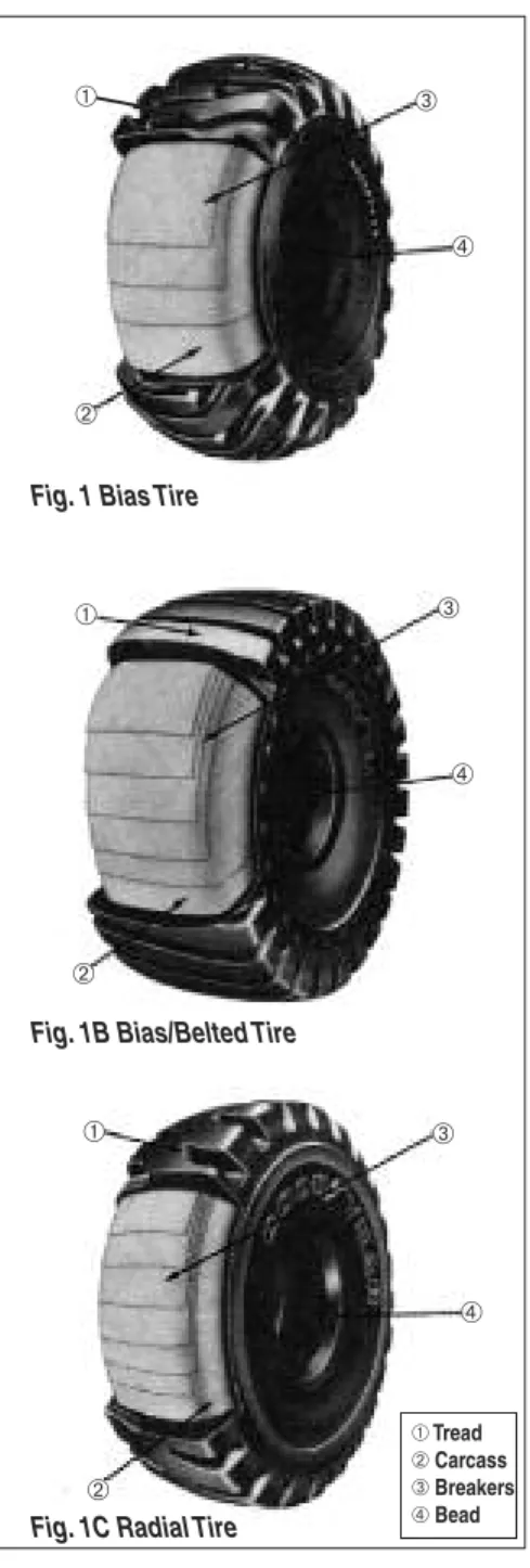
Earthmover tires are produced in three basic constructions:
• Bias • Bias/Belted • Radial
All share a common nomenclature. Tread
The part of the tire in contact with the ground. It must provide traction, long wear and cut resistance. The tread depth and de-sign vary based on site and application. Carcass
Contains the inflation medium. The greater its strength, the greater the pressure it can hold. Bias and bias/belted tire car-casses use many angled plies of fabric to achieve strength. Radials have one ply of steel wire.
Breakers (Belts)
These are placed between the tread and carcass. They help to join these parts. They also distribute road shock to protect the carcass. In bias/belted and radial construc-tions, they control the diameter of the tire. They also impart superior tread impact and penetration resistance.
Bead
Bundles of high tensile steel wire. They an-chor the tire to the rim. Bias and bias/belted tires may have several bead bundles. Radials have one large bead
bun-SECTION 1
Construction Features
Fig. 1 Bias Tire
forms a barrier to protect the carcass from the weather.
Inner Liner
A specially formulated rubber compound in-side the tire that minimizes permeation. It works with the rim and O-ring to contain the inflation medium in tubeless designs.
Deflection
Many people think that deflection de-scribes the bulge at the bottom of a loaded tire. Actually, this bulge occurs as a result of deflection.
Deflection really describes the change in the tire’s radius when a normal load is ap-plied. The radius is measured from the cen-ter of the axle/hub to the ground (See Figure 2, above).
Unloaded Radius is measured with no weight on the tire. The tire is mounted on a rim and inflated to working pressure. The tire is stood and supported so the tread
Static Loaded Radius is measured with the weight of the vehicle and payload on the tire. Static means that the tire is standing still.
The deflection is the difference between the Unloaded Radius and Static Loaded Radius. This is the same distance that the axle lowers when the vehicle is fully loaded.
Deflection is extremely important. Engi-neers design tires to operate at a certain per-centage of deflection. Operating with too much deflection reduces tire life.
Basic Factors Tire Maintenance
UNDEFLECTED (Zero Load) NORMAL DEFLECTION (Rated Load/Inflation) OVERDEFLECTION (Overload and/or Underinflation)
pressure for the load, deflection will be within design limits.
Loading a tire above the specified limit will result in overdeflection.
Inflating a tire above the specified limit will result in underdeflection.
WARNING
Overinflation and or overloading can lead to a tire explosion. This can lead to death, serious injury or property damage. Do not overinflate or overload OTR tires.
For a given tire size, inflation pressure de-termines how much load can be carried (the inflation medium can be air or nitrogen). THE MOST IMPORTANT AND CRIT-ICAL PART OF TIRE MAINTENANCE IS MAINTAINING PROPER INFLA-TION PRESSURE.
Loads
The inflation pressure carries the load. The tire’s pressure capacity is determined by its carcass strength.
Carcass strength is indicated by a ply rat-ing (PR) for bias and bias/belted tires. Sym-bol or Star Ratings are used to indicate radial tire strength (symbol and star mean the same thing).
Some Off-the-road tires are marked with Load Indexes and Speed Symbols. A Load Index is a numerical code associated with the maximum load a tire can carry at the speed indicated by the Speed Symbol under specified service conditions. A Speed Sym-bol indicates the maximum speed that the tire was designed to operate under
speci-A2 5 mph 10 kmph
B 30 mph 50 kmph
E 43 mph 70 kmph
NOTE: none of the terms (PR, Symbol, Star, LISS) indicate the actual number of plies. There are factors other than inflation pres-sure which affect tire load capacity. Larger tires (with larger internal air volumes) can carry higher loads at the same pressure. Load capacity also varies with speed. The tire standards associations (T&RA, ETRTO and JATMA) publish tables of maximum loads at specified speeds. These tables correspond to: • 30 MPH (50 KMPH) for scrapers, trucks. • 25 MPH (40 KMPH) for graders. • 5 MPH (10 KMPH) for dozers, loaders.
• Drive-away speeds for roading
equipment.
Operators sometimes overload tires. They are willing to sacrifice tire performance for fewer trips or higher production (bigger loads).
leads directly to a higher cost per ton mile or kilometer.
Overloading may lead to premature tire failure. If inflation pressure is not adjusted to heavier loads, tires will become unser-viceable due to:
• Tread and ply separation.
• Disintegration of the carcass and inner liner (fatigue).
• Radial sidewall cracking. • Excessive bead chafing.
Overloads with the inflation adjusted to
compensate may exceed the carcass
strength. This will result in: • Impact breaks and cuts. • Rapid wear.
• Fabric fatigue (loss of nylon cord or steel cables strength).
Tires and Operating Conditions
Tires represent one of the major direct ex-penses in off-the-road (OTR) equipment operations.
Regular maintenance will help OTR tires last longer. Longer life translates directly to a lower cost per ton-mile.
Every OTR project should have a tire maintenance program. The program should be overseen by a team which includes members from:
• Project Management /Job Superintendent. • Engineering Department Representative. • Operations/Mining Department. • Maintenance Department Representative.
Project or Mine Manager and Job Superintendent Responsibilities
Successful tire cost management and con-trol begins with top management. Their involvement in the program will em-phasize its importance. They are also in the best position to anticipate changes in tire requirements.
Changes often occur as a project progresses. For example, hauls may get longer. Higher speeds or heavier loads may be required to maintain production. These may require a change in tires or equipment used. A keen, dedicated, cost conscious, tirewise manager or superintendent will be aware of these ongoing changes. Appropriate tires and equipment can then be ordered as needed.
Engineering Department Responsibilities
Haulroad design plays an important role in tire cost control. Both tire wear and hazard exposure can be minimized by proper de-sign. This is especially true on larger proj-ects where roads are used for a long time. Layout and surface condition of the haulroad affect tire life.
Steep grades, sharp turns, poor supereleva-tion increase tire slippage resulting in fast, abrasive tread wear.
Imbedded or loose rocks increase tread cut-ting, sidewall cutcut-ting, and impact break haz-ards. They often lead to speed restrictions which reduce production. Equipment break-down and maintenance costs also increase.
Poor drainage leads to mud and chuck holes. These result in tire spinning, fast tread wear, cuts and increased vehicle fuel usage.
The cost of equipment and labor to main-tain haulroads is significant. However, the cost of delays and tire and equipment re-pair is far greater.
Permanent haulroad criteria should be: 1) Maximum grade not to exceed 7%. 2) Road width to allow two trucks to pass
without spillage. A two lane road should be 3.5 times the widest vehicle. A three lane road 5.0 times the widest vehicle.
3) Road crown, slope or crossfall as flat as possible and still drain. Typical road crown is 2%- 4% (2.5”-5.0” drop per 10’ of lane width/6.4 cm-12.7 cm drop per 3.0 meters of lane width).
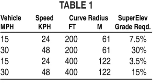
Vehicle travel speed affects the need for superelevation more than curve radius. Table 1 shows the effects of different speeds and radii on superelevation requirements.
TABLE 1
Vehicle Speed Curve Radius SuperElev
MPH KPH FT M Grade Reqd.
15 24 200 61 7.5%
30 48 200 61 30%
15 24 400 122 3.5%
30 48 400 122 15%
In actual practice, haulroad superelevation seldom exceeds 4-5%. This minimizes top dressing flow in rainy or wet operating conditions.
In addition, site size, topography and ground conditions often restrict curve radii. Reduced speed on curves is the most prac-tical way to minimize centrifugal side forces on tires.
The U.S.A. Department of the Interior
publication, Design of Surface Mine
Haulage Roads Bureau of Mines Informa-tion Circular 8758, contains addiInforma-tional in-formation on mine/project haulage road design.
Operations Department Responsibilities
The people who operate equipment play a very key role in how well tires perform. Driver/operator education should include more than how to drive. Drivers who learn and follow tire procedures to identify and avoid tire obstructions help reduce tire costs. These rules include:
2) Keep front windshield, headlights and rear view mirrors clean. This provides good visibility needed to avoid hazards. 3) Check to be sure rear axle rock ejectors are in place and working properly (Fig. 6). Remove rocks lodged between dual tires (Fig. 7).
Fig. 6.
5) Never turn front steering axle tires when the vehicle is standing. This cre-ates very high stress and sheer forces within the tires.
6) Keep off windrows. These are often pres-ent when haulroads are being graded. 7) Do not drive on the berm of the road.
Obstructions are often present. 8) Do not drive over spillage. Spillage can
damage tires. Report it so that it can be cleaned up (Fig. 8).
Fig. 8.
9) Do not drive or back over rocks at shovel or dump areas. (Fig. 9)
11) Reduce speed in areas where underfoot conditions continuously change. Con-ditions in shovel and dump areas change with each load. The condition of secondary roadways is unpredictable.
Conscientious Operation by Drivers
Careful drivers avoid road obstructions that cause cuts and impact breaks. They do not spin drive wheels and cause excessive tread wear.
Good drivers see that mechanical problems are corrected promptly. This includes cor-rect front axle alignment, corcor-rect strut set-tings, no loose or broken springs and no grabbing brakes.
Good drivers regularly check for leaky grease fittings. Oil and grease can causes rapid deterioration of tires.
Good drivers check rims and flanges regu-larly. Bent, chipped, broken or improperly sized flanges strain the bead. Rust, oil or grease on rim assemblies leads to rubber de-terioration which will lead to a shorter service life.
Check tires for damage due to machine ob-structions. Spring clips, fender bolts and other components may clear tires in nor-mal service. Under unusual operating con-ditions, vehicle body movement may cause contact with tires. Cutting or abrasion can result. Dry, caked mud and wedged rocks are also tire hazards.
Fig. 11. Grease and oil are highly damaging to tires.
Fig. 12. A machine obstruction takes a bite out of this tire tread at each revolution.
op-1) Do not overload haulage trucks. 2) Properly center load in bed of truck.
This distributes the load on the wheels correctly and reduces spillage. (Fig. 13)
Fig. 13. Correct truck payload positioning.
Fig. 13a. Incorrect truck payload positioning
3) Properly mate dragline, shovel or wheel loader to trucks being loaded. Excessive spillage is caused when loading equip-ment is too large for the truck (Fig. 13b). Loading different size trucks with the same shovel almost always creates spillage.
4) Station a cleanup dozer at each loading area. Its responsibility is to immediately clear any spillage that does occur. It should also help keep the area as level as possible.
Loader/Dozer Operators
1) Travel slowly between work locations. Thick, heavy loader/dozer tires quickly generate internal heat. This heat dissi-pates slowly. Excess heat can result in tread separation.
2) Use ballast at recommended fill levels where recommended (See page 68 for additional discussion).
3) In load and carry operations, do not ex-ceed tire’s Work Capability Factor (WCF) (See page 65 for additional dis-cussion).
4) Avoid tire spin. Use hydraulics to crowd into the bank or pile.
5) Use bucket to clear a path or level the surface. This will provide smooth, clean footing for the dozer and other vehicles. 6) Bucket should be wider than the out-side-to-outside width of tires on front axle. This will prevent or minimize damage to the sidewalls. Loader wings should be added to help prevent tire damage.
Grader Operators
1) Patrol haulroads and clean up spillage. Main roads where haulage speeds are highest should get the most attention. Two graders should work roads where haulage vehicles are wider than a single grader blade.
3) Create and maintain road crown to pro-vide proper drainage.
4) Fill depressions and dips in the road. This will eliminate excessive tire de-flection on high speed haulage vehicles.
Watertruck or Wagon Operators
Limit watering to control dust.
1) Do not overwater haulroads or work areas. This can lead to unnecessary cuts in tire treads and sidewalls.
• Water acts as a lubricant for rubber. • Wet rubber cuts more easily than dry
rubber.
2) Some watering benefits grading opera-tions.
3) Excessive watering of hard packed, smooth surfaces is a safety hazard. Ve-hicle control/safety is reduced on a slick, wet road surface.
Scraper Operators
1) Avoid tire spinning during loading. If a scraper is not designed for self-loading, wait to be push loaded.
2) Dead stick loading minimizes tire spin. It is essential where ripped rock or rock/earth material is being loaded. 3) Avoid sharp turns.
Never make sharp turns while being push loaded.
Rear tires can be cut and destroyed by the blade of a push dozer. Use a straight not a
5) Check for and remove any rocks lodged between vehicle frame and between rear duals.
Tire Department Responsibilities
The most important item in a tire mainte-nance program is a sound, regularinflation maintenance program.
Inflation supports and carries the load. In-flation must be maintained as specified for the load and service condition.
Tires are designed and built to deflect in service.
Inflation pressures are established to assure tires deflect properly. The pressures re-quired vary with the load, speed and type of service. When inflation pressure is too high or too low, the tire does not deflect within design limits. Tires deteriorate quickly under these conditions.
Generally, low speed off-the-road opera-tions allow heavier loads at a given
infla-tion. At high speeds, loads must be
decreased.
Recommended loads and inflations should always be the norm.
Overinflation
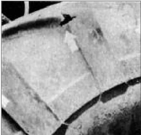
Overinflation results in high cord stress even when the tire isn’t overloaded. Stress reduces resistance to loss of inflation from impacts. It also increases the risk of rock cutting. The problem is made worse by poorly maintained haulroads or spillage. Figures 14 and 15 show typical overinfla-tion damage.
Fig. 14.This break resulted from a severe blow while overinflated.
Fig. 15. Rapid air loss like this occurs frequently when tires are overinflated and suffer an impact.
Underinflation
An underinflated tire will deflect too much leading to excessive sidewall flexing. Underinflation typically results in:
• Irregular or uneven tread wear. • Sidewall radial cracks. • Ply separation.
• Loose or broken cords inside the tire.
• Fabric carcass fatigue. (Fig. 16)
In soft soil, the tire makes an impression. The impression cradles the tire and reduces excess deflection. Inflation can be reduced. Tires operated on hard surfaces do not re-ceive this support. They have to control deflection by inflation pressure. Higher pressures are required.
Indirect, but important, advantages of lower inflation pressures include:
• Better flotation. • Better traction.
• Better resistance to cutting and im-pact breaks.
Fig. 16. Fig. 17.
Loose or broken cords can result from se-vere underinflation.
Radial cracks indicate continuous underin-flation and/or overload operation. (Fig. 17) Continuous operation results in heat buildup in a tire. The hot air expands as a result of the increase in temperature. The tire’s carcass restricts this expansion so pres-sure increases.
In normal off-the-road operation this does not cause deterioration. The pressure be-comes stabilized when internal heating is balanced by external cooling.
NOTICE
Don’t bleed hot OTR tires to correct buildup of air pressure.
Bleeding air pressure will result in danger-ous underinflation. As the tire cools at the end of the day, inflation pressure will drop. The tire will be seriously underinflated at the start of the next shift or day.
Even if the tire is operated through the night, underinflation will occur. Cooler night air will cause the tire to run cooler. Inflation pressure will drop. The tire will suffer excessive deflection and flexing. Damage is inevitable.
Bleeding tire pressure actually begins a vi-cious cycle. Reduced pressure causes in-creased deflection and flexing. These generate heat. Pressure builds up again. The tire is bled to reduce pressure and the cycle repeats. It continues until a complete tire breakdown results.
Proper attention to tire inflation, loads and speeds is the best prevention of tire related problems. These factors need especially careful attention in hot weather.
Correct air pressure only when tires are at ambient temperatures.
Correct Tire Inflation:
1) Assures load carrying ability.
2) Avoids damage due to low or run-flat operation. Carcass fatigue, (tube-less) liner failure and radial cracks are the most common signs of damage. 3) Reduces tread separation due to
overde-Incorrect Inflation
Underinflation results in irreversible dam-age such as:
1) Carcass fatigue. 2) Tubeless liner failure.
3) Tread, ply or bead area separation. Overinflation can be as serious as underin-flation:
1) Overinflation overstresses the tire car-cass.
2) It reduces the tire’s ability to envelope irregular objects in the travel path. 3) It causes a loss of traction.
4) It makes tires more vulnerable to spin cuts and shock load damage.
5) It reduces flotation in soft ground. 6) It produces a hard ride and vehicle
vi-bration. This contributes to: • Payload spillage.
• Poor vehicle handling. • Operator fatigue.
Proper Tire Inflation Procedures
Recommended inflation pressures are always based on a cold reading. A cold tire is one: 1) That has been idle at least 24 hours. 2) Has reached ambient temperatures. Proper inflation for each wheel position should be determined. Ideally, this is based on actual tire loads determined by an on site weight study.
Inflation pressure recommendations vary with the type of service. The type of serv-ice also determines the operating speeds:
• Haulage units (earthmoving, min-ing, loggmin-ing, etc.): 30 MPH/50 KPH maximum speed.
• Dozer/loader units (shovels, mining cars, loaders, etc.): 5 MPH/10 KPH maximum speed.
• Road graders: 25 MPH/40 KPH maximum speed.
Special service conditions also impose speed limits based on tire load and con-struction. These special applications in-clude compactor, sand, straddle carriers, driveaway and intermittent highway use. Load and inflation tables for all types of service are in the back of this book.
Essential Parts of a Sound Inflation Maintenance Program
1) Cold inflation checks and adjustments should be made once a week. Hot checks should be made daily.
2) Never bleed air from a hot tire to cor-rect pressure. Normal equipment
oper-ation causes inflation pressure to
increase. A hot pressure increase up to 20% is acceptable.
If excessive pressure is present, find and fix the cause. Bleeding air will result in serious underinflation and tire damage. 3) Record inflation pressure every time it is checked. Records provide informa-tion that can be used to detect problems and schedule preventive maintenance. 4) Accurate pressure gauges must be used. Service gauges must be calibrated with
• Press the valve core briefly and re-lease a small quantity of air. This cleaning procedure will help assure an accurate reading and prevent damage to the gauge.
6) Use a valve cap on every valve. It acts as the primary air seal. It also helps to pre-vent dirt, dust and water damage to the core.
7) Check spuds, stems and extensions. Be sure all joints are tight and secure to avoid leaks in service.
8) Use valve extensions or hosing for easy access for inflation checks.
9) Compressors:
• Must have a minimum, capacity of 150 PSI (10.0 Bar).
• Compressors must have water trap assemblies to prevent moisture in-side tires.
• Moisture can: – rust rim parts.
– plug valve stems with rust from rims or ice crystals.
– reduce pressure gauge life and accuracy.
– complicate dismounting proce-dures.
• bead seat areas. • flanges.
• O-ring and lock-ring grooves. • lock ring.
Bare metal must be painted or coated with rust inhibitor.
If necessary, sandblast components to bare metal and paint with rust preven-tative paint.
Clean components are easier to mount. They also allow a more thorough in-spection for stress cracks, broken welds and other damage.
12) Store rim components in a dry area to prevent rust and corrosion.
• Separate components for storage (don’t store assembled rims). • Be sure components are properly
matched before mounting tires. 13) The use of nitrogen inflation is
rec-ommended (See page 24). • It reduces rim corrosion.
• It reduces the risk of auto-ignition (tire explosion) from an external heat source. These include: vehicle fires, hot brakes or lightening strikes. To be effective, nitrogen must be used for all maintenance refills.
Hot Inflation Checks
When vehicles operate around the clock, cold inflation checks may not be possible. A hot tire correction factor can be deter-mined by experiment:
• Check as many tires as possible
This average difference should be added to the recommended inflation pressure for tires in constant operation.
A tire that shows a significant variation from the average pressure could have a problem. The vehicle should be stood down until the cause can be determined. N
NOOTTEE:: Cold inflation checks should be done at every opportunity. These include holiday and weekend shutdowns or regular vehicle maintenance periods.
Matching of Duals
Tire assemblies operated as a dual pair must: • Have the same outside diameter
(Within variation listed below). • Be from the same manufacturer. • Be of the same type (industry code). • Be of the same construction (both
bias or both radials).
Bias and radial constructions must never be mixed on dual assemblies.
Tires on dual assemblies must match in size. If they do not, they will not carry equal shares of the load. The larger tire will carry a greater load. It will wear faster than its smaller partner. It will also suffer greater stress which makes it vulnerable to damage. The smaller tire will also suffer irregular scuff wear. This will lead to early replace-ment.
In addition to fast wear, mismatching may result in axle breaks and difficult steering. Maximum diameter variation for duals should be:
Circumferential measurement is a more ac-curate guide for larger tires. The circumfer-ence is measured with a steel tape. For
accuracy, tires must be measured mounted on rims and inflated.
European Tire and Rim Technical Organization
(ETRTO)
Located in Brussels, Belgium, this group is very similar to the T&RA. It too sets standards and issues recom-mendations followed by industry sup-pliers. This results in common
dimensional measurements and
load/inflation relationships beneficial to equipment users.
ETRTO data are expressed in metric units. T&RA data are expressed in English and metric units. They are not necessarily identical.
ETRTO data are not formula conver-sions of English units. They are inde-pendent recommendations. They are based on engineering principles and field experience of the group’s mem-bers. When available, ETRTO data are included in the load/inflation tables in this book. However, ETRTO standards do not exist for all sizes. Where a size is not covered, SI (System International) conversion formulas are used.
Tire and Rim Association (T&RA)
This is an organization of technical representatives from all tire and rim equipment manufacturers. Its purpose is to set industry standards/guidelines. Its work has prevented chaos in the sizes and types of equipment available. This makes rims, tubes, valves and other components widely interchange-able. It also gives equipment operators easy access to replacement parts and service.
The Association also establishes load and inflation recommendations. These are used by equipment manufacturers in the design of their machines. The T&RA yearbook contains many references to load and inflation tables. These recommendations are based on the best engineering principles. They have been refined over years of actual field experience. Importantly, they are based on information gathered from the entire industry, not a single manu-facturer.
Japan Automobile Tyre Manufacturers Association (JATMA)
Located in Tokyo Japan this association is similar to T&RA AND ETRTO. It sets standards and issues recommendations that are followed by type and rim manufac-turers. This results in common dimensional measurements and load/inflation
rela-Fig. 18. Scales set and ready for use.
The best method is to weigh the loaded machine one axle at a time.
When this is impractical, tire load can be estimated with the following formulas. They take into account vehicle designs that result in uneven load distribution on the axles.
To use the formulas, you need to know:
1) Empty weight per axle.
2) Weight of payload (estimated if neces-sary).
3) Measurements shown in Fig. 19. In our formula:
A = Distance from front axle to center of payload in inches.
B = Distance from rear axle to center of payload in inches.
C = Wheelbase in inches. F = Empty weight on front axle. R = Empty weight on rear axle.
With this information, the load on each axle can be determined.
Load on
rear axle = (A/C X payload) + R Load on
front axle = (B/C X payload) + F For example, if:
A = 108” B = 132” C = 240” F = 10,000 # R = 8,000 # Payload = 36,000# then Rear Axle Load =
(A/C X Payload + R =
(108/240 X 36,000) + 8,000 =
( .45 X 36,000) + 8,000 =
16,200 + 8,000 = 24,200
and Front Axle Load =
(B/C X Payload + F =
(132/240 X 36,000) + 10,000 =
( .55 X 36,000) + 10,000 =
19,800 + 10,000 = 29,800
Our example also shows that the part of the load on each axle is a percentage of the wheelbase.
In our example, the distance from the cen-ter of the payload to the front axle is 45% of the wheelbase:
108/240 = .45 = 45%
This is the percentage of the load carried by the rear axle.
The distance from the center of the pay-load to the rear axle is 55% of the wheel-base:
132/240 = .55 = 55%
This is the percentage of the load carried by the front axle.
These percentages give us a ratio: 45:55 = 100.
This is important because it applies to any load in that vehicle. Thus, it allows us quickly to calculate the effects of lighter or heavier loads.
Load Distribution on Other Types of Carriers
The formula may be applied to all types of wheeled machines. Some slight changes in description may be needed, however. For example, in a tractor/trailer combination: The wheelbase is the distance from the pivot point to the rear axle.
To determine the weight distribution on the tractor:
The pivot point is the center of the load. The load on the pivot point is the total payload on the tractor.
Burned Beads
WARNING
Burned beads are very dangerous. They can cause a sudden loss of air that can lead to death, serious injury or property damage. These have been reported more than an hour after a vehicle was parked.
Another risk is a loss of inflation long after the machine is parked. When the machine is shut down, cooling air does not circulate. The hot brake quickly transfers heat to the rim base. Air pressure builds and the bead becomes hot and weak. Eventually, an explosive,
The machine should be parked outside, re-mote from all personnel.
DO NOT STAND NEAR A TIRE AND RIM AS-SEMBLY WITH A HOT BRAKE.
Burned beads are usually caused by brake problems. Excessive braking or dragging brakes are the most common source. Excessive braking can result in tempera-tures up to 500º F (246º C). This heat is transmitted through the brake drum to the rim. The rim heats the inside bead and burns it.
The most common is a reduction in com-pressive fit between bead and rim. This causes a leak. If it does not produce a flat tire, it will result in underinflation. An un-derinflated tire will generate more heat. This will lead to ply separation and a loss of strength. Rapid air loss will occur. This most likely will be in the bead or lower sidewall.
Air wicking through the carcass is another problem bead condition. This causes pres-sure to build up within the carcass and a separation of tire components.
Fig. 20. Toe has been burned and chaffed due to burned bead.
After the brake has cooled, the tire can be replaced.
Modern equipment design has made brake overheating rare.
Engine retarders are common. These slow the equipment without excessive braking. Proper training will assure that operators use this feature effectively.
Some machines use wheel coolants. These transfer heat from the bead area. Coolant must be checked regularly and maintained at proper levels.
Most burned bead problems occur with new equipment or new operators. Proper training and a conscious effort to avoid ex-cessive braking can prevent most problems.
Repairs
Both tube-type and tubeless tires can be paired. Regular inspection can detect re-pairable injuries before they become serious. Immediate attention may prevent extensive or costly damage.
Tread and sidewall cuts are a major source of off-the-road tire trouble. Tires should be checked at the start of each shift and dur-ing regular inflation checks. Cuts which extend to or into the belts or cord body must be repaired. The tire must be taken off for repair.
Shallow cuts in the tread can be treated without dismounting tires. Small rocks and dirt will get into these shallow cuts. If neg-lected, the rocks will gradually be pounded or drilled through the cord body.
Clean out cuts with an awl to remove any lodged in or embedded material. Use a sharp, small blade knife to cut a cone-shaped cavity. The cavity should extend to the bottom of the injury. Sides of the cav-ity should slant enough to prevent stones from wedging. Tires with cuts treated in this manner may continue in service and cut growth should be reduced.
All small cuts should be repaired when tires are removed for major cut repairs. Tires with very high hours (greater than 10,000) are not good repair candidates.
Tire repair may be possible, but may not be economical in older tires. The cost of the repair must be justified by the remaining service life.
Fig. 23 Deep tread rock cut – If left unattended will cause cut separation or cut through.
Recapping/Retreading
Both tube-type and tubeless tires can be re-capped.
Recapped tubeless earthmover tires do not require a tube to return to service. A good tire maintenance program will re-sult in tire cost savings. It will also improve tire retreadability for future savings. Some service conditions take too much
life out of the carcass. Retreading should not be considered for tires operated:
• At high speeds. • Overloaded. • Underinflated.
Tires with very high hours (greater than 10,000) should not be retreaded.
The best recapping candidates are tires which had fast tread wear. This occurs at sites with steep grades or abrasive surfaces.
Handling and Storage of Tires, Tubes and Rims
Proper handling and storage will prevent damage to tubeless tires.
Unmounted tires should be shipped and stored vertically. Horizontal storage may compress the beads. This may make initial inflation difficult.
Some new tires are shipped banded to pre-serve their shape. Do not remove bands until tires are ready to mount.
Do not lift tires by the beads. Sharp hooks or forks cut and tear beads. In service, beads may leak at these lifting points.
Foreign material and moisture must be re-moved from the inside of the tire before mounting.
Rims
Tubeless rims are an important part of the air seal in a mounted tire. Do not distort or mutilate rim parts.
Never lift rims by valve holes.
Store O-ring seals in a cool, dry place. Lay flat. Do not stack other materials on O-rings.
Store valves in a clean, cool, dry place.
Tire and Tube Storage
Tires and tubes deteriorate rapidly if im-properly stored.
Improper storage conditions include: • Direct sunlight.
• Heat.
• Air in motion. • Ozone.
• Gasoline and oil. • Dust and dirt.
• Water or moisture inside tires. Even short term storage should avoid ex-posure to these conditions.
Storage time should be minimized by using tires in the order received.
cover. Water and moisture must be kept out of the tire.
If possible, mount on wheels and inflate to 10% of operating pressure. Store ver-tically. Cover with a tarpaulin. 2) Store away from electrical devices such
as motors and switches. These are a source of ozone.
3) Do not store in rooms with or near gasoline or lubricants. Rubber absorbs vapors from these materials and they can cause deterioration.
4) Provide carbon dioxide fire extinguish-ers in tire storage areas.
Used Tires
1) Carefully clean and inspect tires before storage. Make necessary repairs before storage. Repairs to injuries which ex-pose tire cord are especially important. Moisture can get into exposed cord. 2) Observe all storage rules listed for new
tires.
Mounted Tires
1) If tires are stored on a machine, it should be blocked up. Air should be re-leased to 10 psi (.7 bar) or less. If ma-chine cannot be blocked up, check air pressure frequently. Maintain pressure at proper level.
2) Protect each tire with an opaque, wa-terproof cover.
3) Machines resting on tires should be moved once a month. This prevents de-flection strain on only one part of the tire.
4) Do not use paint to preserve tires. If se-vere storage conditions are expected, consult tire supplier for recommenda -tions.
Tubes
1) Store in original package until ready for use. Keep in a cool, dry, draft free area. 2) Used tubes must be removed from the tire. They must be completely deflated, cleaned and folded. Store in a cool, dry, draft free area.
Replacement of off-the-road tires is a diffi-cult job. They are often located in rough, hilly terrain. Most are used in remote geo-graphical locations. Site conditions are usually far from ideal. Proper equipment may not be available.
The procedures in this section describe changing larger size tires. Both ideal and difficult conditions are covered.
The procedures are based on both field and shop experience. They are designed to make the change as easy as possible.
Nitrogen Inflation
Many original equipment manufacturers recommend nitrogen inflation. It helps to minimize the possibility of explosion due to excessive heat from external sources. Typical sources are:
• Vehicle fires. • Excessive braking. • Dragging brakes.
• Welding on rims of mounted tires. • Lightening strikes.
All these can cause the inside of the tire to ignite and burn.
WARNING
An explosion caused by tire auto-ignition is much more violent than other sudden air loss situations.
Serious injuries and death can result from
• An appropriate relief valve.
• A pressure regulator set for no more than 20 PSI (1.5 Bar) over desired in-flation.
• A remote control clip-on chuck. This allows personnel to stand clear of tire/rim assembly during inflation. Proper inflation pressure for tires inflated with nitrogen is the same as for air.
Nitrogen tanks are pressurized to 2200 PSI (152 Bar).
Correct equipment must be used and proper safety precautions taken. Otherwise, an ex-plosion or blowout of the tire/rim assembly could result. This can cause death, serious personal injury and property damage.
There are several other benefits to nitrogen inflation:
SECTION II
Procedure for Changing
Tires and Tubes
Tire Changing Equipment and Tools
Tire changing procedures vary with indi-vidual operators. Certain tools, however, are essential.
1) Heavy equipment jack.
2) Tire tools and irons. These include: • Several irons with dished or spoon
shaped ends. • Crowbar.
• Heavy duty rubber or wood mallet or lead or babbit hammer.
3) Wheel chucks. 4) Jack stands 5) Air compressor.
6) Service truck. In larger operations, a fully equipped truck can minimize down time. The truck should be equipped with:
• A mounted hoist. The hoist should be strong enough to handle the largest tires.
• An air compressor with a regulator. Models are available which operate off the truck engine or are self pow-ered.
• Large bore/super large bore inflating equipment. This minimizes inflation time.
• Clip-on chucks with remote con-trols. These allow inflation from a safe distance.
GENERAL SAFETY INSTRUCTIONS
The following section of this Manual contains important safety information, including steps necessary to avoid accidents that may result in death, serious injury or property dam-age. Follow all procedures and safety instructions exactly. Wear proper personal protective equipment (PPE).
DEMOUNTING
B
Be
effo
orre
e p
pe
errffo
orrm
miin
ng
g a
an
ny
y sse
errv
viic
ce
e o
on
n O
Offff--T
Th
he
e--R
Ro
oa
ad
d ttiirre
ess,,
rre
ea
ad
d a
an
nd
d u
un
nd
de
errsstta
an
nd
d a
allll ssa
affe
etty
y p
prre
ec
ca
au
uttiio
on
nss.. D
Do
o n
no
ott
m
mo
ou
un
ntt o
orr d
de
em
mo
ou
un
ntt ttiirre
ess w
wiitth
ho
ou
utt p
prro
op
pe
err ttrra
aiin
niin
ng
g..
PRECAUTION
B
Beeffoorree rreemmoovviinngg aannyy rriimm oorr wwhheeeell ccoom m--p
poonneenntt ((ii..ee..,, nnuuttss oorr rriimm ccllaammppss)):: •
• EExxhhaauusstt aallll aaiirr ffrroomm aa ssiinnggllee ttiirree.. •
• EExxhhaauusstt aallll aaiirr ffrroomm bbootthh ttiirreess ooff aa d
duuaall aasssseemmbbllyy..
REASON FOR PRECAUTION
A broken rim part under pressure can blow apart and cause fatal injury. If you remove lugs while tire is under pressure, the assem-bly may fly apart.
R
Reemmoovvee vvaallvvee ccoorree ccoommpplleetteellyy.. TThhiiss wwiillll a
assssuurree aallll aaiirr iiss eexxhhaauusstteedd ffrroomm ttiirree.. •
• RReemmoovvee bbootthh ccoorreess ffrroomm dduuaall a ass--sseemmbbllyy..
•
• RRuunn aa ppiieeccee ooff wwiirree tthhrroouugghh sstteemm ttoo bbee ssuurree iitt’’ss nnoott pplluuggggeedd..
Foreign material may clog the valve stem during deflation.
Ice may form as the air leaves the tire. This can clog the valve stem.
A
Allwwaayyss ssttaanndd cclleeaarr dduurriinngg ddeeffllaattiioonn.. If the assembly bursts, the operator should be far away from the explosive force.
U
Ussee aapppprroovveedd eeyyee pprrootteeccttiioonn.. Protect eyes from dust and dirt when ex-hausting air from tires.
U
Ussee mmeecchhaanniiccaall aaiiddss wwhheenn rreemmoovviinngg h
heeaavvyy rriimm ccoommppoonneennttss..
This will help protect you from injury. A dropped flange can crush a hand or foot. Attempting to grab a falling flange or bead seat can cause serious injury.
D
Deemmoouunnttiinngg ttoooollss aappppllyy hhiigghh pprreessssuurree ttoo
rriimm ffllaannggeess wwhheenn uunnsseeaattiinngg ttiirree bbeeaaddss.. If tool slips, it can fly with enough force tocause severe injury or death. Keep fingers clear. Always stand to one side when you apply pressure.
INSPECTION
PRECAUTIONC
Clleeaann aanndd rreeppaaiinntt rriimmss.. TThhiiss wwiillll ssttoopp c
coorrrroossiioonn.. IItt wwiillll aallssoo mmaakkee iitt eeaassiieerr ttoo m
moouunntt aanndd cchheecckk ccoommppoonneennttss.. C
Clleeaann ddiirrtt aanndd rruusstt ffrroomm lloocckk rriinngg aanndd g
guutttteerr.. A
Aiirr iinnffllaattiioonn eeqquuiippmmeenntt sshhoouulldd hhaavvee aa ffiilltteerr iinn tthhee aaiirr lliinnee.. FFiilltteerr mmuusstt bbee c
chheecckkeedd ffrreeqquueennttllyy ttoo sseeee tthhaatt iitt wwoorrkkss p
prrooppeerrllyy..
REASON FOR PRECAUTION
Parts must be clean for proper fit. This is especially true of the gutter section which holds lock ring in position.
This is important to seat the lock ring properly.
This will prevent moisture from entering the tire and prevent corrosion.
C
Chheecckk rriimm ccoommppoonneennttss ffoorr ccrraacckkss R
Reeppllaaccee aallll ccoommppoonneennttss wwhhiicchh aarree:: • • CCrraacckkeedd • • BBaaddllyy wwoorrnn • • DDaammaaggeedd •
• SSeevveerreellyy rruusstteedd U
Ussee nneeww ccoommppoonneenntt ooff ssaammee ssiizzee aanndd ttyyppee.. RReeppllaacceemmeenntt ppaarrttss mmuusstt nnoott bbee c
crraacckkeedd,, bbrrookkeenn oorr ddaammaaggeedd..
Parts that are cracked, damaged or exces-sively rusted are weakened. Bent or repaired parts may not engage properly.
N
Neevveerr,, uunnddeerr aannyy cciirrccuummssttaanncceess,, a att--tteemmpptt ttoo rreewwoorrkk,, wweelldd,, hheeaatt,, oorr bbrraazzee a
annyy rriimm ccoommppoonneennttss tthhaatt aarree ccrraacckkeedd,, b
brrookkeenn oorr ddaammaaggeedd.. R
Reeppllaaccee wwiitthh ppaarrttss tthhaatt aarree nnoott ccrraacckkeedd,, b
brrookkeenn oorr ddaammaaggeedd.. AAllwwaayyss uussee ppaarrttss ooff tthhee ssaammee ssiizzee aanndd ttyyppee..
Heating may weaken a part. It may then be unable to withstand forces of inflation or operation. This can lead to an incident re-sulting in serious injury or death.
B
Bee ssuurree ccoorrrreecctt ppaarrttss aarree bbeeiinngg aasssseem m--b
blleedd.. C
Chheecckk tthhee ppaarrttss’’ ddiissttrriibbuuttoorr oorr mmaannuuffaac c--ttuurreerr iiff yyoouu hhaavvee aannyy ddoouubbttss..
D
Doo nnoott bbee ccaarreelleessss oorr ttaakkee cchhaanncceess..
Mismatched parts may appear to fit. When the tire is inflated they can fly apart with explosive force. This may lead to serious in-jury or death.
IIff yyoouu aarree nnoott ssuurree aabboouutt pprrooppeerr mmaattiinngg o
off rriimm aanndd wwhheeeell ppaarrttss,, ccoonnssuulltt aann eex x--p
peerrtt..
This may be the tire man who services your fleet. It may be your wheel distributor.
D
Doonn’’tt rreeiinnffllaattee aa ttiirree tthhaatt hhaass bbeeeenn rruunn ffllaatt uunnttiill yyoouu iinnssppeecctt::
• • TTiirree • • TTuubbee • • FFllaapp •
• RRiimm aanndd wwhheeeell aasssseemmbbllyy D Doouubbllee cchheecckk:: • • FFllaannggee((ss)) • • BBeeaadd sseeaatt • • LLoocckk rriinngg • • OO--rriinngg B
Bee ssuurree tthheeyy aarree sseeccuurree iinn tthhee gguutttteerr bbe e--ffoorree iinnffllaattiioonn..
S
Sttaanndd cclleeaarr ooff tthhee ttiirree wwhhiillee iinnffllaattiinngg..
Components can be damaged or dislocated when a tire is run flat or seriously underin-flated. This can lead to an incident result-ing in death or serious injury.
MOUNTING AND INFLATION
PRECAUTION
D
Doonn’’tt hhaammmmeerr bbeeaadd sseeaatt rriinnggss oorr ootthheerr c
coommppoonneennttss wwhhiillee ttiirree iiss iinnffllaatteedd.. YYoouu m
maayy ttaapp tthhee lloocckk rriinngg wwhheenn iinnffllaattiioonn bbe e--g
giinnss wwiitthh aa rruubbbbeerr oorr sshhoott hhaammmmeerr ttoo iin n--ssuurree iitt iiss pprrooppeerrllyy sseeaatteedd..
REASON FOR PRECAUTION
If parts are improperly installed they may fly apart with explosive force.
D
Doouubbllee cchheecckk ttoo bbee ssuurree aallll ccoommppoonneennttss a
arree pprrooppeerrllyy sseeaatteedd bbeeffoorree iinnffllaattiinngg..
If parts are improperly installed they may fly apart with explosive force.
IInnffllaattee iinn aa ssaaffeettyy ccaaggee.. UUssee ssaaffeettyy cchhaaiinnss o
orr eeqquuiivvaalleenntt rreessttrraaiinniinngg ddeevviicceess dduurriinngg iinnffllaattiioonn..
Parts can fly apart with explosive force dur-ing inflation.
D
Doonn’’tt iinnffllaattee ttiirree bbeeffoorree aallll ccoommppoonneennttss a
arree pprrooppeerrllyy iinn ppllaaccee.. P
Pllaaccee iinn ssaaffeettyy ccaaggee oorr uussee cchhaaiinn sslliinngg a
anndd iinnffllaattee ttoo aapppprrooxxiimmaatteellyy 55 PPSSII ((..55 B
Baarr)).. RReecchheecckk ccoommppoonneennttss ffoorr pprrooppeerr a
asssseemmbbllyy..
IIff aasssseemmbbllyy iiss nnoott pprrooppeerr aatt aapppprroox xii--m
maatteellyy 55 PPSSII ((..55BBaarr)) ccoommpplleetteellyy ddeeffllaattee ttiirree ((bbootthh ttuubbee--ttyyppee aanndd ttuubbeelleessss)) aanndd ssttaarrtt oovveerr..
IInnffllaattiioonn ttoo rreeccoommmmeennddeedd ooppeerraattiinngg p
prreessssuurree sshhoouulldd bbee ddoonnee oonn tthhee vveehhiiccllee.. N
Neevveerr hhaammmmeerr oonn aa ffuullllyy oorr ppaarrttiiaallllyy iin n--ffllaatteedd ttiirree//rriimm aasssseemmbbllyy..
Properly matched and assembled compo-nents will seat without tapping. If a part is tapped, it or the tool can fly out with ex-plosive force.
N
Neevveerr ssiitt oorr ssttaanndd iinn ffrroonntt ooff aa ttiirree aanndd rriimm aasssseemmbbllyy tthhaatt iiss bbeeiinngg iinnffllaatteedd.. U
Ussee aa cclliipp--oonn cchhuucckk.. UUssee iinnffllaattiioonn hhoossee lloonngg eennoouugghh ttoo ssttaanndd ttoo ssiiddee ooff ttiirree..
N
Neevveerr wweelldd oonn aa ttiirree//rriimm aasssseemmbbllyy.. Heat from welding will cause a sudden rise in pressure. This may result in a powerful explosion.
Deflated tires also can catch fire inside the chamber. Pressure will build up. An explo-sion may occur.
F
Foollllooww ttiirree aanndd rriimm mmaannuuffaaccttuurreerrss’’ rreec c--o
ommmmeennddeedd pprroocceedduurreess ffoorr:: •
• MMoouunnttiinngg •
• DDeemmoouunnttiinngg •
• IInnffllaattiinngg •
• DDeeffllaattiinngg
Failure to do so can result in death or seri-ous injury.
D
Doonn’’tt hhaammmmeerr oonn rriimmss oorr ccoommppoonneennttss w
wiitthh sstteeeell hhaammmmeerrss..
IIff nneecceessssaarryy ttoo ttaapp uunniinnffllaatteedd ccoommppo o--n
neennttss ttooggeetthheerr,, uussee mmaalllleettss wwiitthh ffaacceess ooff:: • • RRuubbbbeerr • • LLeeaadd • • PPllaassttiicc • • BBrraassss
Steel hammers may damage components and cause improper fit.
S
Sttaanndd cclleeaarr wwhheenn uussiinngg aa sstteeeell ccaabbllee oorr c
chhaaiinn sslliinngg..
The cable or chain may break. If it does it can lash out and cause serious injury.
M
Miixxiinngg ppaarrttss ooff oonnee ttyyppee rriimm wwiitthh tthhoossee o
off aannootthheerr iiss ppootteennttiiaallllyy ddaannggeerroouuss.. A
Allwwaayyss cchheecckk DDOOTT cchhaarrtt oorr mmaannuuffaac c--ttuurreerr ffoorr aapppprroovvaall..
Mismatched parts may appear to fit. When the tire is inflated they can fly apart with explosive force.
N
Neevveerr iinnttrroodduuccee aa ffllaammmmaabbllee ssuubbssttaannccee iinnttoo aa ttiirree bbeeffoorree,, dduurriinngg oorr aafftteerr mmoouun ntt--iinngg..
This is unsafe and could result in: • Fire
• Internal tire damage • Rim damage
• Potentially dangerous vapors. Any of these conditions can cause death or serious personal injury during mounting and inflation.
OPERATION
PRECAUTIOND
Doonn’’tt uussee uunnddeerrssiizzeedd rriimmss.. U
Ussee rreeccoommmmeennddeedd rriimm ffoorr ttiirree.. CChheecckk G
Gooooddyyeeaarr ccaattaallooggss ffoorr pprrooppeerr ttiirree//rriimm m
maattcchhiinngg..
REASON FOR PRECAUTION
Excessive overload can cause damage to the tire and rim assembly.
D
Doonn’’tt oovveerrllooaadd oorr oovveerriinnffllaattee ttiirree//rriimm a
asssseemmbblliieess.. C
Chheecckk wwiitthh yyoouurr ttiirree aanndd rriimm mmaannuuffaac c--ttuurreerr iiff ssppeecciiaall ooppeerraattiinngg ccoonnddiittiioonnss aarree rreeqquuiirreedd..
Excessive overload due to undersized rims can cause damage to the tire and rim as-sembly.
N
Neevveerr rruunn aa vveehhiiccllee oonn oonnee ttiirree ooff aa dduuaall a
asssseemmbbllyy..
This will exceed the carrying capacity of the single tire and rim. Operating a vehi-cle in this manner can result in damage to rim and tire.
N
Neevveerr uussee aa ttuubbee iinn aa ttuubbeelleessss ttiirree wwhheerree tthhee rriimm aasssseemmbbllyy iiss ssuussppeecctteedd ooff lleeaakkiinngg..
Loss of air pressure warns you of a potential rim failure due to fatigue cracks or other fractures. This indicator is lost when tubes are used with leaking rims. Continued use may cause the rim to burst with explosive force.
A
Allwwaayyss iinnssppeecctt rriimmss aanndd wwhheeeellss ffoorr ddaam m--a
aggee dduurriinngg ttiirree cchheecckkss..
Early detection of rim damage or wear may prevent an accident.
N
Neevveerr mmooddiiffyy aa rriimm wwiitthhoouutt aapppprroovvaall ffrroomm tthhee mmaannuuffaaccttuurreerr..
N
Neevveerr hheeaatt,, wweelldd oorr bbrraazzee aa rriimm.. A
Allwwaayyss rreemmoovvee tthhee ttiirree ffrroomm tthhee rriimm bbe e--ffoorree sseerrvviiccee..
Modification or heating of the rim or one of its parts can weaken it. It may not with-stand inflation or operation forces.
D
Doonn’’tt lleett tthhee bbrraakkeess bbeeccoommee oovveerrhheeaatteedd.. A
Avvooiidd aabbuusseess tthhaatt ccaann oovveerrhheeaatt bbrraakkeess.. T
Thheessee iinncclluuddee:: •
• DDrraaggggiinngg ooff bbrraakkeess •
• SSppeeeeddiinngg •
• PPoooorr bbrraakkee aaddjjuussttmmeenntt •
• OOvveerrllooaaddiinngg C
Clleeaarr tthhee aarreeaa iiff eexxcceessssiivvee bbrraakkee hheeaatt iiss ssuussppeecctteedd.. WWaarrnniinnggss iinncclluuddee::
•
• TThhee ssmmeellll ooff bbuurrnniinngg rruubbbbeerr •
• TThhee ssmmeellll ooff hhoott bbrraakkeess W
Waaiitt aatt lleeaasstt oonnee hhoouurr bbeeffoorree aapppprrooaacch h--iinngg mmaacchhiinnee..
C
Caarreeffuullllyy ffoollllooww mmaannuuffaaccttuurreerr’’ss rreeccoomm --m
meennddaattiioonnss ffoorr:: •
• OOppeerraattiinngg pprraaccttiicceess •
• UUssee ooff rreettaarrddeerrss •
• BBrraakkeess •
• BBrraakkee mmaaiinntteennaannccee
An explosion can occur when a tire is ex-posed to extreme temperatures from exter-nal sources. This can cause death, serious personal injury or property damage.
The risk of explosion is greatest soon after the vehicle is stopped.
IIff vveehhiiccllee wwhheeeellss hhaavvee bbeeeenn ddeessiiggnneedd ttoo c
coonnttaaiinn wwhheeeell ccoooollaanntt,, nneevveerr ooppeerraattee v
veehhiiccllee wwiitthhoouutt ccoooollaanntt.. A
Allwwaayyss uussee tthhee mmiixx aanndd aammoouunntt ooff ccooooll --a
anntt rreeccoommmmeennddeedd bbyy tthhee mmaannuuffaaccttuurreerr..
An explosion can occur when a tire is posed to extreme temperatures from an ex-ternal source. This can cause death, serious injury or property damage. Wheel coolant helps keep operating temperatures down. It must be used where recommended.
SERVICING TIRE AND RIM ON MACHINE
P
Puutt hhaarrddwwoooodd bblloocckkss uunnddeerr jjaacckk.. U
Ussee bblloocckkss rreeggaarrddlleessss ooff hhooww hhaarrdd oorr ffiirrmm ggrroouunndd aappppeeaarrss ttoo bbee..
A
Allwwaayyss ccrriibb uupp aa vveehhiiccllee wwiitthh bblloocckkss oorr a
a jjaacckk ssttaanndd
Machine may shift and slip off jack. This can cause death or serious injury.
PRECAUTION
B
Blloocckk ttiirree aanndd wwhheeeell oonn ooppppoossiittee ssiiddee ooff m
maacchhiinnee bbeeffoorree ppllaacciinngg jjaacckk iinn ppoossiittiioonn..
REASON FOR PRECAUTION
Machine may shift and slip off jack. This can cause death or serious injury.
D
Doonn’’tt hhaammmmeerr ttoo ddrriivvee aa ttiirree aanndd rriimm a ass--sseemmbbllyy oovveerr aa ccaasstt ssppookkee wwhheeeell.. D
Deeffllaattee aanndd eexxaammiinnee ttoo ddeetteerrmmiinnee tthhee rreeaassoonn ffoorr iimmpprrooppeerr ffiitt.. LLooookk ffoorr ddiisstto orr--ttiioonn oorr ccoommppoonneennttss nnoott pprrooppeerrllyy lloocckkeedd o
orr sseeaatteedd..
Failure to fit can indicate distorted or in-correctly assembled components.
In either case, the assembly could fly apart if hammered and cause death or serious in-jury.
B
Beeffoorree lloooosseenniinngg nnuuttss oorr ccllaammppss,, aallwwaayyss sseeccuurree aa ttiirree//rriimm aasssseemmbbllyy wwiitthh::
•
• AA sslliinngg •
• TTiirree hhaannddlleerr •
• OOtthheerr ssuuppppoorrtt eeqquuiippmmeenntt C
Coonnssuulltt vveehhiiccllee mmaannuuffaaccttuurreerr ffoorr dde e--ttaaiilleedd iinnssttrruuccttiioonnss oonn rreemmoovvaall ooff ttiirree//rriimm aasssseemmbblliieess..
Unsecured assemblies may fall when fasteners are removed.
D
Doo nnoott,, uunnddeerr aannyy cciirrccuummssttaanncceess,, uussee a
annyy ttyyppee ooff hheeaatt ssoouurrccee oonn aann iinnffllaatteedd ttiirree..
Welding or other heating of an inflated tire/rim assembly can cause an explosion. This can cause death, serious injury or property damage.
Welding or brazing a rim with a deflated tire can cause damage to the tire. When rein-flated, the damaged tire could also explode. Welding or brazing a rim with no tire is contrary to recommendations of rim man-ufacturers. It can cause a structural weak-ness in the rim. This can also lead to failure under inflation or service conditions.
Demounting Procedures
B
Be
effo
orre
e rre
em
mo
ov
viin
ng
g a
an
ny
y rriim
m o
orr w
wh
he
ee
ell c
co
om
mp
po
on
ne
en
ntt::
• Wear proper personal protective equipment (PPE) • Remove the valve core.
• Exhaust all air from the tire.
• Run a piece of wire through the stem to be sure it is not plugged. Exhaust air from both tires of a dual assembly before working on either.
Read safety instructions (pages 26-35) before proceeding. PROCEDURE REQUIRES:
• 2 Goose-necked bead unseating tools.
• Rubber lubricant.
• Rubber, plastic, lead or brass faced mallet.
Photo 1
Before removing any rim or wheel compo-nent:
• Wear proper personal protective equipment (PPE)
• Remove the valve core. • Exhaust all air from the tire.
• Run a piece of wire through the stem to be sure it is not plugged.
Exhaust air from both tires of a dual assembly before working on either.
Photo 2
Demounting Instructions
Semi Drop-Center Rims
T
After complete deflation, place assembly on blocks with loose flange side up. Follow steps in order shown.
1. Drive goose-necked end of two tools between tire and flange. They should be about 2-feet (70 cm) apart. (Photo 1)
2a. Pry both tools outward and sideways through an arc of about 70º. (Photo 2) 2b. Leave one tool in position and move second about 5-inches (13 cm) beyond. Pry down and out as above.
2c. Repeat the process until the entire bead is unseated.
Photo 3
3. Stand on sidewall. Use foot to force flange down along rim base. Pry loose lock ring. (Photo 3)
4. Hold side of flange down with hooked end of tool. Grab and remove O-ring from O-ring groove. (Photo 4) 5. Remove side flange. (Photo 5) 6. Turn tire over.
7. Follow steps 1 and 2 to break tire loose from fixed flange side of rim.
8. Lift rim base from tire. (Photo 6)
Read safety instructions (pages 26-35) before proceeding. PROCEDURE REQUIRES:
• 1 goose-neck bead unseating tool • 3 tire irons
• Rubber lubricant
Photo 1
Before working on tire or rim:
• Wear proper personal protective equipment (PPE)
• Remove the valve core. • Exhaust all air from the tire.
• Run a piece of wire through the stem to be sure it is not plugged.
Exhaust air from both tires of a dual assembly before working on either.
After complete deflation, place assembly on blocks with loose flange side up. Follow steps in order shown.
1. Stand on tire. Use goose-neck tool to break bead from wheel flange. 2. Lubricate top tire bead and top flange
area on wheel.
3. Insert two tire irons close together under top bead. (Photo 1)
4. Hold one tire iron down in original po-sition. Hold firmly so it does not fly up and strike you.
Demounting Instructions
Single Piece Rims
(
5. Work 2nd tire iron around wheel until bead is completely demounted. (Photo 2)
• Use standing weight to help push bead into wheel well.
6. Stand tire/wheel assembly up.
• Break bead from second wheel flange.
• Lubricate near tire bead and back flange area on wheel.
• Pull top of wheel out of tire as far as possible. Use foot on bottom of wheel to hold in cocked position. Tire bead should be in wheel well. 7. Force spoon of tire iron between bead
and wheel flange. (Photo 3) Raise tire iron until it is straight up. Hold in po-sition.
8. Position 2nd tire iron 12” to right of first iron.(Photo 4) Force spoon under bead and over wheel flange.
9. Rotate 2nd tire iron 90º. (Photo 5) Lift 2nd tire iron straight up.
10. Hold 1st and 2nd tire irons in one hand so they form a triangle. Position 3rd tire iron 12” to left of first iron. Rotate 3rd tire iron 90º to wheel. (Photo 6) Lift 3rd tire iron straight up.
11. Once bead is over flange, finish de-mounting with one tire iron.
Read safety instructions (pages 26-35) before proceeding. PROCEDURE REQUIRES:
• Hydraulic demounting tool • 2 pry bars
Before removing any rim or wheel compo-nent:
• Wear proper personal protective equipment (PPE)
• Remove the valve core. • Exhaust all air from the tire.
• Run a piece of wire through the stem to be sure it is not plugged.
Exhaust air from both tires of a dual assembly before working on either.
After complete deflation, place assembly on blocks with gutter side up. Follow steps in order shown.
1. Force pry bars under lock ring from op-posite sides. They should be separated by about 10-inches. Push bars in oppo-site directions to pry lock ring out. (Photo1)
NOTE: If lock ring cannot be removed, unseat bead with lock ring and O-ring in place.
2. Pry the beat seat band back. Insert a pry bar or screwdriver under O-ring and pull it from groove. (Photo 2)
Cut through O-ring to be sure a new one will be used for remounting. 3. Place hook of hydraulic demounting
tool into pry bar pocket. (A continu-ous lip is provided on some bases.) Ad-just the ram adAd-justing screw so the tool will remain vertical under pressure. (Photo 3) In some cases, the pressure foot may have to be removed to assure a good fit.
Be sure tool is properly seated. If not properly seated it can fly off with great force. Always stand away from tool when it is under pressure.
4. Stand away from assembly and activate hydraulic pump to apply pressure. If necessary, release pressure and readjust ram adjusting screw. Depress flange 1/2” - 3/4” (13-19 mm). Use a screw-driver to slip a nut (or similar object) between flange and lip of beat seat.
Keep fingers clear at all times.
Release pressure slowly. Check to make sure the nut (or other spacer) will not slip out. If not securely positioned, it can become a projectile and cause seri-ous injury.
5. Move tool 2-feet around rim for second bite.
Do not use tool near flange butt weld. (Photo 4)
Photo 4
Take additional bites at 2-foot intervals until bead is unseated.
6. Use hoist or pry bar to remove bead seat band. (Photo 5)
7. Remove flange.
8. Turn assembly over. Use procedure to
unseat bead on back.
9. Use hoist to lift rim base from tire. 10. Remove back flange.
NOTE: When the bead is difficult to loosen, use two hydraulic demounting tools.
When using two tools, be careful not to bend flange or damage butt weld.
Also, work around the tire several times. Each time, make a slightly greater push. Block with larger objects.
Read safety instructions (pages 26-35) before proceeding. PROCEDURE REQUIRES:
• Hydraulic demounting tool • 2 pry bars
Before removing any rim or wheel compo-nent:
• Wear proper personal protective equipment (PPE)
• Remove the valve core. • Exhaust all air from the tire.
• Run a piece of wire through the stem to be sure it is not plugged.
Exhaust air from both tires of a dual assembly before working on either.
Photo 1
After complete deflation, place assembly on blocks with gutter side up. (Photo 1) Follow steps in order shown.
1. Stand inside rim. Use 2 pry bars and carefully remove lock ring. Start at split and work tools around the ring. (Photo 2 and Photo 3)
2. Insert a pry bar or screwdriver under O-ring and pull it from groove. (Photo 4) Cut through O-ring to be sure a new one will be used for remounting. 3. Start 30-degrees from flange butt weld.
Place hooks of hydraulic demounting tool under bead seat band. Adjust the ram adjusting screw so the tool will re-main vertical under pressure. (Photo 5)
Photo 2