Mutual Coupling Reduction and Pattern Error
Correction in a 5G Beamforming Linear Array
Using CSRR
R Selvaraju, M. H. Jamaluddin
Member, IEEE
, M. R. Kamarudin
Senior Member, IEEE
, J. Nasir and M. H. Dahri
Abstract—A four-element printed antenna array operating at 25 GHz frequency with complementary split ring resonator (CSRR) has been proposed for beamforming applications. The CSRR elements has been used to suppress the mutual coupling in the proposed array. The existence of the CSRR configuration in antenna array, controls the unnecessary surface current flow between the array elements, thus the mutual coupling between array elements has been significantly reduced up to -55 dB. The effect of mutual coupling on the array radiation patterns has been studied in the presence and absence of CSRRs. The effectiveness of CSRR has been studied by steering the main beam as well as the nulls in different angles. By implementing the CSRR elements in array antenna, the distorted array patterns have been recovered and are presented. The proposed antenna array with the CSRR has the advantage of easy and low-cost fabrication and it offers excellent coupling suppression without changing the antenna profile. The commercially available simulation tools such as Matlab and Ansys HFSS have been used for array weights calculation and antenna design respectively. Finally, the fabricated prototype has been experimentally verified, and it shows that the analytical and computed results agree well with the measured results.
Index Terms—Linear Array, Beamforming, Mutual coupling, Nulls, Complementary split ring resonator, 5G.
I. INTRODUCTION
H
istorically, due to the expanded wireless-communication services, the telecommunication innovation has acquired phenomenal growth from the first generation (1G) to fifth generation (5G) wireless standard. Consequently, the world wide unique mobile subscriber numbers have exceeded up to 5 billion, and it has been expected to reach 6 billion by 2020 [1]. Moreover, in recent years wireless gadgets and Internet of Things (IoT) devices usage has exponentially increased. As a result of these quick advancement, the demand for mobile data services has increased significantly. Besides, the large number of communication devices usage causes a strong interference between the devices. In order to cope with the increased data rate demand and to address the interference problem, a new wireless standard is required. Particularly, to support the high-speed communication and improve the quality of services, theR. Selvaraju, M. H. Jamaluddin and M. H. Dahri are with the Wireless Communication Centre, Universiti Teknologi Malaysia, Johor, Malaysia, e-mail: [email protected], [email protected], [email protected]
M. R. Kamarudin (Corresponding Author) is with the Centre for Electronic Warfare, Information and Cyber, Cranfield Defence and Security, Cranfield University, Defence Academy of the United Kingdom, Shrivenham, SN6 8LA, UK, e-mail: [email protected]
J. Nasir is with the Department of Electrical Engineering, COMSATS Institute of Information Technology, Pakistan, e-mail: [email protected]
data rate of forthcoming wireless standard (5G) should be in the range from 100Mbps (Edge rate) to 1Gbps (peak rate), respectively [2], [3].
Basically, wide operating frequency band is needed to obtain such high data rate. In order to achieve the peak data rate (1Gbps) of the 5G, the required frequency bandwidth must be up to several hundred Megahertz or few Gigahertz [4]. However, Ultra High Frequency (UHF) band (300MHz to 3 GHz) which is currently used for mobile communication is almost saturated due to several applications. Therefore, wide band allocation for future communication at UHF band is unattainable. Apart from UHF spectrum, there are several higher frequency spectrum bands, which have strong poten-tial to meet some of the 5G demands identified until now [5]. Hence, the International Telecommunication Union Radio Communication Standards Sector (ITU-R) has allocated the frequencies above 6 GHz for the upcoming mobile standard (5G) research [6], [7]. Recently, the higher frequencies have gained a substantial attention of the operators, vendors and academic researchers, due to its unique bandwidth character-istics [6]. But, the friis equation asserts that, in the higher frequencies the path loss will be increased due to its small wavelength [8]. Therefore that the high frequency signals can travel only short distances and easily attenuated by the obstacles due to poor penetration.
Several research works prove that, this problem can be mitigated by employing multiple antennas (antenna array) at transmitter and receiver ends [9].The array antennas possess numerous advantages such as, high gain, narrow beam width etc. However, the array antennas contain limited coverage due to narrow beam in both azimuth and elevation plane. Technically, the coverage of the antenna array can be enhanced by utilizing beam forming technique [10]. The beamforming array is a type of antenna, which place the maximum signal radiation in the desired direction and places nulls in the undesired directions. It has been achieved by exciting the array elements with variable phase or variable time delays [11], [12]. The beam forming array can be constructed by using any type of radiating elements. However, printed type (microstrip patch) radiators are highly suitable to construct a compact and lightweight beam forming antenna array. Another interesting advantage of microstrip patch is that its easy integration with beamforming circuits [13]. The aforementioned advantages encouraged the antenna designers to pay greater attention on microstrip patch beam forming antenna arrays.
© 2018 IEEE. Personal use of this material is permitted. Permission from IEEE must be obtained for all other uses, in any current or future media, including reprinting/ republishing this material for advertising or promotional purposes, creating new collective works, for resale or redistribution to servers or lists, or reuse of any
The mutual coupling alters the individual element patterns as compared to its isolated patterns, causing impedance vari-ation and correlvari-ation of the signals. This altervari-ation depends on the position of the element in the array. The individual element parameters like input impedance, radiation pattern etc. al alteration degraded the array performance, which re-sults in the overall system performance degradation [14]– [17]. Various mathematical methods such as, open circuit volt-age method [18]–[20], calibration method [21], [22], receive mutual impedance approach [23] and perturbation method [24] have been proposed to compensate the effect of mutual coupling. However, these mitigation methods are well suitable only for small arrays. Because, higher number of elements in an array increases the calculation complexity of these methods. Apart from these compensation methods, recently, materials gained much attention in the field of electromagnetic due to its peculiar characteristics. In general, the materials which have negative characteristics (negative electrical permittivity and / or negative magnetic permeability) are referred as metamaterials [25], [26].
Periodic arrangements of these negative materials do not allow the surface current flow from one antenna element to another, thus the mutual coupling between antenna elements is reduced. Various meta materials configurations such as, high impedance surfaces (HIS) [27], Defected Ground structures (DGS) [28]–[30], Electromagnetic Band Gap structures (EBG) [31], Split Ring Resonator (SRR) [32], [33] and complemen-tary split-ring resonator (CSRR) [34]–[37] have been reported in past studies to enhance the isolation between array radiators. The defected structures which could be located in ground are large in size, therefore they can increase back-radiation. Next, the EBG configurations are complex in design because multi-layer substrate and vertical via’s are required to construct these structures. Implementing these EBGs increases the design complexity of beamforming array. Comparatively, the CSRR configurations offer higher mutual coupling reduction than others. In general, the CSRR is a negative permittivity artificial material and it is a negative image of SRR. It has been obtained by replacing the SRR metal parts with apertures, and the apertures with metal plates [38]. The inspiration for the SRR structure, and its counterpart (CSRR), comes from babinets principle in diffraction theory, which in its general form relates the relation of one particular screen with its complementary [39], [40]. Furthermore, these structures are compact in size, simple in design and easy to integrate with the antenna arrays. In [36] a slot combined CSRR filtering structure has been used to decouple the two element antenna array. To reduce the coupling between antenna elements, three SCSRRs are etched in the ground plan. The SCSRRs block the surface current flow from one antenna element to other. Therefore, an 10 dB coupling reduction has been achieved. Next, in [35] a ring shape CSRR has been used to decouple the four-element printed MIMO antenna. The CSRR elements have been etched on the common ground plan of the MIMO antenna. The presence of CSRR’s controls the surface current flow from one antenna to another. Thus, the mutual coupling of -10 dB has been obtained between closely (0.17 λ) placed MIMO antennas.
Several research works propose different CSRR configura-tions for mutual coupling reduction. However, those CSRR elements are only used to decouple simple array antennas. Only few research works investigate the performance of the CSRR configurations along with beamforming antenna arrays. Hence, in this research work the CSRR configuration is chosen to decrease the mutual coupling between beamforming antenna array and the radiation performance of the beamforming antenna array has been verified along with CSRR elements when the main beam and nulls are steered to different angles. By doing so it will be justified that CSRRs not only suppress mutual coupling when the main beam is pointing in the broadside direction (as discussed in most studies) but are also effective when the main beam is scanned off broadside direction.
In accordance to the above discussion, the development of a beam-forming antenna array with high gain and less mutual coupling is most essential for future wireless (5G) system. In order to address these issues, this research work focuses on two major aspects; beamforming microstrip patch array and reduction in mutual coupling in beam forming array using CSRR. Design of beamforming microstrip patch antenna array is discussed in section II, next the design of complementary split ring resonator is presented is section III. Followed by mutual coupling reduction and the radiation performance enhancement on the beamforming array using CSRR is elaborated in section IV. Finally, in section V, the experimental results are explained in detail.
II. FOUR-ELEMENTMICROSTRIPPATCHANTENNAARRAY
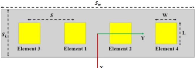
Consider a four-element MPA array along the y-axis as shown in Fig. 1. The dimensions of the proposed antenna have been calculated using transmission line model [10]. The optimized dimensions are listed in Table I. The standard duroid material with εr = 2.2 and 0.254 mm thickness is used as
substrate material. As displayed in Fig. 1, microstrip antennas are placed side by side to form a four-linear array. The center to center element spacing (S) have been maintained as 8 mm, which corresponds to the wavelength of 0.67 λ at 25 GHz. The computed and experimental S-parameters results of the configured linear array (reflection and transmission coefficients) is presented in Fig. 2. The results clearly show that , all four radiators are operating at 25 GHz, while the strongest mutual coupling is recorded between the element 1 & 2(S12), which is close to -23.2 dB.
Table I: Microstrip patch design parameters
Parameter Value (mm) Parameter Value (mm) SL 32 L 3.76 SW 8.6 W 3.76 h 0.254 Q 0.6
Figure 2: S- parameters of the proposed linear array
The array factor of a uniformly placed linear array with an four identical elements that are arranged along the y-axis, is given by [14]: AF = W−2e −j(3 2)Ψ−2+W− 1e−j( 1 2)Ψ−1+W 1ej( 1 2)Ψ1 +W2ej( 3 2)Ψ2 (1) and Ψn= π(n)S λ sin (θ), n=±1,±2. (2) Where Wn is the excitation coefficient (the complex array
element weights), which is the determinant factor of the linear array radiation pattern. The angleθrepresents the direction of the targeted main beam and null direction.
In this work, three beamforming radiation patterns have been defined for different values of θ. The targeted main beam and nulls directions for all three patterns are summarized in Table II. In order to drive the array main lobe at θU
and three nulls at θN1, θN2 and θN3 the complex array
elements weights (Wn0s) are required. The complex weights
are computed through linear algebra method and it is given by [10] : Wn=A−1y (3) where A= ¯a1 ¯a2 ¯a3 a¯4 and ¯ an= h e−j(12)Ψ−1 e−j(32)Ψ−2 ej(12)Ψ1 ej(32)Ψ2 i
Table II: Summary of beamforming patterns.
Pattern Scan angleθU Null 1θN1 Null 1θN2 Null 1θN3
1 0◦ −25◦ +25◦ +50◦
2 +15◦ −35◦ −10◦ +40◦
3 +20◦ −04◦ −35◦ −60◦
Table III: Array elements complex weights
Port 1 Port 2 Port 3 Port 4
Pattern Power (dBm) Phase (deg) Power (dBm) Phase (deg) Power (dBm) Phase (deg) Power (dBm) Phase (deg) 1 −7 0 −7 0 −10 2 −10 −2 2 −7 32 −7 −32 −9 77 −9 −77 3 −8 52 −8 −52 −6 89 −6 −89 y= 1 0 0 0
Wherey is a4×1 forcing function matrix for the steering vector matrix A. Finally, the complex ideal array element weights computed using Equation 3 for the desired scan angles ( as in Table II) has been presented in Table III. It contains the input weights in power and phase form. Furthermore, these weights are calculated under ideal conditions without considering the effects of mutual coupling.
(a) Pattern 1
(b) Pattern 2
(c) Pattern 3
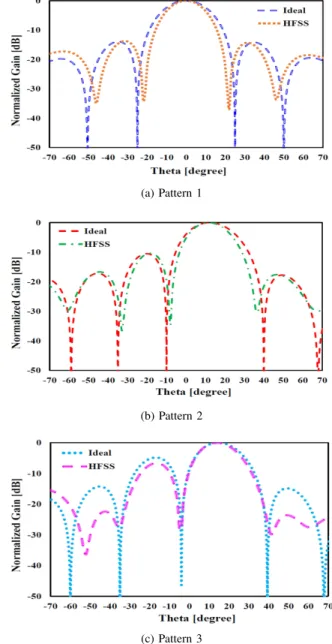
The calculated complex weights have been fed into the HFSS simulation tool. As pointed out previously, the weights are calculated without considering the effects of mutual cou-pling. However, in simulation the mutual coupling effect has been taken into account. Therefore, the simulated array radiation patterns are distorted from the ideal array pattern that is calculated by using Equation 1. For further clarification on the ideal and simulated beamforming patterns of the four-element linear array is presented in Fig. 3.
By examining the results, the main beam positions of the ideal and simulation radiation patterns are almost matched in all three beamforming patterns. However, in simulated beam patterns, the nulls positions and the depth are considerably differed as compared to the ideal array pattern. Furthermore, the beamwidth of the simulated patterns are also slightly reduced. This reduction and shifting in the nulls depth and position is because of the effect of mutual coupling. The solution to this problem is to reduce the mutual coupling between the antenna array elements. In order to reduce the mutual coupling between the array elements, a complementary split ring resonator (CSRR) has been proposed in this work. Therefore in next section the design and analysis procedure of the CSRR element is explained in detail.
III. COMPLEMENTARYSPLITRINGRESONATOR
The mathematical analysis for SRR and its dual counterpart structure CSRR is identical with a suitable interchange of electric and magnetic quantities. In order to achieve the design goal, the dimensions of negative permittivity SRR has initially been calculated and designed. Later, by applying the duality principle the configured SRR structure has been transformed into complementary structure by replacing the conductors part as aperture. The band rejection frequency of the SRR has been numerically calculated using Equation 4. Basically, the total inductance (L) and capacitance (C) of the SRR model are related to the dimensions of the SRR. The relation between the SRR dimensions and resonance frequency has been extensively explained in [41].
f0=
1
2π√LC (4)
In order to numerically characterize the SRR inclusions, the proposed unit cell is designed and positioned at the center of
Figure 4: Unit cell simulation setup
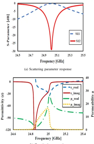
the air-filled waveguide, as shown in Fig. 4. In simulation, the top and bottom sides of a waveguide boundary box are defined as PMC, while its side walls are attributed as PEC walls and the front and back are used for the signal excitation. The computed scattering parameters (S11 and S12) of the
configured SRR, are shown in Fig.5a. The proposed filtering elements exhibit a sharp band rejection at 25 GHz. Moreover, the permittivity (ε) and permeability (µ) of the proposed structure are calculated from the scattering(S)parameters as given by the following Equation 5 [42], [43].
ε=n
z ; µ=n×z (5)
Where refractive index(n)and the wave impedance(z)are calculated using the following equations [42], [43].
n= 1 kdcos −1 " 1−S112 +S212 2S21 # (6) z= s (1 +S11) 2 −S2 21 (1−S11) 2 −S2 21 (7) The calculated constitutive properties are presented in Fig. 5b, the results clearly show the negative responses of perme-ability that can be obtained by configured SRR.
(a) Scattering parameter response
(b) Constitutive properties
Figure 5: Simulated results of SRR unit cell
In order to obtain the negative permittivity filtering struc-ture, the configured SRR structure has been transformed
in to complementary structures using the concept of dual electromagnetic behavior. The configured complementary SRR filtering element is shown in Fig 6. The band stop response of the CSRR structures is slightly varied as compared to the SRR configuration. In order to obtain the stop band response at 25 GHz, the dimensions of the CSRR configuration has been optimized. The computed scattering parameters of the CSRR model for different values of a are displayed in Fig. 7. The parametric results clearly shows that, the stop band response
at 25 GHz is observed at a = 1.43 mm. The optimized
dimensions of the modeled CSRR configuration are listed in the Table IV.
The S-parameter and constitutive properties of the opti-mized CSRR element are given in Fig. 8. The simulation results prove that, the configured complementary structure offer band rejection at 25 GHz and the constitutive results clearly shown that, the complementary structure have negative permittivity response at the required 25 GHz. This negative permittivity CSRR filtering element has capability to decouple the electrically coupled radiating elements. Therefore, in next section the CSRR filtering element is implemented in the four-element beamforming linear array and its performance is studied and compared with conventional antenna array.
Figure 6: CSRR unit cell
Table IV: CSRR unicell dimensions
Parameters Value (mm) Parameters Value (mm)
a 1.43 g 0.15
w 0.15 t 0.035
Figure 7:S12 for different values of ‘a’
(a) Scattering parameter response
(b) Constitutive properties
Figure 8: Simulated results of CSRR unit cell
IV. MUTUALCOUPLINGREDUCTIONINANTENNAARRAY
USINGCSRR
In order to reduce the surface current flow and the mutual coupling between the array radiating elements, an array of CSRR’s have been implemented in between radiating element. The CSRR’s have been arranged in three different orientations such as; parallel orientation (PO), face to face orientation (FFO) and opposite faced orientation (OFO) as shown in Fig. 9 respectively. Initially, the CSRR elements are imple-mented in between the radiators on the top surface of the proposed array, later they have been etched in the ground plan, finally the CSRR elements are implemented in both top and ground surface. The filtering capability of all the nine different configurations has been verified in terms of trans-mission coefficient (S12). The comparison of the simulated
transmission coefficient results of all the nine different con-figurations are presented in Fig. 10. The results clearly show that, as compared to all other configurations the antenna array which contains opposite faced CSRR elements in both top and ground surface have minimum (-44 dB) mutual coupling at the required frequency of 25 GHz. Finally, the Four-element linear antenna array with opposite faced CSRR elements in both top and ground configuration, which is shown in Fig. 11, is chosen as final design. Fig 12 presents the computed scattering parameter responses of the finalized Four-element linear antenna array configuration. As it can be observed from
(a) Parallel (PO) (b) Face to face (FFO) (c) Opposite faced (OFO)
Figure 9: Different orientation of CSRR elements
Figure 10: Mutual coupling(S12)between antenna array with
different CSRR configurations
Fig. 12, the mutual coupling between all the array elements are reduced to -44 dB at the operating frequency of 25 GHz. The obtained additional coupling suppression is nearly 22 dB higher than the simple four-element antenna array (Fig. 2).
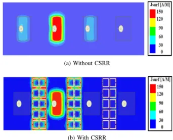
Furthermore, for clarification, the surface current distribu-tion of the four-element antenna array with presence and ab-sence of CSRR elements is analyzed when one port is excited while other ports are terminated with 50 Ω impedance. The
(a) Top surface
(b) Ground
Figure 11: Antenna array with opposite faced CSRR elements
Figure 12: S-parameters of the antenna array with opposite faced CSRR
surface current distribution of the array antenna is presented in Fig. 13. In general the surface current is high in active port and zero at terminated ports. However, by observing the Fig. 13a the surface current is extremely high in active element at the same time small amount of current distribution has been observed in the neighboring elements. In Fig. 13b the surface current flow from the active element to the neighboring elements is controlled by the CSRRs, thus the neighboring elements are completely terminated and almost zero current has been observed.
The aforementioned results confirm that, the presence of the CSRR elements in antenna array control the surface current flow and increase the isolation between array radiators. Hence, the excitation coefficients (which are related to the array radiation) of the array elements are not affected by the mutual coupling.To confirm that, the complex weights given in Table III have been fed in to the CSRRs implemented four-element antenna array. The radiation patterns of the proposed antenna array have been computed and compared with the ideal and simple (without CSRR) antenna array radiation pattern (Fig 14).
Fig. 14 shows the CSRR implemented array antennas simu-lated beam patterns along with the ideal and simple array
an-(a) Without CSRR
(b) With CSRR
(a) Pattern 1
(b) Pattern 2
(c) Pattern 3
Figure 14: Simulated beamforming radiation pattern compar-ison of four-element antenna array.
tenna beam patterns. As compared to the simple array (without CSRR) radiation patterns, the proposed array radiation patterns are very close to the calculated ideal patterns. Specifically, the nulls positions in the CSRR implemented array pattern, when the main beam is at15◦(Fig. 14b), have moved to−34◦, −9◦and39◦, though the nulls depths are increased up to -45 dB. The nulls in the ideal pattern is located at−35◦,−10◦and 40◦respectively, with the null depth of−50dB.Similarly, the beam pattern of the array when the main beam is at 20◦is shown in Fig. 14c. Here, the first null has deepened to about
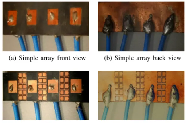
(a) Simple array front view (b) Simple array back view
(c) CSRRs loaded array front view(d) CSRRs loaded array back view
Figure 15: Fabricated four-element antenna arrays
-30 dB and located at the same position of the null in the ideal pattern and other two nulls are located at−36◦and−59◦with -45 dB and -50 dB depth respectively. In ideal pattern, the nulls are located at−4◦,−35◦and−60◦, though the depth are very deep. The results depict that, the nulls depth are significantly increased in proposed antenna arrays, also the nulls positions are fairly conjoined with the calculated nulls positions.
V. EXPERIMENTALRESULTS
To investigate and validate the effects of mutual coupling, a four-element printed antenna array with and without the CSRR elements has been fabricated, as shown in Fig. 15. The array elements are fed by molex flexible cable assemblies. Furthermore, the inner conductor of the cable is adhered to the patch element via a conducting glue and the outer conductor of the cable is soldered to the antenna common ground plane.
A. Measured Scattering Parameter Results
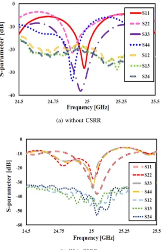
Initially, the scattering parameter measurements for the antenna array have been carried out using keysight PNA-L network analyzer. Before starting the measurement the PNA has been properly calibrated so that the RF cable losses can be properly considered, and their effects are removed from the measurements. Two elements have been measured at a time, while the other two elements have been terminated with matched loads. This has to be done because the PNA has only two ports to measure. The experimental S-parameter results of antenna array with and without CSRR elements are presented in Fig. 16. The experimental results are slightly shifted in both with and without CSRR array antenna case. This shift has been observed due to fabrication inaccuracies and the use of conducting adhesives that has been used to attach the antenna elements and co-axial probe. With the help of CSRR’s the minimum coupling level of -55 dB has been obtained between the element 2 and element 4. Overall, the computed and experimental S-parameters results of both antennas are in close agreement with minor deviations that has been explained previously.
(a) without CSRR
(b) With CSRR
Figure 16: Measured S- parameter results of the antenna array
B. Beamforming Measurements
In this section, the four-element antenna array beamforming measurement procedures and the measured beam patterns of the simple and CSRR loaded antenna arrays are described in detail. The measurement setup is presented first that is followed by the measurement results.
1. Beamforming Experimental Setup
The block diagram of the experimental setup is presented in Fig. 17a. It includes the RF components such as, a low noise amplifier (LNA), 4-way power divider (4WPD), four voltage variable attenuator (VVA) and four voltage variable phase shifter (VVP). As shown in Fig. 17, the LNA feeds the power divider, then four attenuators are attached to the output ports of the power divider. Then four phase shifters are attached to the output ports of each attenuator. Finally the printed antenna array elements are connected to the phase shifters output ports. By varying the biasing voltage, the VVA and VVP provide different values of attenuation and phase shift. The control voltages were fed by the dual port variable DC power source. The real time controller setup is shown in Fig. 17b.
In order to perform the beamforming measurements, it is necessary to know the output attenuation and phase of the real time controller setup. To evaluate the controller setup,
(a) Block diagram
(b) Real time setup
Figure 17: Beamforming measurement setup
port 1 of the PNA-L is connected to the amplifier, whereas port2 is connected to the phase shifter output port, as shown in Fig. 18. The biasing voltages of both voltage variable RF-components are fixed to a value that is close to the computed weight. Finally, the transmission coefficient0S210 provides the actual magnitude and phase of the particular output port. The values of those signals should be nearly equal to the calculated weights which are provided in Table III. This process is repeated for the other ports and other beam scan angles. The particular values of the control voltages for all the attenuators and phase shifters, which give the required attenuation and phase shift for different beam angles, have been noted and later used for antenna array radiation measurements.
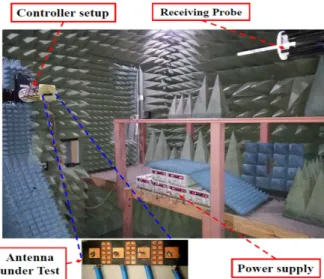
After getting satisfactory results in the above step, the radiation pattern measurements have been carried out in the NSI anechoic chamber. One port of the PNA-L has been connected to the NSI waveguide probe, which was serving as a receiving antenna. The other port of the PNA-L has been connected to 1 ×4 equal power divider via LNA to compensate for the cable losses. A power of 2 dBm has been provided from the PNA-L. The outputs of the 4WPD have been connected to the antenna elements via VVA and VVP
Figure 18: Feed network measurement setup
Figure 19: Measurement setup in anechoic chamber
to achieve the individual weights to be fed to each array element for beamforming applications. Fig. 19 shows the over all beamforming experimental setup in NSI-chamber.
2. Measured Beamforming Pattern Results
The four-element linear antenna arrays, which are displayed in Fig. 15, have been driven with the calculated element weights using VVA and VVP. The beamforming radiation patterns obtained from the experimental setup are shown in Fig. 20. The simple array antenna experimental pattern results are severally affected due to the mutual coupling. However, by observing Fig. 20, it can be easily seen that, the proposed array with CSRR gives better results than the simple antenna array. All three measured pattern results of the proposed array show that, all the nulls positions are almost matched with the calculated ideal array patterns with the nulls depth of up to -40 to -50 dB. Specifically, the measured beam pattern of the array,
(a) Pattern 1
(b) Pattern 2
(c) Pattern 3
Figure 20: Measured beamforming radiation pattern of four-element antenna array.
when the main beam is at15◦and the nulls are at−10◦,−35◦ and+40◦ is shown in Fig. 20b. By observing the results, it can be clearly concluded that the nulls position in the simple array pattern are±2−3◦ deviated from the ideal one. At the same time, the nulls in the CSRR implemented array pattern have the same location as the nulls in the ideal pattern. Moreover, the null located at−10◦is deepened to -30 dB in both simple and proposed array patterns. However, in CSRR implemented array pattern, the other two nulls are deepened about -45 dB, which is nearly 15 dB higher that the simple array patterns nulls depth.
Similarly, the measured beam pattern when the main beam is pointing towards 20◦, is shown in Fig. 20c. In Fig. 20c the ideal pattern nulls are placed at−4◦,−35◦ and−60◦. By comparing the both antenna array patters with ideal pattern, its clear that the simple array pattern has failed to matched with the calculated ideal array pattern. The first null in the simple array is positioned in same location, but the second and third nulls has moved to−32.5◦ and−55◦. In CSRRs implemented array pattern the first two nulls are perfectly placed at −4◦ and−35◦, the third null is slightly shifted from the calculated position and located at −61◦. In addition, all the nulls in the CSRRs implemented array pattern are deeper than the simple array one. The over all results of this work proves that, reducing the mutual coupling between the array elements using CSRR helps to obtain the optimum beamforming performance that is very close to the ideal ones those are considered free of mutual coupling.
VI. CONCLUSION
In this article, a four-element microstrip patch antenna array with complementary split ring resonators for mutual coupling reduction was considered for 5G beamforming application. To investigate the radiation characteristics of the proposed array, three beamforming radiation patterns (main beam at 0◦, 15◦and 20◦) have been considered. The Linear Algebra Method has been utilized to calculate the array elements weights those were then used to steer the main beam in a particular direction and place nulls in other undesired direc-tions. Then the effect of the mutual coupling has been analyzed on all three beamforming patterns. The single negative CSRR has been designed and implemented to reduce the coupling between the array radiators. For the real time verification, the prototype of the antenna array with and without CSRR elements has been developed and the performances were validated in terms of scattering parameters and antenna array beamforming patterns. The voltage variable phase shifters and attenuators has been used for practical implementation of those array element weights. The experimental and computed outcomes showed good agreement. It has been concluded from the experimental results that, the mutual coupling between the array elements has been significantly reduced and the array beamforming patterns has been recovered by implementing the complementary split ring resonators in antenna array. And most importantly, to the best of the authors knowledge, it was observed for the first time that the CSRR worked efficiently in reducing the effect of mutual coupling when the beam was steered off broadside. Previously, CSRR or SRR were implemented in arrays with broadside radiation pattern only and almost no study was carried out on on the effectiveness of CSRRs in a smart beamforming array when the main beam as well as position of nulls was changed to different angles.
ACKNOWLEDGMENT
This work was supported in part by the Ministry of Educa-tion Malaysia, Ministry of Science Technology and InnovaEduca-tion and in part by the Universiti Teknologi Malaysia under Grants 4J211, 03G33, 4S134, and 13H26.
REFERENCES
[1] G. Intelligence, “Global mobile trends 2017,”GSMA, September, 2017. [2] J. G. Andrews, S. Buzzi, W. Choi, S. V. Hanly, A. Lozano, A. C. Soong, and J. C. Zhang, “What will 5g be?”IEEE Journal on selected areas in communications, vol. 32, no. 6, pp. 1065–1082, 2014.
[3] R. I. ITU-R, “R m. 2083-0,”IMT vision–framework and overall objec-tives of the future development of IMT for, 2015.
[4] H. Viswanathan and M. Weldon, “The past, present, and future of mobile communications,”Bell Labs Technical Journal, vol. 19, pp. 8–21, 2014. [5] Z. Pi and F. Khan, “An introduction to millimeter-wave mobile broad-band systems,”IEEE communications magazine, vol. 49, no. 6, 2011. [6] I. GSMA, “Understanding 5g: Perspectives on future technological
advancements in mobile,”White paper, pp. 1–26, 2014.
[7] G. mobile Suppliers Association et al., “The road to 5g: Drivers, applications, requirements and technical development,” 2015. [8] H. T. Friis, “A note on a simple transmission formula,”Proceedings of
the IRE, vol. 34, no. 5, pp. 254–256, 1946.
[9] W. Roh, J.-Y. Seol, J. Park, B. Lee, J. Lee, Y. Kim, J. Cho, K. Cheun, and F. Aryanfar, “Millimeter-wave beamforming as an enabling technology for 5g cellular communications: Theoretical feasibility and prototype results,”IEEE communications magazine, vol. 52, no. 2, pp. 106–113, 2014.
[10] C. A. Ballanis,Antenna theory analysis and design, 4th ed. John Willey and Son’s Inc., New York, 2015.
[11] S. Bellofiore, C. A. Balanis, J. Foutz, and A. S. Spanias, “Smart-antenna systems for mobile communication networks. part 1. overview and antenna design,”IEEE Antennas and Propagation Magazine, vol. 44, no. 3, pp. 145–154, 2002.
[12] S. Bellofiore, J. Foutz, C. A. Balanis, and A. S. Spanias, “Smart-antenna system for mobile communication networks. part 2. beam-forming and network throughput,” IEEE Antennas and Propagation Magazine, vol. 44, no. 4, pp. 106–114, 2002.
[13] M. H. Dahri, M. H. Jamaluddin, M. Khalily, M. I. Abbasi, R. Selvaraju, and M. R. Kamarudin, “Polarization diversity and adaptive beamsteering for 5g reflectarrays: A review,”IEEE Access, vol. 6, pp. 19 451–19 464, 2018.
[14] W. L. Stutzman and G. A. Thiele,Antenna theory and design. John Wiley & Sons, 2012.
[15] R. C. Hansen,Microwave scanning antennas. Academic Press New York, 1964, vol. 1.
[16] H. S. Lui, H. T. Hui, and M. S. Leong, “A note on the mutual-coupling problems in transmitting and receiving antenna arrays,”IEEE Antennas and Propagation Magazine, vol. 51, no. 5, 2009.
[17] I. Gupta and A. Ksienski, “Effect of mutual coupling on the performance of adaptive arrays,”IEEE Transactions on Antennas and Propagation, vol. 31, no. 5, pp. 785–791, 1983.
[18] T. Su and H. Ling, “On modeling mutual coupling in antenna arrays using the coupling matrix,”Microwave and Optical Technology Letters, vol. 28, no. 4, pp. 231–237, 2001.
[19] Z. Huang, C. A. Balanis, and C. R. Birtcher, “Mutual coupling com-pensation in ucas: Simulations and experiment,”IEEE Transactions on Antennas and Propagation, vol. 54, no. 11, pp. 3082–3086, 2006. [20] J. Nasir, M. H. Jamaluddin, M. R. Kamarudin, Y.-C. Lo, R. Selvaraju
et al., “A four-element linear dielectric resonator antenna array for beamforming applications with compensation of mutual coupling,”IEEE Access, vol. 4, pp. 6427–6437, 2016.
[21] Q. Huang, H. Zhou, J. Bao, and X. Shi, “Calibration of mutual coupling effect for adaptive arrays composed of circularly polarized microstrip antennas,”Electromagnetics, vol. 34, no. 5, pp. 392–401, 2014. [22] H. Qiulin, Z. Hongxing, B. Jianhui, and S. Xiaowei, “Mutual coupling
calibration for microstrip antenna arrays via element pattern reconstruc-tion method,”IEEE Antennas and Wireless Propagation Letters, vol. 13, pp. 51–54, 2014.
[23] Y. Yu, H.-S. Lui, C. H. Niow, and H. T. Hui, “Improved doa esti-mations using the receiving mutual impedances for mutual coupling compensation: An experimental study,”IEEE Transactions on wireless communications, vol. 10, no. 7, pp. 2228–2233, 2011.
[24] M. H. Jamaluddin, R. Gillard, R. Sauleau, and M.-A. Milon, “Per-turbation technique to analyze mutual coupling in reflectarrays,”IEEE Antennas and wireless propagation letters, vol. 8, pp. 697–700, 2009. [25] M. S. Wartak, K. L. Tsakmakidis, and O. Hess, “Introduction to
metamaterials,”Phys. Can, vol. 67, pp. 30–34, 2011.
[26] R. S. Kshetrimayum, “A brief intro to metamaterials,”IEEE Potentials, vol. 23, no. 5, pp. 44–46, 2004.
[27] D. Sievenpiper, L. Zhang, R. F. Broas, N. G. Alexopolous, and E. Yablonovitch, “High-impedance electromagnetic surfaces with a forbidden frequency band,”IEEE Transactions on Microwave Theory and techniques, vol. 47, no. 11, pp. 2059–2074, 1999.
[28] D. Ahn, J.-S. Park, C.-S. Kim, J. Kim, Y. Qian, and T. Itoh, “A design of the low-pass filter using the novel microstrip defected ground structure,”
IEEE transactions on microwave theory and techniques, vol. 49, no. 1, pp. 86–93, 2001.
[29] D. Guha, S. Biswas, M. Biswas, J. Y. Siddiqui, and Y. M. Antar, “Concentric ring-shaped defected ground structures for microstrip ap-plications,”IEEE Antennas and Wireless Propagation Letters, vol. 5, no. 1, pp. 402–405, 2006.
[30] C.-Y. Chiu, C.-H. Cheng, R. D. Murch, and C. R. Rowell, “Reduction of mutual coupling between closely-packed antenna elements,”IEEE Transactions on Antennas and Propagation, vol. 55, no. 6, pp. 1732– 1738, 2007.
[31] S. Ghosh, T.-N. Tran, and T. Le-Ngoc, “Dual-layer ebg-based miniatur-ized multi-element antenna for mimo systems,”IEEE Transactions on Antennas and Propagation, vol. 62, no. 8, pp. 3985–3997, 2014. [32] M. M. Bait-Suwailam, M. S. Boybay, and O. M. Ramahi,
“Electro-magnetic coupling reduction in high-profile monopole antennas using single-negative magnetic metamaterials for mimo applications,”IEEE transactions on Antennas and Propagation, vol. 58, no. 9, pp. 2894– 2902, 2010.
[33] S. Gupta, Z. Briqech, A. R. Sebak, and T. A. Denidni, “Mutual-coupling reduction using metasurface corrugations for 28 ghz mimo applications,”
IEEE Antennas and Wireless Propagation Letters, vol. 16, pp. 2763– 2766, 2017.
[34] Z. Qamar, L. Riaz, M. Chongcheawchamnan, S. A. Khan, and M. F. Shafique, “Slot combined complementary split ring resonators for mutual coupling suppression in microstrip phased arrays,” IET Microwaves, Antennas & Propagation, vol. 8, no. 15, pp. 1261–1267, 2014. [35] M. S. Sharawi, M. U. Khan, A. B. Numan, and D. N. Aloi, “A csrr loaded
mimo antenna system for ism band operation,”IEEE Transactions on antennas and propagation, vol. 61, no. 8, pp. 4265–4274, 2013. [36] M. M. Bait-Suwailam, O. F. Siddiqui, and O. M. Ramahi, “Mutual
coupling reduction between microstrip patch antennas using slotted-complementary split-ring resonators,” IEEE Antennas and Wireless Propagation Letters, vol. 9, pp. 876–878, 2010.
[37] R. Selvaraju, M. H. Jamaluddin, M. R. Kamarudin, J. Nasir, and M. H. Dahri, “Complementary split ring resonator for isolation enhancement in 5g communication antenna array,” Progress In Electromagnetics Research, vol. 83, pp. 217–228, 2018.
[38] F. Falcone, T. Lopetegi, J. D. Baena, R. Marqués, F. Martín, and M. Sorolla, “Effective negative-/spl epsiv/stopband microstrip lines based on complementary split ring resonators,”IEEE Microwave and Wireless Components Letters, vol. 14, no. 6, pp. 280–282, 2004. [39] F. Falcone, T. Lopetegi, M. Laso, J. Baena, J. Bonache, M. Beruete,
R. Marqués, F. Martín, and M. Sorolla, “Babinet principle applied to the design of metasurfaces and metamaterials,”Physical review letters, vol. 93, no. 19, p. 197401, 2004.
[40] C. W. Hsue, Y.-W. Chang, and S.-L. Jang, “Comments on babinets prin-ciple,” inForum for Electromagnetic Research Methods and Application Tecchnologies (FERMAT), vol. 16, no. 3, 2016.
[41] J. Naqui, “Symmetry properties in transmission lines loaded with electri-cally small resonators circuit modeling and application to common-mode suppressed differential lines, microwave sensors, and spectral signature barcodes,” Ph.D. dissertation, Universitat Autonoma de Barcelona, Oc-tober 2014.
[42] F. J. Hsieh, C.-L. Chang, and W.-C. Wang, “Determination of effective constitutive parameters, material boundaries and properties of srr-rod and fishnet metamaterials by drude/lorentz dispersion models,” inProgress in Electromagnetics Research Symposium 27-30 March 2012 in Kuala Lumpur, 2012.
[43] D. Smith, D. Vier, T. Koschny, and C. Soukoulis, “Electromagnetic pa-rameter retrieval from inhomogeneous metamaterials,”Physical review E, vol. 71, no. 3, p. 036617, 2005.