25
© Global Society of Scientific Research and Researchers http://asrjetsjournal.org/
Wind Tunnels: State of Art Survey and Future Scope for
Testing Micro Air Vehicles
Royson Donate Dsouza
a*, Samiya Salim
b, Atul Shankar
c, Mohammed Safwan
d,
Sheldon D'sa
ea,b,c,d,eManipal School of Engineering and IT, Dubai, UAE. aEmail: [email protected] bEmail:[email protected] c Email:[email protected] d Email:[email protected] e Email:[email protected] Abstract
Through the years the growth of Micro Aerial Vehicles (MAV) has gained increasing interest among engineers in the applications of military and civil domains. However obtaining accurate aerodynamic flying characteristics of MAV's was considered difficult due to their small size, the nature of their very low Reynolds's number as well as the lack of testing methods. To overcome these complexity, the MAV's can be tested by using a subsonic open circuit micro scaled wind tunnel. This paper presents the development of wind tunnels analyzed from research journals from the year 1937 to 2015 in order fabricate a micro scaled model of the tunnel to test the fundamental aerodynamics of a MAV flying at low speed and low Reynolds's number. The study clearly indicates that micro scaled wind tunnels are certainly bringing infinite possibilities to studying and understanding the in-flight characteristics of very small aircrafts flying at the low speeds and having low aspect ratio.
Keywords: Subsonic Wind Tunnel; Low Cost; Test Section; Aerodynamics; Fluid Flow; Velocity Profile.
--- * Corresponding author.
26
1.IntroductionThe concept of a Micro Aerial Vehicle (MAV) was introduced by the Defense Advanced Research Projects Agency (DARPA) in the mid-1990s as an aircraft measuring less than 6 inches in all dimensions. The design of these vehicles were purely based on the experimental flight testing because of its inaccuracy of available aerodynamic design solvers at low Reynolds numbers and low aspect ratio flight [1]. Complete literature surveys of this area of research can be found in the reference [2,3]. Micro air vehicles are associated with low Reynolds number ranging approximately 200,000 or lower. In addition, due to limitation of size, fixed-wing MAVs are usually designed by very low aspect ratio wing. MAVs that fly using flapping wings hold great potential for indoor investigation and hovering observation.
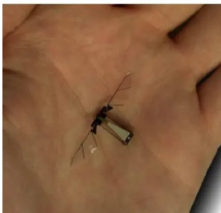
Micro air vehicles have a large array of applications in military and civil domains. It is used as surveillance by defense forces to scout enemy activity, provide combat information and to take aerial photographs of the immediate area with no risk to the soldier's life. It has the potential of a high precision tactical weapon. In addition, the US Air Force Research Laboratory has set a goal to develop a bird sized MAV by 2015 and an insect-sized MAV by 2030 [4]. Apart from that, some of the stimulating research is taking its insight from nature where the development of a number of flapping-wing vehicles have been made that mimics a bird or an insect flight. They are ideal for MAV's as the turbulence in the air affects them much more than larger aircraft. Flapping wing miniature air vehicles (MAVs) offer several advantageous performance benefits, relative to fixed-wing and rotary-wing MAVs. Additional applications of MAV's can be used by law enforcements for traffic control, riot control, hostage rescues. Moreover it has applications in bio chemical sensing, weather forecasting, and inspection of pipes.
Figure 1: Harvard Micro Robotic Fly
The aerodynamics and the wing shape of a MAV plays a crucial role in the design process. It is determined based on the experimental data of a wind tunnel test. However, a preliminary design method must be made by the designer in order to determine the overall size and the shape of the vehicle. A theoretical design procedure is known as follows [5]:
• Determination of the components and take-off weight.
27
• Analyze the required lift co-efficient for a given area to maintain level flight:
2
1
2
V
W
C
S
ρ
=
ι.
(1)Where W is the weight of the aircraft, V is the estimated cruise speed, S is the wing area.
• Apply the wind tunnel data to create predictions of drag co-efficient and lift co-efficient vs. α for different platform profiles.
• Calculation of the angle of attack that is needed to attain the lift co-efficient for changeable wing area and aspect ratio and for different plan form shapes.
• Selection of the wing plan form shape which has the lowest required α and lowest drag co-efficient at
that α.
• Selection of the aspect ratio and wing area which is most suited for mission requirements.
In the past years only a few literature reviews were published associated with the aerodynamics of the micro air vehicle. Mueller and his colleagues [6] designed and constructed a new plan form having force and moment equilibrium to execute lift, drag and moment capacity on MAVs at the low Reynolds numbers. A finite element flow solver based on unstructured grid was designed by Ramamurti and his colleagues [7] to compute the lift and drag force distinction for two MAV models by means of 6-inch and 14.5 inch wingspans correspondingly. Shyy and his colleagues [8] reviewed the scaling laws of biological and micro air vehicles and in turn exposed the kinematics of flapping wings and aerodynamic models for examining lift, drag and power. Waszak [9] and Ifju and his colleagues [10] came with the conclusion that the membrane wing tested in their wind tunnel demonstrated potential benefits to develop the design of the future flight vehicles. Kellogg and his colleagues [11] used CFD (computational fluid dynamics) to investigate the aerodynamic coefficients of a numerous small fixed wing vehicles having its wingspan of 8 ~ 18 inches. Jones and his colleagues [12] investigated the flapping-wing propulsion for small-scale vehicles. The lift and drag of four wing types at the three chords Reynolds numbers of 70,000, 100,000 and 140,000 were deliberated by Torres and his colleagues [13] based on a sensitive force balance in a wind tunnel test.
The following section of the literature will discuss the design of wind tunnels that would facilitate the construction of a smaller scaled tunnel in order to test the application of MAV to evaluate its in-flight distinctiveness. The results based on the wind tunnel test will determine the appropriate MAV to be designed and fabricated with detailed discussions on ground and onboard components such as flight control unit, propeller, vision system, motor, battery and servos etc. Finally, the developed MAV prototype will be successfully tested in the real flight. See reference [14].
2.Wind Tunnels
The field of wind engineering has been developing over centuries since 1871. The definition of a wind tunnel as is given by Pankhurst and Holder (1952), is, “A device for producing a moving airstream for experimental
28
purposes” [15]. Wind tunnel design has evolved with many fluid mechanics as well as engineering theories which are impossible to put out it in this paper. See reference [16]. Since the 1930s, when the strong effect of free stream turbulence on the shear layers became apparent, emphasis has been laid on wind tunnels with low levels of turbulence and unsteadiness [17]. Mehta and Bradshaw conducted a research on the whole design of low speed subsonic wind tunnel.
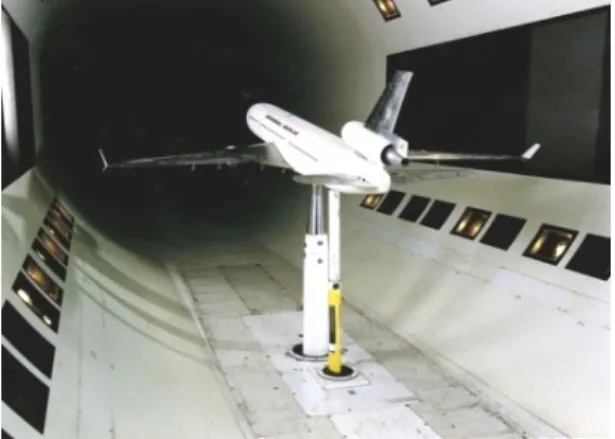
Figure 2: Wind tunnel testing an airplane
Wind tunnels can be classified into four groups which are differentiated by the Mach number or based on flow speed:
i. Hypersonic wind-tunnels (M>5)
The development of new methods of producing hypersonic wind-tunnel flows at increasing velocities during the last few decades is reviewed with attention to air breathing propulsion, hypervelocity aerodynamics and super orbital aerodynamics [18]. These types of wind tunnels find their applications mainly in rocket and space vehicles. They are considered to produce a hypersonic flow having the velocity of the wind between Mach 5 and Mach 15 in the test section. It is the fastest operating wind tunnel in the world. It allows the physical properties of the flow to change rapidly. It operates continuously and air velocities of Mach 10 can be maintained for any length of time. In increasing the Mach number the hypersonic wind tunnel allows aerodynamicists to move on to designing robots, planes and missiles with greater speed. It should be designed or constructed to create the flow features of the given flow system. These flow features include the entropy layer, thin shock layer, viscous interaction and high total temperature of flow [19]. It is also obtained using convergent- divergent nozzles. New studies have found to reduce the noise of hypersonic wind tunnels. They were developed to simulate hypersonic flow in flight, where the noise levels are very low. It requires a laminar boundary layer on the test section walls. [20]
ii. Supersonic wind-tunnels (1<M<3)
A supersonic wind tunnel consists of compressible flow effects when operating at normal conditions [21]. For supersonic wind tunnels, the Mach number is determined by the nozzle geometry and stagnation conditions [22]. This type of wind tunnel has its Mach number between 1 to 3; however the velocity of the air in test section of
29
such wind tunnels can reach up to Mach 5 which is obtained by using convergent - divergent nozzles. While designing the supersonic wind tunnel, it is necessary to determine the generation of supersonic flows in a nozzle. Due to the air flow caused by pressure differential (i.e. the flow of air from high pressure area to low pressure area) the supersonic flow can be driven by producing large enough pressure differential. A supersonic wind tunnel additionally includes compressible flow effects when operating at normal conditions [23].The power requirements for these wind tunnels are also very high. Supersonic wind tunnels are further classified into three type’s i.e. continuous, blow down and in draft tunnels.
iii. Transonic wind-tunnels (M=1)
A transonic wind tunnel was designed, created and regulated in order to offer an important tool to study the phenomena of transonic flow. Transonic wind tunnels with high aspect ratio (2D) are generally operated at higher Reynolds number, it shares the same calibration problems as symmetrical tunnels.[22] Transonic flow occurs when there is mixed sub- and supersonic local flow in the same flow field. Usually the supersonic region of the flow is terminated by a shock wave, allowing the flow to slow down to subsonic speeds. This complicates both computations and wind tunnel testing. It also means that there is very little analytic theory available for guidance in designing for transonic flow conditions [24]. This wind tunnel uses flow properties adjoining the transmission of a shock wave along a tube in order to create the transonic flow. In the transonic wind tunnels, the maximum velocity in test section can reach up to speed of sound i.e. 340m/s or has Mach number equal to 1. These wind tunnels are widespread in the aircraft industry as most aircrafts operate around this speed.
iv. Subsonic or low-speed wind-tunnels (M<1)
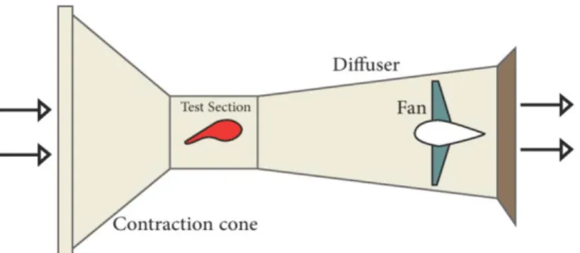
The Mach number is less than 1 and generally comes out to be around 0.4 for this case [25]. The maximum flow speed of a subsonic wind tunnel is measured to be 135m/s. The air density remains constant while decreasing the cross-sectional area allows the flow to increase its velocity and decrease the pressure. Likewise by increasing the cross-sectional area the velocity decreases while the pressure increases. For a subsonic wind tunnel, the test section is placed at the end of the contraction section and upstream of the diffuser. The immediate advantage of this wind tunnel would be to provide the initial operational experience and evaluation of the magnetic balance at a considerably reduced operating cost [26]. They are the most inexpensive compared to the others because of its simplicity in design and the low wind speed. Generally such wind tunnels are found in schools and universities because of its low budget.
30
Table 1: Categorization of flows based on Mach number
Type Gas Velocity Gas or Air Movement Technique Test Duration Model Movement (during test) Test Characteristics References Subsonic Under 600 mph Motor-driven propellers or jet engine exhaust Up to hours in length Can be extensive
Half low-speed data acquisition (100 sps) and half high speed (to 40 KC sps). Variations of tunnel operations. Variations of aerodynamic model altitudes. Essentially steady-state testing IBM 1800 for Wind Tunnel Data Acquisition, pg. 3. Supersonic Mach 1 to Mach 3-5 Pumped chambers or motor-driven A few minutes, depending on velocity, tunnel size and tank storage Usually limited to one or two model changes
High speed data acquisition (5 to 50 KC sps). Some variation of tunnel operations. Few model altitude changes. Hypersonic Mach 3-5 to Mach 8 or more Pumped chambers Up to one or two minutes, depending on velocity, tunnel size and tank storage Usually limited to one or two model changes Same as supersonic Shock wave High pressure change in sealed chamber Very short fractions of a second No model changes
High speed data acquisition only (10-50 KC sps). Start- stop test only
31
Wind tunnel configurations are based on their shape and there are two major types i.e. the open type circuit tunnel and the closed type circuit tunnel. It also includes an intake and exhaust.
The open type wind tunnel has both the ends open. It consists of one or more honeycombs that are used to clean the impurities in the air as there are higher chances of dirt particles entering the system through the air. The power needed to drive the wind tunnel is usually high because of the loss of energy in the outgoing air. The open circuit wind tunnel is the simplest and most affordable to build. In these tunnels air is expelled directly into the laboratory and typically reinvested after circulating through the lab, though some tunnels utilize instead a compressed gas source. The open system however has the problem with excessive noise production limiting the hours that it can be run, however since this wind tunnel is not expected to require utilization late at night this should not be a problem [27]. In addition to their low costs, open circuit tunnels are also advantageous because they have are relatively immune to temperature fluctuations and large disturbances in return flow, provided that the volume of the laboratory is much greater than that of the tunnel [28].
Open type wind tunnels are divided further into two categories which are differentiated by the location of the fan:
i.Suck down tunnel: It consists of a centrifugal blower or an axial fan that is placed after the test section to draw the air in, due to the inlet being open to the atmosphere. This type of wind tunnel is usually not preferred since the air that is entering is of momentous swirl.
Suck down tunnels are typically more susceptible to low frequency unsteadiness in the return flow than blowers, though some claims have been made that intake swirl is less problematic in these tunnels because it does not pass through the fan before entering the test section [29].
ii.Blower tunnel: A blower tunnel consists of a blower that is mounted at the inlet which is used for driving the air flow into the wind tunnel. However, swirling takes place in this tunnel as well but blower tunnels are much less sensitive to it.
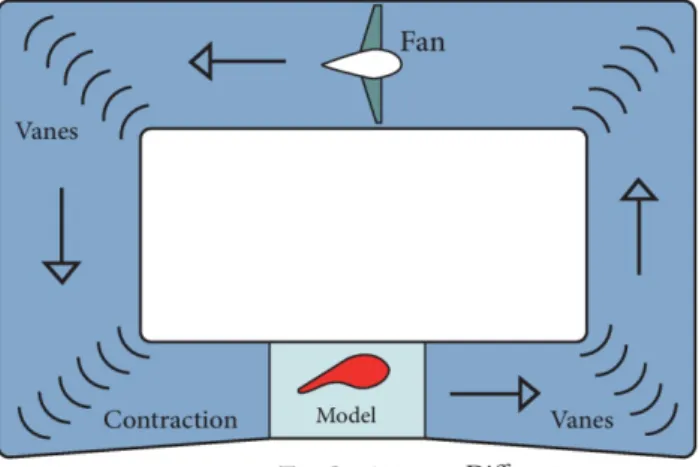
Figure 4: Diagram of an Open Type Wind tunnel
In the closed circuit wind tunnel since the outlet is connected to the inlet, the same air is allowed to circulate throughout the system in a regulated way. It has low chances of dirt entering the system and the power required
32
to obtain a given flow speed is less compared to open circuit tunnels. It forms an enclosed loop in which exhaust flow is directly sent to the tunnel inlet. Closed wind tunnels are proposed warily to make the most of the uniformity of return flow. Based on research by the Tatman, these tunnels are usually large and more difficult to build. These tunnel need to be designed carefully in order to maximize the uniformity of the return flow [30]. The closed system can be fitted with heat exchangers so that it can be used for experiments that are temperature sensitive or require thermal modeling. Because most of the anticipated research would not be temperature sensitive or need thermal modeling it would be suggested to use the open circuit design to save on total costs [31].
Figure 5: Diagram of a Closed Type Wind Tunnel
3. Settling Chamber
The settling chamber is the largest rectangular or a square cross section as well as the most important component of a wind tunnel. The usual arrangement consists of a honeycomb (with about 25000 cells) followed by screens, the number and K-value depending on the turbulence level requirements [32]. It is placed at the entrance of the contraction cone and is used to smooth the flow by eliminating swirl and unsteadiness from the flow. The less turbulent, the better will the wind tunnel simulate flying conditions. When a high quality flow is required, some devices can be installed to increase the flow uniformity and to reduce the turbulence level at the entrance of the contraction. The most commonly used devices are screens and honeycombs. Both devices achieve this goal by producing a relatively high total pressure loss; however, keeping in mind that the local dynamic pressure equals to 1/N2 of the reference dynamic pressure, such pressure loss will only be a small part of the overall one, assuming that N is large enough [33].
i. Honeycomb: The honeycombs are made of hexagonal, circular and square cells as shown in the figure.
These cells can are aligned in the flow direction in the settling chamber and is used to reduce mean or fluctuating variations in transverse velocity with little effect on stream wise velocity because the pressure drop through a honeycomb is small. They are used when flows yaw angles are not greater than about 100. The hexagonal honeycomb is most widely used compared to other shapes as it reduces turbulent flow. See reference [34].
33
ii. Screens: The screens are placed downstream of the honeycomb or sometimes at the inlet section to
reduce turbulent intensity in the flow and to avoid any unwanted objects from entering the tunnel. For large swirl angles, the screen meshes should be placed before the honeycomb. It is characterized by its open area ratio, which is defined as:
2
1
d
L
β
=
−
(2) Where d = wire diameterL= length of the screen.
At least one screen in the settling chamber (ideally the last) should have an open-area ratio of ß<0.57, as screens with lower ratios are known to produced non uniformities in the flow. This is presumable due to the formation of small vortices created by the random coalescence of tiny jets emitted from the screen. [35] The number of screens required depends on the flow quality requirements in the test section. As the number of screens increase, the power requirement increases as well. The effectiveness of screens and honeycomb in reducing turbulence is greatly affected by relatively minor physical damage; therefore, extreme care must be exercised in installing and maintaining honeycomb or screens if the turbulence reduction performance is to be maintained [36].
4. Motor/ Fan Drive Unit
The motor or the supply unit is used to drive the flow of air in the wind tunnel. In general, either an axial or a centrifugal type of fan is used, with the axial fan being the better selection for closed circuit tunnels as it increases the static pressure which is necessary to balance out the total pressure loss in the rest of the circuit. In the case of an open-circuit tunnel, swirl present in the flow out of the fan may be dissipated before the flow reaches the intake, but a remaining advantage of pre rotation vanes is that the flow velocity relative to the fan blades is larger than if the stator is absent or located downstream of the fan [37]. The fans having a high ratio of tip speed to the axial velocity typically produces the necessary pressure rise in the small blade area. The centrifugal impeller of the squirrel-cage type drives the wind tunnels that are fitted with a blower. The fan is used to draw the air in from the atmosphere through the honeycomb mesh or screen section. A control box with a pull chain control drives the fan motor between the off position and a low and high speed setting. This limited the range of possible experimental velocities [38].
5. Contraction Cone
The most important purpose of the contraction section is to accelerate the incoming flow from the settling chamber and supply it to the test section at preferred velocity. In designing the contraction cone for a wind tunnel, the usual design condition is that the velocity at the end of the cone must be fairly uniform [39]. This
34
section basically diminishes the cross-sectional velocity deviation and upholds the uniformity of flow. The size and shape of the contraction dictate the final turbulence intensity levels in the test section [40]. In general, a small radius of curvature is used at the entrance of the section and a large radius of curvature is measured at the exit of the contraction section. On the other hand, the boundary-layer division should be avoided at both the ends of this section. The contraction length is likely to be small so that large contraction area ratios are favored. Most analytical methods of contraction design have been based on Stokes' Stream Function for the steady axisymmetric flow of an incompressible in viscid fluid i.e. [41].Most analytical solutions were found by the method of separating variables in equation 1.
1
U
r
r
∂Ψ
=
∂
(3)1
V
r
x
∂Ψ
= −
∂
(4)Where x, y are coordinates in the axial and radial direction and U, V are respective fluid velocities i.e. given by:
2 2 2 2
1
0
x
r
x
r
∂ Ψ
−
∂Ψ ∂ Ψ
+
=
∂
∂
∂
(5) 6. Test SectionThe test section is the basic element of wind tunnel on which the designs on different vehicles are usually made. All the aerodynamic models are mounted in the test section when the tunnel is activated with desired flow velocity. Aerodynamic performance of the models can be better matched to full-scale performance in a closed test section; however, an open jet permits far-field acoustic measurements at the cost of potential test section jet deflection, jet/collector interactions, and shear layer refraction [42]. The test section can be of various shapes for constructing the wind tunnel i.e. hexagonal, octagonal, rectangle etc. The ratio of width to height of a test section is generally chosen with the intended purpose of the wind tunnel in mind. For example, a wind tunnel intended for testing wing sections will usually be wider than it is tall (often in a ratio of 3:2), whereas a wind tunnel designed for testing of architectural models will normally be taller than it is wide [43]. It is generally designed on the foundation of effectiveness and aerodynamic considerations since cost of construction depends on the test section area. Length of the test section is typically equivalent to main dimension of the cross-section of the similar or twice of it. Moreover, the test section should also be supplied with facilities as per the testing necessity. A common rule of thumb in test section sizing is to have rectangular dimensions with a ratio of about 1.4–1 [44]. The test section velocity is commonly determined as percentage variation from the average of the cross-section. The ideal test section has steady uniform velocity at the inlet having no cross flow with less or no turbulence and low operating cost.
35
7. DiffuserBarlow, Rae and Popestates that for a conical diffuser, the divergence half angle of the diffuser walls should be
less than 3.5◦ for a “good” design [45]. Mehta states that the diffuser-included angle for a conical diffuser
should be between 5◦ (for best flow steadiness) and 10◦ (for best pressure recovery) [46]. It is usually a duct with larger area that is installed downstream of the test section. This allows the air to pass smoothly out of the test section and to decrease the flow velocity while increasing the pressure. In the case of an open wind tunnel, the exit pressure of the air should be greater than the atmospheric pressure in order to avoid reverse of flow. This is a very crucial division in design as the acquired pressure rise diminishes the power constraint for the wind tunnel which is directly proportional to the cube of velocity. Therefore the foremost objective of diffuser design is to achieve the maximum pressure recovery at the least possible distance. To avoid the boundary layer separation, the cone angle of the diffuse is made 7º or lesser. There are two main types of the diffuser:
i.Exit Diffuser: These diffusers are installed at the downstream of the working section and consist of a diffuser with gentle expansion having an angle not more than 5 degree. The design of these diffusers is well catered for by existing methods [47].
ii.Wide- angle Diffuser: This type of diffuser is normally placed between the blower and the settling chamber or between the fourth corner and settling chamber of a closed-circuit tunnel [48]. It is used for decreasing the length for a given area ratio rather than having an effect on the pressure recovery. Usually the total pressure rise in a wide angle diffuser is negative but small.
8. Turning Vanes
Turning vanes are generally chambered aerofoil of bent planes that are provided at the corners of the wind tunnel having two bends aligned 900 to each other in a closed circuit wind tunnel. It is used to allow the air to circulate smoothly in a controlled manner. These vanes are deliberately made as adaptable for even operation thus avoiding under/over tuning. The vanes were tested with a flap in a recent study where on one hand, the presence of flaps increases the pressure loss due to the increase of the friction surface, whereas on the other hand the flaps improve the quality of the upstream flow into diffuser 1 and might also affect the test chamber if the damped pressure perturbation is intense enough. The presence of flaps reduces the pressure loss by diminishing the turbulence level in the corner [49].
9. Optical Components
For an open-jet test section, a collector is required at the downstream end of the test section to capture the jet. The resulting flow pattern is highly dependent on the room characteristics and the test configuration/conditions [50]. By using Computational Fluid Dynamics the design of the area of the collector can be best determined. However it has disadvantages like the noise produced due to the boundary-layer scrubbing and the turbulent shear layer impingement on the collector.
For closed-circuit tunnels where the ducts are fixed together by 90 degree bends, there will be flow separation that would lead to significant pressure drop, flow unsteadiness, and noise generation. Collar and Salter
36
developed some early designs for turning vanes [51]. Gelder and his colleagues. developed turning vanes with a low loss factor [52]. Mechanical vibrations generated by the drive system can propagate into the test section through ductwork and the ground. These vibrations must be minimized if aero-optic, transition, or acoustic measurements will be conducted. Vibration isolation devices consist of passive and active mounts, as well as a flexible bellows section [53].
10. Facility Characterization
In order to determine if the design criteria of a wind tunnel is satisfied, it must be characterized. The most obvious test is to check that the facility operates safely at desired flow speeds, but beyond this a series of careful experiments are recommended [54]. Some of the types of characterization experiments are given below:
i. Flow uniformity: There are a large number of experimental techniques available to measure the mean
velocity profile [55] including transversing a pitot-static or pitot probe through the test section. It is proven and cost effective but a time consuming experiment. The flow uniformity is usually characterized as either as a min–max or an rms deviation from the mean velocity in the inviscid core flow of the test section [56].
ii. Turbulence characterization: The low turbulence in the test section for a numerous facilities are critical. Wind tunnels often isolates the effects of incoming free stream of turbulence. In aero acoustic studies, ingested turbulence can interact with model components and generate additional “leading edge” noise, contaminating measurements of other components of interest, such as airfoil trailing edge noise [57]. iii. Acoustics and vibration : The background noise of a facility must be assessed if the facility is used for
acoustic measurements. It should have a background noise levels at least 10 dB below the acoustic source of interest in a test, constraints and requirements. [58].
11. Flow Visualizations
Flow visualizations are qualitative examination of flow that are important in understanding the aerodynamic characteristics of MAV models in wind tunnels. Two different methods can be used to generate smoke for flow visualization. With the first method, smoke is generated by a device which allows kerosene to drip onto electrically heated filaments; the smoke is then funneled to a smoke rake. The rake has a filter bag and cooling coils which reduce the smoke temperature to approximately ambient before passing through the anti-turbulence screens and into the test section. With the second method, a fine wire is placed upstream of the model. This wire is coated with oil and an electric current is applied to the wire. As the wire gets heated, the small beads of oil formed on the wire burn, which gives rise to fine smoke streak lines. This technique, which has been described in more details in the reference [59]. This is referred to as the smoke-wire technique.
Fluid that creates colored fog has been tried but never satisfactorily worked without seriously damaging the smoke machine and is not available anywhere. In order to get the colored smoke for flow visualization, we'll be using normal smoke fluid (white smoke) and wash the smoke with colored lighting. The white fog particles will defract the light and will make it look like colored smoke. Another alternative is to use theatrical colored
37
smoke pyrotechnics that actually make proper, real colored smoke - but they have the potential to stain fabrics and materials. The smoke when comes into contact can be hazardous and should be avoided breathing the smoke.
12. Review Discussion
While the technology development in the field of MAVs are drastically increasing, the demand for such wind tunnels are also enhanced at the same time. There are many domains of interest in MAVs in which the prospected effort can offer further approach to designers. For example:
• Improvement of different mechanism models by using miniaturized strain gages, and a variety of
dynamic characterization tests
• 3-D motion tracking of wing deformation by filming the motions of the wing or using multiple camera
angles.
• Improvements in the load cell measurement techniques that measures the lift and thrust forces for each
set of wings.
• Unvarying Construction of Wing Techniques.
As for the future works of a wind tunnel, these micro scaled apparatuses can be available for a broad range of testing and can be presented for educational and research purposes that can be accessed for future experiments. The construction of this tunnel is inexpensive and easy to use. It has the possibility to support the perceptive of aerodynamics implicated in upcoming student projects as well.
13. Conclusion
A survey of literature on the history of low cost wind tunnels and the local sections of the wind tunnel were discussed thoroughly in this paper. It is customary to construct a model prototype wind tunnel before the full-scale wind tunnel to work out design problems early in the design cycle. The low cost wind tunnel testing will focus on flow stability and uniformity in the test section as well as the maximum attainable wind speed of various micro air vehicles.
By constructing a wind tunnel the main goal is to carry out experiments on different types of airfoils in the laboratory. The current research can be extended to include other parameters like flow visualization over test specimens of different materials through smoke, installing six force sensors for measurement of yaw, pitch and roll & automation of tunnel for data acquisition. The idea of the design and development of a subsonic micro scaled wind tunnel that would generate on low speed will have high potential in studying the aerodynamic characteristics of these minute air vehicles like the flapping wing. These micro scaled wind tunnels are strongly recommended for the validation of concept and the design of micro air vehicles. Furthermore, the experimental analysis of a flapping wing MAV, will further determine if the prototype will be developed or not. Upcoming research with wind tunnels should embrace the expansion of a more sensitive measurement apparatus.
38
AcknowledgementsWe would like to acknowledge the authors and our assistant professor for their relevant contribution to the accomplishment of this study.
References
[1] Mueller, T.J., “Aerodynamic Measurements at Low Reynolds Numbers for Fixed Wing Micro Aerial
Vehicles”, presented at the "Development and Operation of UAVs for Military and Civil Applications" course held at the von Karman Institute for Fluid Dynamics, Belgium, September 13-17, 1999.
[2] Mueller, T. J., "Low Reynolds Number Vehicles", AGARDograph No. 288, 1985
[3] Lissaman, P. B. S., "Low-Reynolds-Number Airfoils", Annual Review of Fluid Mechanics, Vol. 15, 1983, pp. 223-239
[4] Kai Liu, Andrea Da Rounch, Daochun Li, Jinwu Xiang, "Modeling of Unsteady Aerodynamics for a
Flapping Wing", School of Aeronautic Science and Engineering, Beihing Univ, Beijing, 2015.
[5] Gabriel Torres and Thomas J. Mueller, "Micro Aerial Vehicle Development: Design, Components,
Fabrication and Flight Testing", Univ of Notre Dame, 46556.
[6] T. J. Muller, “Aerodynamic measurements at low Reynolds numbers for fixed wing micro-air
vehicles,” Development and Operation of UAVs for Military and Civil Applications, pp. 8-1-8-32, April 2000.
[7] R. Ramamurti and W. Sandberg, “Simulation of the dynamics of micro air vehicles,” AIAA
2000-0896, 10-13 January 2000.
[8] W. Shyy, M. Berg, and D. Ljungqvist, “Flapping and flexible wings for biological and micro
Vehicles,” Process in Aerospace Sciences, vol.35, no.5, 1999, pp. 455-506.
[9] M. R. Waszak, L. N. Jenkins and P. G. Ifju, “Stability and control properties of an aeroelastic fixed wing micro aerial vehicle,” AIAA 2001-4005
[10] P. G. Ifju, D. A. Jenkins, S. Ettinger, Y. Lian, W. Shyy, and M. R. Waszak, “Flexible-wing-based
micro air vehicles,” AIAA 2002-0705.
[11] Kellogg, C. Bovais, and R. Foch R, and his colleagues . “The NRL micro tactical expendable (MITE)
air vehicle,” Aeronautical Journal, August 2002, vol.106, pp. 431-441.
[12] D. Jones and M. F. Platzer, “An experimental and numerical investigation of flapping-wing
propulsion,” AIAA-99-0995.
[13] G. Torres and T. J. Mueller. “Micro aerial vehicle development: design, components, fabrication, and flight-testing,” Presented at the AUVSI Unmanned Systems 2000 Symposium and Exhibition, Orlando, FL, July 11-13, 2000.
[14] Dong Sun, Huaiyu Wu, Rong Zhu, Ling Che Hung, " Development of Micro Air Vehicle Based on
Aerodynamic Modeling Analysis in Tunnel Test", International Conf. on Robotic and Automation, IEEE, Barcelona, Spain, April, 2005
[15] Craig A. Zehrug: “Comparative Analysis of a Low-Speed Wind Tunnel Designed for Renewable
Energy Applications”. Purdue University Purdue e-Pubs College of Technology Theses and Projects, Page-10, 2011.
39
[16] Rae, W. H. Jr. and Pope A., Low-Speed Wind Tunnel Testing, John Wiley & Sons, 2nd Ed., 1984. [17] R.D. Mehta and P. Bradshaw, "Design rules for small low speed wind tunnels", The Aeronautical
Journal of the Royal Aeronautical Society, Nov., 1979.
[18] R.J. Stalker, "Modern developments in hypersonic wind tunnels", Centre for Hypersonic, Univ. of Queensland, Brisbane, Australia.
[19] Experimental Hypersonic Test Facilities and Measurements, NPTEL, aerospace, [Online]. Available:
http://nptel.ac.in/courses/101103003/pdf/mod7.pdf
[20] Hadassah Naiman,"Analysis and Design of Quiet hypersonic wind tunnels", Dissertation, Ph.D,
Rutgers, The State University of New Jersey, Jan. 2010.
[21] William Bugden, Katherine Fitton, Geordia Folinas, Nathan Fournier, Gallagher Hogan, Markus Ito,
Joshua Lambert, Neel Patel, Dong-Uk Shin, Grant Wont, Earl Ziegler, "Design and Construction of a Supersonic Wind Tunnel with Diagnostics," Worcester Polytechnic Institute, JB3-SWT3, April 17,2013
[22] T.D. Reed, T.C. Pope, and J. M. Cooksey, "Calibration of Transonic and Supersonic Wind Tunnels", Nasa Contractor Report, NAS2-8606, Nov., 1977
[23] Moore P. Design of a Supersonic Wind Tunnel. Major Qualifying Project. Worcester Polytechnic
Institute 2009. ME-JB3-SWT1.
[24] W.H. Mason, "Transonic Aerodynamics of airfoils and wings", Mar. 2006
[25] NORLIZAA BT MOHAMAD, "Design and development of wind tunnel for contraction ratio effects
to the velocity and boundary layer thickness, B.Me Thesis, Dept., Manufacturing Engg., Univ. Malaysia Pahang, June 2012.
[26] Milan Vlajinac, "Design, Construction and Evaluation of a Subsonic Wind Tunnel, Thesis, M.sc.,
Massachusetts Institute of Technology, June, 1970
[27] Barlow, Jewel B., William H. Rae, and Alan Pope. Low-speed wind tunnel testing. 3rd ed. New York:
Wiley-Interscience, 1999.
[28] Mansi Singh, Neha Singh & Sunil Kumar Yadav “Review of Design and Construction of an Open
Circuit Low Speed Wind Tunnel” Volume 13 Issue 5 Version 1.0 Year 2013Online ISSN: 2249-4596 Print ISSN: 0975-5861 Publisher: Global Journals Inc. (USA)
[29] Mansi Singh, Neha Singh & Sunil Kumar Yadav “Review of Design and Construction of an Open
Circuit Low Speed Wind Tunnel” Volume 13 Issue 5 Version 1.0 Year 2013Online ISSN: 2249-4596 Print ISSN: 0975-5861 Publisher: Global Journals Inc. (USA)
[30] Nathan Tatman, “Wind Tunnel Design and Operation”, a thesis paper submitted for undergraduate
degree, 2008
[31] Barlow, Jewel B., William H. Rae, and Alan Pope. Low-speed wind tunnel testing. 3rd ed. New York:
Wiley-Interscience, 1999.
[32] Mehta, R.D. and Bradshaw, P., “Design Rules for Small Low Speed Wind Tunnels,” Aetonaut. J..
vol.83. 30.827. November 1979, pp. 447-458.
[33] Miguel A. González Hernández, Ana I. Moreno López, Artur A. Jarzabek, José M. Perales Perales,
Yuliang Wu and Sun Xiaoxiao," Design Methodology for a Quick and Low-Cost Wind Tunnel", Polytechnic University of Madrid, Spain and Beijing Institute of Technology, China.
40
[34] EFFECT OF SQUARE CELLS IN IMPROVING WIND TUNNEL FLOW QUALITY, presented at
the Conf., The Seventh Asia-Pacific Conference on Wind Engineering, Tapei, Taiwan, Nov. 8-12, 2009.
[35] Norlizaa BT Mohamad, "Design and development of wind tunnel for contraction ratio effects to the velocity and boundary layer thickness, B.Me Thesis, Dept., Manufacturing Engg., Univ. Malaysia Pahang, June 2012.
[36] James Scheiman, "Considerations for the Installation of Honeycomb and Screens To Reduce
Wind-Tunnel Turbulence", NASA-TM-81868 19810020599
[37] Mehta, R.D. and Bradshaw, P., “Design Rules for Small Low Speed Wind Tunnels,” Aetonaut. J..
vol.83. 30.827. November 19T9, pp. 447-458.
[38] Kashif Javed, Mazhar Ali, "Design & Construction of subsonic wind tunnel focus on two dimensional contraction cone profile using sixth order polynomial"
[39] Hsue-Shen Tsien. "On the Design of the Contraction Cone for a Wind Tunnel", Journal of the Aeronautical Sciences, Vol. 10, No. 2 (1943), pp. 68-70.
[40] Derbunivich, G.I., Zemskaya, A.S., Repik, E.U. and Sosedko, Y.P. (1987) Effect of flow contraction
on the level of turbulence. Izv. Akad. Nauk SSSR Mekh. Zhidk. Gaza, 2, 146–152
[41] Jonathan H. Watmuff, "Wind Tunnel Contraction Design", presented at the Conf., Fluid Mechanics Conference, Auckland, Dec., 8-12, 1986
[42] Amiet, R.K. (1978) Refraction of sound by a shear layer. J. Sound Vib., 58(4), 467–482
[43] Andrew R. Coggan, "The Coggan Low Speed Wind Tunnel: Design, Dimension and Operating
Characteristics, Thesis, Ph.D, Nov, 2011.
[44] Bradshaw, P. and Mehta, R. (2003) Wind Tunnel Design,
http://www-htgl.stanford.edu/bradshaw/tunnel/ (accessed 18 June 2009
[45] Barlow, J.B., Rae, W.H. Jr. and Pope, A. (1999) Low-Speed Wind Tunnel Testing, 3rd edn, John
Wiley and Sons, New York.
[46] Mehta, R.D. (1977) The aerodynamic design of blower tunnels with wide angle diffusers. Progr.
Aerosp. Sci., 18, 59–120.
[47] Cockrell, D.J. and Markland, E. Diffuser behaviour- a review of past experimental work- relevant
today. Aircr Engng, Vol 46, p 16 (reprint of Vol 35, p 286), 1974
[48] Mehta, R.D. and Bradshaw, P., “Design Rules for Small Low Speed Wind Tunnels,” Aetonaut. J..
vol.83. 30.827. November 19T9, pp. 445-446
[49] Luis Lopez de Vega, Francisco Javier Maldonado Fernandez, Pedro Munoz Botas, " Optimisation of a Low Speed Wind Tunnel; Analysis and Redesign of Corner Vanes" , May 2014.
[50] Louis Cattafesta, Christopher J. Bahr, Jose Mathew, " Fundamentals of Wind Tunnel Design", Dept., of Mech. and Aero. Engg., Univ. of Florida, Gainesville, FL, USA, Feb 7, 2016
[51] Collar, A.R. (1937) Some experiments with cascades of aerofoils. A.R.C., Reports and Memoranda
Technical Report 1768.
[52] Salter, C. (1946) Experiments on thin turning vanes. A.R.C., Reports and Memoranda, no. 2469.
[53] Beranek, L.L. and Ver, I.L. (1992) Noise and Vibration Control Engineering - Principles and
41
[54] Louis Cattafesta, Christopher J. Bahr, Jose Mathew, " Fundamentals of Wind Tunnel Design", Dept., of Mech. and Aero. Engg., Univ. of Florida, Gainesville, FL, USA, Feb 7, 2016
[55] Tavoularis, S. (2005) Measurements in Fluid Mechanics, Cambridge University Press, New York.
[56] Mathew, J. (2005) Design, fabrication and characterization of an anechoic wind tunnel facility. PhD. MAE Department, University of Florida.
[57] Brooks, T.F., Pope, D.S. and Marcolini, M.A. (1989) Airfoil self noise and prediction. NASA
Reference Publication 1218, July 1989.
[58] Duell, E., Yen, J., Walter, J. and Arenette, S. (2004) Boundary layer noise in aeroacoustic wind
tunnels. 42nd AIAA Aerospace Sciences Conference. AIAA Paper 2004-1028. Reno, Nevada, January 2004.
[59] Thomas J. Mueller, "Aerodynamic Measurements at Low Reynolds Numbers for Fixed Wing
Micro-Air Vehicles", Conf., Development and Operation of UAVs for Military and Civil Applications, Sept., 1999.