3 Special
Craft
2 Yachts
≥
24 m
The following Rules come into force on October 1
st, 2003
Germanischer Lloyd Aktiengesellschaft
Head Office
Vorsetzen 35, 20459 Hamburg, Germany
Phone: +49 40 36149-0
Fax: +49 40 36149-200
[email protected]
www.gl-group.com
"General Terms and Conditions" of the respective latest edition will be applicable
(see Rules for Classification and Construction, I - Ship Technology, Part 0 - Classification and Surveys).
Reproduction by printing or photostatic means is only permissible with the consent of
Germanischer Lloyd Aktiengesellschaft.
Published by: Germanischer Lloyd Aktiengesellschaft, Hamburg
Printed by: Gebrüder Braasch GmbH, Hamburg
Table of Contents
Section 1 General Requirements
A. Application, Scope ... 1- 1 B. Hull Structures ... 1- 5 C. Machinery Installations ... 1- 6 D. Electrical Installations ... 1- 8 E. Documents for Approval ... 1- 9
Section 2 Hull Structures
A. General, Definitions ... 2- 1 B. Materials, Corrosion Protection and Joining Technology ... 2- 5 C. Design Principles ... 2- 18 D. Motor und Sailing Yachts, 24 m ≤ L ≤ 48 m Steel and Aluminium Structures ... 2- 33 E. Motor and Sailing Yachts, 24 m ≤ L ≤ 48 m, Composite Structures ... 2- 47 F. Motor und Sailing Yachts, 24 m ≤ L ≤ 48 m, Wooden Structures ... 2- 57 G. Motor and Sailing Yachts, L > 48 m, Steel and Aluminium Structures ... 2- 57 H. Tank Structures ... 2- 58 I. Chainplates, Ballast Keel, Propeller Brackets ... 2- 61 J. Rudder and Manoeuvring Arrangement ... 2- 63 K. Anchor and Mooring Equipment ... 2- 77 L. Masts and Rigging ... 2- 81
Section 3 Safety Requirements
A. Safety Appliances and Provisions ... 3- 1 B. Structural Fire Protection ... 3- 1 C. Fire Protection and Fire Extinguishing ... 3- 11 D. Closure Conditions, Buoyancy and Stability ... 3- 14 E. Requirements for Hydraulically-Operated Equipment ... 3- 24 F. Requirements for Helicopter Facilities ... 3- 28 G. Systems for Breathing Gases and Diving ... 3- 34
Section 1
General Requirements
A. Application, Scope1. Application
1.1 These Rules apply to large, seagoing motor and sailing yachts with a length L≥ 24,0 m for pri-vate, recreational use, provided that the yacht classed and approved in accordance therewith is at all times employed exclusively under the conditions for which it has been designed, constructed and approved and that it is equipped and handled in the sense of good seamanship, and operated at a speed adopted to the respective seaway conditions.
Designs which deviate from these Rules may be ap-proved, provided that such designs have been exam-ined by GL for suitability and have been recognized as equivalent.
Notes containing amendments, recommendations, etc. are always printed in italics. Other italic script in these Rules indicate matters not part of Classification.
Note
Ships with 24 m ≤L≤ 48 m intended for commercial purposes which do not carry more than 12 passen-gers, may be dimensioned according to Section 2, D. and E. of these Rules, taking supplementary factors into account, which have to be agreed upon with GL. The length L is defined in Section 2, A.6.
1.2 Whether and/or to which extent the GL Rules Part 1 – Seagoing Ships, Chapter 5 - High Speed Craft may have to be applied to a particular design will be decided in the individual case.
1.3 Yachts with a length 6 m ≤ LSC≤ 24 m are
covered by the GL Rules Part 3 – Special Craft, Chap-ter 3 – Yachts and Boats up to 24 m and are not sub-ject of these Rules.
2. Special aspects for yachts
Contrary to merchant ships the following aspects will usually apply regarding the operation of yachts: – less severe operating conditions as for ships in
regular trade
– limited yearly sea hours in relation to harbour hours
– special care by the owner and usually good maintenance
These Rules were developed assuming these charac-teristics.
3. Scope
3.1 The requirements of these Rules do not sub-stitute the independent judgement of professional designers. This is particularly valid for those aspects not addressed in these Rules and for which the design-ers are solely responsible.
3.2 The Rules envisage primarily technical safety matters. Aesthetical and comfort aspects, usually im-portant in yacht design, are not considered and must be subordinated to the safety requirements in conflict cases.
4. Scope of Examination/Classification ac-cording to GL Rules
4.1 Plan approval
Plan approval will only be carried out once appropri-ate and sufficient documentation has been submitted to GL.
4.2 Hull Construction Certificate
The scope of examination and construction survey related to the issuance of a Hull Construction Certifi-cate refers to the hull structure only. The hull structure has to be in compliance with the relevant scantling requirements of these Rules.
4.3 Classification
If a yacht is subject to Classification, all aspects in addition to the hull structure, i.e. machinery and elec-trical installations and ship safety matters have to be considered and must comply with the requirements of these Rules. The GL Surveyors will supervise the complete construction phase of the yacht. As Class is granted only for a limited period of time, the complete surveying procedures during service of the yacht have to be established if Class of the yacht shall be main-tained.
For more details about Classification and Class Nota-tions see GL Rules Part 0 – Classification and Sur-veys, Section 2.
5. Types of yachts
In addition to the Character of Classification, yachts will be characterized by Notations affixed, describing their type and envisaged use, as shown in the follow-ing examples.
SAILING YACHT
MOTOR YACHT
SPECIAL YACHT
Note
The term "special" applies to yachts of unusual shape/dimensions and with special technical equip-ment, if any. GL reserve the right of determining whether the GL Rules are applicable and how they are to be interpreted.
6. Consideration of other regulations 6.1 National regulations of various flag states GL is prepared to include in its supervisory proce-dures the national regulations of the flag state of the yacht if the owner of the yacht wants to include this additional service and if GL is authorized by the par-ticular flag state to do so.
6.2 Regulations of the Maritime and Coast-guard Agency (MCA)
GL is prepared to consider in addition to its own Rules the regulations of the UK Maritime and Coastguard Agency if the owner of a yacht chooses this option. 7. Range of service
Yachts complying with the Construction Rule re-quirements for a restricted range of service only will have the Notations specified below affixed to their Character of Classification.
M (Restricted International Service)
This range of service is limited, in general, to voyages along the coast, provided that the distance to the near-est port of refuge and the offshore distance do not exceed 200 nautical miles. This applies also to voy-ages in the North Sea and within enclosed seas, such as the Mediterranean, the Black Sea and waters with similar conditions. Voyages to Iceland, Spitzbergen and the Azores are exempted.
K (Coastal Service)
This range of service is limited, in general, to voyages along the coasts, provided that the distance to the nearest port of refuge and the offshore distance do not exceed 50 nautical miles. This applies also to voyages within enclosed seas such as the Baltic Sea and gulfs with similar seaway conditions.
Where a permissible distance of less than 50 nautical miles has been fixed for a yacht, the relevant distance will be added in brackets behind the Notation K in the Class Certificate, e.g. K(20).
W (Sheltered Water Service)
This range of service is limited to voyages in shoals, bays, haffs and firths or similar waters, where heavy seas do not occur.
The Notations may possibly be assigned on the basis of the seaway conditions prevailing in the respective service area (e.g. official seaway statistics).
Observance of the range of service boundaries is a prerequisite for validity of the Class.
GL may, on application, agree to the range of service being extended for a limited period and/or with certain reservations. This will have to be documented. 8. Ambient conditions
8.1 General operating conditions
The selection, layout and arrangement of the yacht's structure and all shipboard machinery, equipment and appliances shall be such as to ensure unobstructed continuous operation under the ambient conditions specified in these Rules.
8.2 Inclinations and movements of the yacht The design limits for yacht inclinations and move-ments are defined in Table 1.1.
Account is to be taken of the effects of distortion of the yacht's hull on the machinery installations.
8.3 Environment of the yacht
The design environmental conditions of a yacht are defined in Table 1.2.
9. Vibrations and noise
Vibrations are defined as structural oscillations in the frequency range of 1 Hz to 80 Hz. Noise is defined as audible air pressure variations, generated for instance by main engines and propellers, auxiliary machinery, equipment and persons within the frequency range of 16 Hz to 16 000 Hz.
Table 1.1 Design limits for yacht inclinations and movements
Type of movement Type of inclination Standard requirements Inclination athwartships: 1
Main and auxiliary machinery 15° 2
Other installations 3 22,5° 2
No uncontrolled switches or
functional changes 45° 2
Yacht's structure acc. to stability requirements
Inclination fore and aft: 1
Main and auxiliary machinery 15°
Other installations 3 10°
Static condition
Yacht's structure acc. to stability requirements
Rolling:
Main and auxiliary machinery 22,5°
Other installations 3 22,5°
Pitching:
Main and auxiliary machinery 7,5°
Dynamic condition
Other installations 3 7,5°
1 athwartships and fore and aft inclinations may occur simultaneously 2 for sailing yachts special considerations may be relevant
Table 1.2 Design environmental conditions
Environmental area Parameters Assumed conditions
Temperature: – 25 to + 45 °C 1
– at atmospheric pressure 1 000 mbar
– at relative humidity of 60 % 2
1 mg/m3
Max. salt content
withstand salt-laden spray
Dust/sand to be considered
Outside the yacht/air
Wind velocity (lateral) 63,6 – 71,7 kn 3
Temperature 4 – 2 to + 32 °C
Density acc. to salt content 1,025 t/m3
Outside the yacht/seawater
Flooding withstand temporarily
Outside the yacht/
navigation in ice Ice Class Notations
see GL Rules Part 1 – Seagoing Ships, Chapter 1 – Hull Structures, Section 15
Air temperature – 15 to + 35 °C
Max. heat content of the air 100 kJ/kg
Entrance to the yacht
Seawater temperature – 2 to + 32 °C
Air temperature: 0 to + 45 °C
– at atmospheric pressure 1 000 mbar
– at relative humidity of up to 100 % (+ 45 °C)
Max. salt content 1 mg/m3
Inside the yacht/all spaces
Condensation to be assumed
Max. air temperature + 45 °C
Max. relative humidity 80 %
Inside the yacht/ air conditioned areas
Recommended ideal climate for manned computer systems
Air temperature 20 to 22 °C at 60 % rel. humidity
Air temperature 0 to +55 °C
Inside the yacht/ in electrical devices with higher
degree of heat dissipation Max. relative humidity 100 %
1 higher temperatures due to radiation and absorption heat have to be considered 2 100 % for layout of electrical installations
3 according to Beaufort 12, see Section 3, D 7.2.2.
9.1 Vibrations
9.1.1 On board yachts vibration may become im-portant with respect to the following issues:
– annoyance of owner, passenger or crew
– functioning of electronic devices, main and auxiliary machinery
– integrity of structures
9.1.2 It is recommended that in the building speci-fication maximum vibration levels are agreed on. If desired, GL can give guidance in this respect.
9.1.3 It is recommended that theoretical investiga-tions will be performed from an early design stage in order to identify critical points of the individual de-sign. If desired, GL can give guidance in this respect.
9.1.4 Electric or electronic devices relevant for the ship's safety and functionality have to withstand the vibration loads as defined by type testing procedures in Part 1 – Seagoing Ships, Chapter 3 – Electrical Installations, Section 1, Table 1.4.
9.1.5 Masts shall be constructed in such a way that no resonance of basic vibration modes with relevant excitation frequencies is present. The mast foundation shall be constructed as stiff as possible.
9.1.6 Vibration may damage machinery or equip-ment. Vibration can be self-excited, as in the case of propulsion machinery, or is caused by excitation from its foundation. In any case machinery and equipment shall withstand vibration loads without loss of in-tended function.
9.1.7 Vibration limits regarding reciprocating main engines and auxiliary machinery are defined in Part 1 – Seagoing Ships, Chapter 2 – Machinery In-stallations, Section 1, C.2.
9.1.8 The main tuning frequencies of resilient ma-chinery supports must be compared to the relevant excitation frequencies which occur on the individual ship. The properties of the mounting elements must be chosen in such a way that the safety margin between those frequencies is sufficient.
9.1.9 Excessive vibration may damage the ship's structure. Therefore, it has to be ensured that local structures in vicinity of the propellers or the main machinery are not vibrating in resonance with one of the relevant excitation frequencies created by the propeller or other machinery.
9.2 Noise
Suitable precautions are to be taken to keep specified sound level limits, particularly in the owner and guest accommodations, crew quarters, etc.
Regarding crew's quarters the IMO code on noise levels on board ships may be taken as guidance. Sound level limits for owner and guest spaces should be agreed on between owner and yard.
If requested by the yard and/or owner GL is prepared to carry out a noise review in the pre-contract or early design state as well as reviewing the building specifi-cation with reference to noise matters.
Further services e.g. detailed noise prediction, noise measurements, acoustic factory tests, etc. can also be provided by GL upon request.
B. Hull Structures
1. Special requirements for yachts
The requirements for the hull structures and the re-lated equipment are defined in Section 2.
2. Relevant other GL Rules and Guidelines For the design of the hull structure the following other Rules for Classification and Construction of Ger-manischer Lloyd will mainly be referred to:
– I – Ship Technology
Part 0 – Classification and Surveys
– I – Ship Technology
Part 1 – Seagoing Ships Chapter 1 – Hull Structures
– I – Ship Technology
Part 1 – Seagoing Ships Chapter 5 – High Speed Craft
– I – Ship Technology
Part 4 – Special Equipment Chapter 2 – Rigging Design
– I – Ship Technology
Part 4 – Special Equipment
Chapter 5 – Guidelines for the Design and Con-struction of Large Modern Yacht Rigs
– I – Schiffstechnik
Teil 1 – Seeschiffe
Kapitel 13 – Vorschriften für Klassifikation und Bau von hölzernen Seeschiffen 1
––––––––––––––
1 Translation: "Rules for Classification and Construction of Wooden Seagoing Ships" (not available in Eng-lish)
– II – Materials and Welding Part 1 – Metallic Materials – II – Materials and Welding
Part 2 – Non-metallic Materials
Chapter 1 – Fibre Reinforced Plastics and Adhe-sive Joints
– II – Materials and Welding Part 2 – Non-metallic Materials
Chapter 2 – Wood
– II – Materials and Welding,
Part 3 – Welding
– VI – Additional Rules and Guidelines Part 2 – Lifting Appliances
Chapter 2 – Guidelines for the Construction and Survey of Lifting Appliances
C. Machinery Installations 1. General
On principle yachts shall meet the requirements of Part 1 – Seagoing Ships, Chapter 2 – Machinery In-stallations for "cargo ships" as far as applicable. The exceptions from this principle and/or special, deviating requirements for yachts are defined in the following.
2. Special requirements for yachts 2.1 General rules and instructions
2.1.1 Ambient and general operating conditions The conditions are defined in A.8. Special attention shall be given to the operating conditions of sailing yachts.
2.1.2 Propulsion plant, turning appliances Turning appliances for main engines need not be pro-vided unless specified by the engine manufacturers as standard.
Yachts with more than one propulsion system shall be equipped with shaft brakes unless the gearbox is de-signed for operation under trolling conditions or an independent trolling pump is fitted. All propulsion systems of sailing yachts with non-declutchable pro-peller shafts/gearboxes shall have a shaft brake.
3. Main shafting
3.1 Shaft dimensions, minimum diameter For determining the minimum shaft diameter the fac-tor F for the type of propulsion installation may be taken as F = 95 and the actual tensile strength Rm shall
be used for calculating the material factor Cw, see Part
1 – Seagoing Ships, Chapter 2 – Machinery Installa-tions, Section 4, C.2.
3.2 Temperature indication
An indication of the temperature of the stern tube bearing or of the lubrication oil need not to be pro-vided for yachts of a length L≤ 48 m.
4. Gears, couplings
The minimum safety margins for endurance limits for contact stress and percentage area of contact as de-fined in Tables 5.4 and 5.6 Part 1 – Seagoing Ships, Chapter 2 – Machinery Installations, Section 5 shall be applied.
5. Propeller
5.1 Controllable pitch propellers, indicators Controllable pitch propeller systems are to be pro-vided with a mechanical indicator at the controls in the engine room, showing the actual setting of the blades. Further blade setting indicators are to be provided on the bridge.
5.2 Balancing
The finished propeller and the blades of controllable pitch propellers are required to undergo static balanc-ing. For propeller revolutions above 500 rpm also dynamic balancing is recommended.
6. Steam boilers, pressure vessels
For yachts of a length L≤ 48 m all equipment under pressure shall be in accordance with a recognized standard. For yachts of a length L> 48 m the pressure equipment has to meet the GL Rules Part 1 – Seagoing Ships, Chapter 2 – Machinery Installations, Section 7a and 8.
7. Pipes, valves, fittings and pumps 7.1 Testing of materials
For yachts of a length L≤ 48 m, material certificates 3.1.B according to DIN EN 10204 for fittings and valves in pipe classes I and II may be provided.
7.2 Oil fuel systems, filters
Any internal combustion engine, regardless of its intended use, shall be equipped with duplex type water separators incorporating pre-filter elements. Changing of filter elements and draining of the separator shall be possible with the engine operating.
7.3 Service tanks
For motor yachts of a length L≤ 48 m and all sailing yachts fuel oil service tanks need not be provided. 7.4 Lubricating oil system
For internal combustion engines single lubricating oil filters are acceptable for sailing yachts and motor yachts with more than one propulsion engine.
7.5 Lubricating oil pumps, main engines Yachts for restricted service or with more than one main propulsion system need not have redundant lubricating pumps. Yachts for unrestricted service and with a single propulsion plant shall have a redundant lubricating pump or carry on board a spare lubricating pump.
7.6 Bilge systems
7.6.1 Calculation of pipe diameters 7.6.1.1 Main bilge pipes
The diameter dH of the bilge main shall be calculated
according to the following formula. The actual inside diameter of the bilge main shall be rounded to the next higher nominal standard:
(
)
H
d = 25+ 1,68 L B + H
dH = the calculated inside diameter of the main
bilge pipe [mm]
L = the length of the yacht [m] as defined in Section 2, A.6.
B = for monohull yachts, the breadth of the yacht in [m] as defined in Section 2, A.6.; for mul-ti-hull yachts the breadth of one hull at the design waterline [m]
H = the moulded depth of the yacht [m] as de-fined in Section 2, A.6.
7.6.1.2 Branch bilge pipes
The inside diameter is given by the formula:
(
)
z
d = 25 + 2,15 A B + H
dz = calculated inside diameter [mm] of the
branch pipes
A = length [m] of the watertight compartment
7.6.1.3 Minimum diameter
The inside diameter of main and branch bilge pipes is not to be less than 50 mm. For yachts with L≤ 48 m, the inside diameter may be reduced to 40 mm.
7.6.2 Bilge pumps
The number of bilge pumps is to be evaluated as pre-scribed for cargo ships.
7.6.3 Bilge pumping for various spaces 7.6.3.1 Machinery spaces
On yachts of more than 100 gross tons, the bilges of every machinery space must be capable of being drained as follows:
– through the bilge suctions connected to the main bilge system
– through one direct suction connected to the largest independent bilge pump
– through an emergency bilge suction connected to the independent cooling water pump of the main propulsion plant or through another suit-able emergency bilge system
For yachts with a length L≤ 48 m inclusive, the emergency bilge suction need not be provided, if an independent power driven sea water cooling pump or any other suitable pump is not available.
7.6.3.2 Bilge suctions for other spaces
Bilge suction is to be arranged for the shaft tunnel (if applicable), fore and after peaks, cofferdams, pipe tunnels and void spaces as well as chain lockers. 7.6.4 Bilge testing
For yachts with a length L above 48 m all bilge ar-rangements are to be tested under GL supervision. 7.6.5 Equipment for the treatment and storage
of bilge water, fuel and oil residues 7.6.5.1 Oily water separating equipment Note
Also for yachts of less than 400 gross tons it is not permitted to discharge oily bilge water as well as fuel and oil residues into the sea 2. It is therefore recom-mended to provide also for such yachts equipment for collecting these liquids and to discharge them to re-ception facilities.
––––––––––––––
2 With regard to the installation on yachts of oily water separa-tors, filter plants, oil collecting tanks, oil discharging lines and a 15 ppm alarm device in the water outlet of oily water separa-tors, compliance is required with the provisions of the Interna-tional Convention for the Prevention of Pollution from Ships, 1973 (MARPOL) and the Protocol 1978, as applicable. The GL form F 323 (MP1) is to be submitted for approval, if a IOPP certificate is applied for.
7.7 Cooling systems
All internal and external cooling systems of any inter-nal combustion engine have to be in compliance with the manufacturer's installation recommendation. If the manufacturers recommend coolant treatment and checks, the design of the piping system has to be such, that applying of additives and taking of samples is easily possible. All coolant venting lines have to be arranged with upwards slope throughout.
7.8 Seawater cooling system, sea chests
For motor yachts of a length L≤ 48 m and all sailing yachts a second sea chest need not be provided. 7.9 Clearing sea chest gratings
All sailing yachts need not be provided with a device for sea chest clearing. Motor yachts with an auxiliary system producing compressed air shall be equipped with means for clearing sea chests.
7.10 Seawater cooling pumps, diesel engine plants
Yachts for unrestricted service and a single propulsion plant should have a stand-by seawater pump or carry a spare seawater pump on board. If feasible, the same applies to internal coolant circuit water pumps. At least one repair kit per each seawater pump type has to be carried on board.
Yachts for restricted service or with more than one main propulsion system need not have stand-by sea-water cooling pumps.
7.11 Air, overflow and sounding pipes
Each tank is to be fitted with air pipes, overflow and sounding pipes. The air pipes are in general to be led to above the exposed deck. The height from the deck to the point where the water may have access is to be at least 760 mm on the freeboard deck and 450 mm on a superstructure deck. These heights may be reduced in agreement with GL if the point of water access is suitably arranged.
Suitable closing appliances are to be provided for these pipes. For air pipes of 32 mm in diameter and above automatic closures are to be provided. In yachts for which flooding calculations are to be made, the ends of the air pipes are to be above the damage wa-terline in the flooded condition. Where they immerse at intermediate stages of flooding, these conditions are to be examined separately.
Sounding pipes are to be extended to directly above the tank bottom. Striking plates have to be provided under the sounding pipes.
8. Steering gears, hydraulic control systems A hydraulic locking alarm shall be provided to indi-cate failure of single control components.
9. Operating instructions, tools, spare parts 9.1 Operating instructions
All necessary operating and maintenance instructions as well as spare parts lists recommended by the manu-facturers of machinery and ancillary equipment shall be available on board.
9.2 Tools
Sufficient tools are to be carried to allow for repair or maintenance work to be carried out as described in the operating and maintenance instructions. Scope of maintenance (and subsequently tooling) necessary will be subject to the range of service and the type of the yacht.
9.3 Spare parts
If extended voyages of yachts are intended, it is the operator's responsibility to carry on board additional tools, accessories, consumables and spares in accor-dance with the recommendations of the en-gine/component manufacturers and with the foresee-able needs and/or availability conditions during the particular voyage.
10. Fire protection and fire extinguishing equipment
This equipment is defined in Section 3, C.
D. Electrical Installations 1. General
For the electrical installations of large yachts no spe-cial rules and guidelines are contained in these Rules. The already existing international standards and GL Rules as defined below shall be used, as applicable. In particular, justified cases deviations from these requirements may be accepted by GL on special re-quest.
2. Special requirements for yachts with L ≤ 48 m
For all types of yachts with a length L≤ 48 m the following International Standard has to be applied: – International Electrotechnical Commission IEC
60092 – Part 507: "Electrical installations in ships – Pleasure craft".
This standard is valid for unrestricted service and all other ranges of service.
Note
This part of IEC 60092 incorporates and coordinates, as far as possible, existing requirements for electrical installations relevant to pleasure craft as published in other parts of the IEC 60092 series, the publications of ISO technical committee 188 and the IEC 60364 series.
The first edition of this standard has been issued 2000-02 and the committee has decided that the con-tents of publication will remain unchanged until 2005-06.
3. Special requirements for yachts with L > 48 m
For all types of yachts with a length L> 48 m the following GL Rules have to be applied:
– Part 1 – Seagoing Ships
Chapter 3 – Electrical Installations – Part 1 – Seagoing Ships
Chapter 4 – Automation
E. Documents for Approval 1. General requirements
1.1 All documents have to be submitted to GL in German or English language.
1.2 The survey of the yacht's construction will be carried out on the basis of approved documents. The drawings must contain all data necessary for assess-ment and approval. Where deemed necessary, calcula-tions and descripcalcula-tions of the yacht's elements are to be submitted. Any non-standard symbols used are to be explained in a key list. All documents must show the number of the project and the name of the owner and/or shipyard.
1.3 Submitted calculations shall contain all nec-essary information concerning reference documents, literature and other sources.
The calculations have to be compiled in a way which allows to identify and check all steps. Handwritten, easily readable documents are acceptable.
Where appropriate, results of calculations shall be presented in graphic form. A written comment to the main conclusions resulting from the calculations has to be provided.
1.4 GL reserve the right to demand additional documentation if that submitted is insufficient for an assessment of the ship or essential parts thereof. This may especially be the case for plants and equipment related to new developments and/or which are not tested on board to a sufficient extent.
1.5 The drawings are to be submitted at least in triplicate, all calculations and supporting documenta-tion inone copy for examination at a sufficiently early date to ensure that they are approved and available to the Surveyor at the beginning of the manufacture of the ship or the installation of important components. 1.6 Once the documents submitted have been approved by GL they are binding on the execution of the work. Subsequent modifications and extensions require the approval of GL before becoming effective. 2. Guidance for submission of documents 2.1 Upon request the list of required documents for classification will be provided by GL.
2.2 An excerpt of this list confined to examina-tion of the hull structure regarding issuance of a Hull Construction Certificate is given in the following.
List of Documents to be submitted for the Exami-nation Scope "Hull Construction Certificate" As far as applicable for an individual yacht the follow-ing documents have to be submitted:
– Hull structural drawings – General Arrangement Plan
– Lines Plan
– Deck Layout
– Main Particulars (including LH, LWL, B, BWL,
H, T, Δ, v0)
– Tank Arrangement Plan
– Specification of Construction Materials – Shell Expansion and Specification of Welded
Joints for Metal Hulls
– Hull Lay-up Plan and Secondary Bonding of Structural Members for Composite Hulls – Locations and Size of Openings in the Hull
Shell
– Bulkheads (transverse, longitudinal and wash bulkheads, tank boundaries including posi-tions of overflow)
– Longitudinal Section (longitudinal and trans-verse hull structure, location of watertight bulkheads, tank boundaries, deck supporting structures)
– Midship Section (longitudinal and transverse hull structure, details of anchoring and moor-ing equipment)
– Typical Cross Sections of the Aft and Fore End Area
– Bottom Structure (longitudinal and transverse structure, watertight subdivision of double bottom, if applicable)
– Engine Room Structure (including main engine foundation)
– Decks (scantling of deck structures, pillars, location of openings)
– Bulwark Plating and Structure
– Superstructures (plating, structural members and support of superstructures like bulkheads and pillars, openings)
– Propeller Brackets and Shaft Exits, if appli-cable
– Bow Thruster, if applicable
– Windlass and Chain Stopper Seating (includ-ing substructure and details on loads to be transmitted)
– Typical Structural Details – Rudder
– Steering Arrangement (if applicable waterjet arrangement)
– Structure of the Rudder Body
– Rudder Horn and Structural Integration, if applicable
– Position and Specification of Rudder Bear-ings
– Rudder Stock and Material Specification – Rudder Bearing Seats
– Keel of sailing yachts
– Bottom Structure in Way of the Ballast Keel Attachment to the Hull
– Keel Geometry, Weight and Centre of Grav-ity
– Keel Root and other Relevant Cross Sections of the Ballast Keel Structure
– Details of the Keel's Structural Attachment to the Hull
– Chain plates of sailing yachts
– Sail Plan and Size of Standing Rigging – Hull Structure in Way of Mast Step and
Chain plates
– Details of all Chain plates including Struc-tural Attachment to the Hull
Section 2
Hull Structures
A. General, Definitions1. Notations
1.1 Restricted service ranges
For determining the scantlings of the longitudinal and transverse structures of yachts intended to operate within one of the restricted service ranges M, K(50), K(20), and W according to Section 1, A.7., the design loads may be reduced as specified in the particular case.
1.2 Strengthening for navigation in ice For yachts with 24 m ≤L≤ 48 m additional require-ments have to be agreed upon with GL in each indi-vidual case.
For yachts with L> 48 m reference is made to the GL Rules Part 1 – Seagoing Ships, Chapter 1 – Hull Structures, Section 15.
1.3 Further notations
Further Class Notations are given in Part 0 – Classi-fication and Surveys.
2. Equivalence
Yachts deviating from the GL Rules for Construction and Classification in their type, equipment or in some other parts may be classed, provided that their struc-tures or equipment is found to be equivalent to GL's requirements for the respective class.
3. Ambient conditions
The ambient conditions including inclinations and movements of the yacht, its environment as well as vibrations and noise to be experienced are described in Section 1, A.8. and A.9.
4. Accessibility
All parts of the hull shall be accessible for survey and maintenance, as far as feasible.
5. Stability
The requirements for stability of yachts are defined in Section 3, D.
6. Definitions 6.1 General
Unless noted otherwise, the dimensions according to 6.2 and 6.3 are to be inserted in [m] into the formulae stated in the following.
6.2 Principal dimensions 6.2.1 Length L
The length L of the yacht is the distance on the water-line at full displacement, from the fore side of the stem to the centre of the rudder stock. L is not to be less than 96 % and need not to be greater than 97 % of the extreme length of the full displacement waterline. In yachts with unusual stern and bow arrangement, the length L will be specially considered.
6.2.2 Length Lc (according to LLC 66, MARPOL 73/78, IBC-Code and IGC-Code)
The length Lc is to be taken as 96 % of the total length on a waterline at 85 % of the least moulded depth Hc ,
measured from the top of the keel, or as the length from the foreside of the stem to the axis of the rudder stock on that waterline, if that be greater. In yachts designed with a rake of keel the waterline on which this length is measured shall be parallel to the design waterline.
For the definition of the least moulded depth Hc see
LLC 66, Annex I, Chapter I, Regulation 3(5). 6.2.3 Length L* (according to SOLAS 74,
Chap-ter II-1, Reg. 2)
The length L* of the yacht is the length measured between perpendiculars taken at the extremities of the deepest subdivision loadline.
6.2.4 Subdivision length Ls
Reference is made to the definition in SOLAS 74, Chapter II-1, Reg.25 – 2.2.1.
6.2.5 Forward perpendicular FP
The forward perpendicular coincides with the foreside of the stem on the waterline on which the respective length L, Lc, L* is measured.
6.2.6 Aft perpendicular AP
The aft perpendicular coincides with a point at the distance L aft of FP.
6.2.7 Breadth B
The breadth B is the greatest moulded breadth of the yacht.
Note
The moulded breadth depends on the construction material of the hull:
– steel and aluminium hull:
referring to inner edge of the shell – all other materials:
referring to outer edge of the shell
The term "moulded" applies for other dimensions accordingly.
6.2.8 Depth H
The depth H is the vertical distance, at the middle of the length L, from the base line to top of the deck beam at side on the uppermost continuous deck. In way of effective superstructures, the depth is to be measured up to the superstructure deck for determin-ing the yacht's scantldetermin-ings.
6.2.9 Draught T
The draught T is the vertical distance, at the middle of the length L, from base line to full displacement wa-terline.
6.2.10 Hull draught TH
The hull draught TH is the maximum draught of the canoe body of the yacht.
6.3 Frame spacing a
The frame spacing a will be measured from moulding edge to moulding edge of frames.
6.4 Block coefficient CB
Moulded block coefficient at full displacement draught T, based on the rule length L:
B
C = ∇
⋅ ⋅
L B T
∇ = moulded volume up to the full displacement waterline [m³]
6.5 Yacht's speed v0
The yacht's speed v0 [kn] is the expected maximum
ahead speed of the yacht in calm water, at the full displacement waterline.
6.6 Moulded displacement Δ
The moulded displacement Δ is the weight of the yacht [t] at draught T.
6.7 Definition of decks 6.7.1 Bulkhead deck
Bulkhead deck is the deck up to which the watertight bulkheads are carried.
6.7.2 Freeboard deck
Freeboard deck is the deck upon which the freeboard calculation is based.
6.7.3 Strength deck
Strength deck is the deck or the parts of a deck which form the upper flange of the effective longitudinal structure.
6.7.4 Weather deck
All free decks and parts of deck exposed to the sea are defined as weather decks.
6.7.5 Shelter deck
Decks which are not accessible to guests and which are not subject to sea pressure. Crew can access such deck with care and taking account of the admissible load, which is to be clearly indicated.
6.7.6 Accommodation deck
Accommodation deck is a deck which is not exposed to the sea and serves as a basis for usual crew or guest accommodation.
6.7.7 Superstructure deck
The superstructure decks situated immediately above the uppermost continuous deck are termed forecastle deck, bridge deck and poop deck.
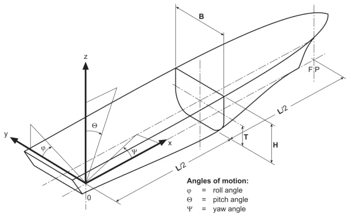
6.8 Coordinate system
For the description of the yacht's geometry the fixed, right-handed coordinate system 0, x, y, z as defined in Fig. 2.1 is introduced. The origin of the system is situated at the aft perpendicular, at centreline and on the moulded baseline at the yacht's keel. The x-axis points in longitudinal direction of the yacht positive forward, the y-axis positive to port and the z-axis positive upwards. Angular motions are considered positive in a clockwise direction about the three axes.
Q Y j y z x F P L/2 Angles of motion: j = roll angle Q = pitch angle Y = yaw angle T H B 0 L/2
Fig. 2.1 Coordinate system and angles of motion
7. Computer programs 7.1 General
7.1.1 In order to increase the flexibility in the structural design of yachts, GL also accepts direct calculations with computer programs. The aim of such analyses should be the proof of equivalence of a de-sign with the rule requirements.
7.1.2 Direct calculations may also be used to opti-mise a design; in this case only the final results are to be submitted for examination.
7.2 General programs
7.2.1 The choice of computer programs according to the "State of the Art" is free. The programs may be checked by GL through comparative calculations with predefined test examples. A generally valid approval for a computer program is, however, not given by GL. GL reserve the right to refuse computer programs. 7.2.2 Direct calculations may be applied regarding: – global strength
– longitudinal strength – beams and grillages – strength of structural details
7.2.3 For such calculations, the structural model, boundary conditions and load cases are to be agreed upon with GL.
Calculation documents are to be submitted including input and output. During the examination it may prove necessary that GL perform independent comparative calculations.
8. Workmanship
8.1 Requirements to be complied with by the manufacturer
8.1.1 Every manufacturing plant participating in a yacht project must be provided with suitable equip-ment and facilities to enable proper handling of the materials, manufacturing processes, structural compo-nents, etc. GL reserve the right to inspect the plant accordingly or to restrict the scope of manufacture to the potential available at the plant.
The manufacturing plant must have at its disposal sufficiently qualified personnel. GL must be advised of the names and areas of responsibility of all supervi-sory and control personnel. GL reserve the right to require proof of relevant qualification.
8.1.2 The shipyard or manufacturing plant and its subcontractors must get approval from GL for the type of work provided for the manufacture and installation of yachts. Approval can only be awarded if the condi-tions defined in detail in the GL Rules II – Materials and Welding are fulfilled.
8.1.3 The fabrication sites, stores and their opera-tional equipment shall comply also with the require-ments of the relevant Safety Authorities and Profes-sional Associations. The shipyard or manufacturing plant is alone responsible for compliance.
8.2 Quality control
8.2.1 It is recommended that the shipyard operates a quality assurance system, like ISO 9001 or equiva-lent.
8.2.2 As far as required and expedient, the manu-facturer’s personnel has to examine all structural com-ponents both during the manufacture and on comple-tion, to ensure that they are complete, that the dimen-sions are correct and that workmanship is satisfactory and meets the standard of good shipbuilding practice. 8.2.3 Upon inspection and corrections by the manufacturing plant, the structural components are to be shown to the GL Surveyor for inspection, in suit-able sections, normally in unpainted condition and enabling proper access for inspection.
8.2.4 The Surveyor may reject components that have not been adequately checked by the plant and may demand their re-submission upon successful completion of such checks and corrections by the plant.
9. Structural details
9.1 Details in manufacturing documents 9.1.1 All significant details concerning quality and functional ability of the components concerned shall be entered in the manufacturing documents (workshop drawings, etc.). This includes not only scantlings but, where relevant, such items as surface conditions (e.g. finishing of flame cutting edges and weld seams), and special methods of manufacture involved as well as inspection and acceptance requirements and, where relevant, permissible tolerances.
For details of welded joints see the GL Rules II – Ma-terials and Welding, Part 3 – Welding, Chapter 2 – Design, Fabrication and Inspection of Welded Joints, Annex A (Steel) and B (Aluminium).
For details of adhesive joints see the GL Rules II – Materials and Welding, Part 2 – Non-metallic Materi-als, Chapter 1 – Fibre Reinforced Plastics and Adhe-sive.
9.1.2 If, due to missing or insufficient details in the manufacturing documents, the quality or functional ability of the component cannot be guaranteed or is doubtful, GL may require appropriate improvements. This includes the provision of supplementary or addi-tional parts (for example reinforcements) even if these were not required at the time of plan approval or if - as a result of insufficient detailing - such requirement was not obvious.
9.2 Cut-outs, plate edges
9.2.1 The free edges (cut surfaces) of cut-outs, hatch corners, etc. are to be properly prepared and are to be free from notches. As a general rule, cutting drag lines, etc. must not be welded out, but are to be smoothly ground. All edges should be broken or in cases of highly stressed parts, should be rounded off. 9.2.2 Free edges on flame or machine cut plates or flanges are not to be sharp cornered and are to be finished off as laid down in 9.2.1. This also applies to cutting drag lines, etc., in particular to the upper edge of shear strake and analogously to weld joints, changes in sectional areas or similar discontinuities. 9.3 Cold forming
9.3.1 For cold forming (bending, flanging, bead-ing) of plates the minimum average bending radius should not fall short of 3 times the plate thickness t. For the welding of cold formed areas special require-ments have to be agreed.
9.3.2 In order to prevent cracking, flame cutting flash or sheering burrs must be removed before cold forming. After cold forming all structural components and, in particular, the ends of bends (plate edges) are to be examined for cracks. Except in cases where edge cracks are negligible, all cracked components are to be rejected. Repair welding is not permissible.
9.4 Assembly, alignment
9.4.1 The use of excessive force is to be avoided during the assembly of individual structural compo-nents or during the erection of sub-assemblies. As far as possible, major distortions of individual structural components should be corrected before further assem-bly.
9.4.2 Girders, beams, stiffeners, frames, etc. that are interrupted by bulkheads, decks, etc. must be accu-rately aligned. In the case of critical components, control drillings are to be made where necessary, which are then to be welded up again on completion. 9.4.3 After completion of welding, straightening and aligning must be carried out in such a manner that the material properties will not be influenced signifi-cantly. In case of doubt, GL may require a procedure test or a working test to be carried out.
9.5 Combination of different materials
9.5.1 Preventive measures are to be taken to avoid contact corrosion associated with combination of dissimilar metals with different potentials in an elec-trolyte environment, such as sea water.
9.5.2 The selection of different materials has to take into account the fact that also combination of composite materials, like fibre reinforced plastics, sandwich constructions, etc. and wood with each other or also with metals may lead to contact corrosion. 9.5.3 In addition to selecting appropriate materials, steps such as suitable insulation, an effective coating and the application of cathodic protection can be taken in order to prevent contact corrosion.
9.5.4 The selected solutions for protection have to be presented to GL for approval.
10. Corrosion protection B.6. is to be observed.
B. Materials, Corrosion Protection and Join-ing Technology
1. General
All materials to be used for the structural members mentioned in these Rules are to be in accordance with the GL Rules II – Materials and Welding, Part 1 – 3. Materials the properties of which deviate from these rule requirements may only be used upon special ap-proval by GL.
2. Steel materials and welding
2.1 Normal strength hull structural steel Normal strength hull structural steel is a hull structural steel with a minimum nominal upper yield point ReH
of 235 N/mm² and a tensile strength Rm of 400 – 520
N/mm².
2.1.1 The material factor k in the formulae of C., D., G., J. in the following is to be taken 1,0 for normal strength hull structural steel.
2.1.2 Normal strength hull structural steel is grouped into the grades GL–A, GL–B, GL–D, GL–E, which differ from each other in their toughness prop-erties. For the application of the individual grades for the hull structural members see 2.3.
2.1.3 If for special structures the use of steels with yield properties less than 235 N/mm² has been ac-cepted, the material factor k is to be determined by:
eH 235 k
R =
2.2 Higher strength hull structural steels Higher strength hull structural steel is a hull structural steel, the yield and tensile properties of which exceed those of normal strength hull structural steel. For three groups of higher strength hull structural steels the nominal upper yield stress ReH has been fixed at 315,
355 and 390 N/mm2 respectively. Where higher strength hull structural steel is used, for scantling purposes the values in Table 2.1 are to be used for the material factor k mentioned in C., D., G., J. of the following:
Table 2.1 Material factors for higher strength hull structural steel
ReH [N/mm²] k
315 0,78 355 0,72 390 0,66
For higher strength hull structural steel with other nominal yield stresses, the material factor k may be determined by the following formula:
eH 295 k R 60 = + Note
Especially when higher strength hull structural steels are used, limitation of permissible stresses due to buckling and fatigue strength criteria may be re-quired.
2.2.1 Higher strength hull structural steel is grouped into the following grades, which differ from each other in their toughness properties:
GL–A 32/36/40
GL–D 32/36/40
GL–E 32/36/40
GL–F 32/36/40
In Table 2.2 the grades of the higher strength steels are marked by the letter "H".
2.2.2 Where structural members are completely or partly made from higher strength hull structural steel, a suitable notation will be entered into the yacht's certificate.
2.2.3 In the drawings submitted for approval it is to be shown which structural members are made of higher strength hull structural steel. These drawings are to be placed on board in case any repairs are to be carried out.
2.3 Material selection for the hull 2.3.1 Material classes
For the material selection for hull structural members material classes as given in Table 2.2 are defined.
2.3.2 Material selection for longitudinal struc-tural members
Materials of the various structural members are not to be of lower grades than those obtained from the Table 2.3. Depending on the categories of structural mem-bers (Secondary, Primary and Special) for structural members not specifically mentioned in Table 2.3, grade A/AH material may generally be used. Single plate strakes within 0,4 L amidships for which class III or E/EH material is required are to have a breadth b = 800 + 5 L, max. 1 800 mm.
Table 2.2 Material classes
Thickness t [mm] 1 > 15 > 20 > 25 > 30 > 40 > 60 Material class ≤ 15 ≤ 20 ≤ 25 ≤ 30 ≤ 40 ≤ 60 ≤ 100 I II III A/AH A/AH A/AH A/AH A/AH B/AH A/AH B/AH D/DH A/AH D/DH E/EH B/AH D/DH E/EH D/DH E/EH E/EH E/EH E/EH E/EH 1 Actual thickness of the structural member.
Table 2.3 Material class or grade for longitudinal structural members
Material class or grade Structural member category
Within 0,4 L amidships Outside 0,4 L amidships Secondary:
Lower strake of longitudinal bulkhead Deck plating exposed to weather, in general Side plating
I A/AH
Primary:
Bottom plating, including keel plate Strength deck plating1
Continuous longitudinal members Upper strake in longitudinal bulkhead Vertical strake
II A/AH
Special:
Shear strake at strength deck Stringer plate in strength deck Deck strake at longitudinal bulkhead Bilge strake2
III II
(I outside 0,6 L)
1 Class III or grade E/EH to be applied in positions where high local stresses may occur.
2.3.3 Material selection for local structural members
2.3.3.1 The material selection for local structural members, which are not part of the longitudinal hull structure, may in general be effected according to Table 2.4.
Table 2.4 Material class for local structural members
Structural member Material class Face plates and webs of girder
systems II1
Rudder body 2, rudder horn, sole piece, stern frame, propeller brackets
II 1 Class I material sufficient, where rolled sections are used or
the parts are machine cut from normalized plates
2 see 2.3.3.2
2.3.3.2 Rudder body plates, which are subjected to stress concentrations (e.g. in way of lower support of semi-spade rudders), are to be of class III material. 2.3.3.3 Members not specifically mentioned, may be of class I material.
For topplates of machinery foundations located out-side 0,6 L amidships, grade A normal strength hull structural steel may also be used for thicknesses above 40 mm.
2.3.4 Structural members which are stressed in direction of their thickness
2.3.4.1 Rolled materials, which are significantly stressed in direction of their thickness, are recom-mended to be examined for doublings and non-metallic inclusions by ultrasonic testing.
2.3.4.2 In case of high local stresses in the thickness direction, e.g. due to shrinkage stresses in single bevel or double bevel T-joints with a large volume of weld metal, steels with guaranteed material properties in the thickness direction according to the GL Rules II – Materials and Welding, Part 1 – Metallic Materials, Chapter 2 – Steel and Iron Materials, Section 1, I. are to be used in order to avoid lamellar tearing.
2.4 Forged steel and cast steel
Forged steel and cast steel for stem, stern frame, rud-der post, etc. is to comply with the GL Rules II – Materials and Welding, Part 1 – Metallic Materials. The tensile strength of forged steel and of cast steel is not to be less than 400 N/mm².
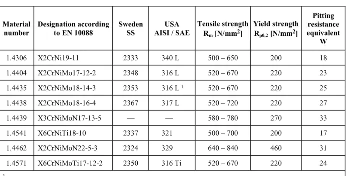
2.5 Austenitic steels
2.5.1 Stainless steels with a pitting resistance equivalent W (W = % Cr + 3,3 ⋅ % Mo) exceeding 25 are suitable for sea water without special corrosion protection, see Table 2.5.
Table 2.5 Designation and mechanical properties of austenitic stainless steels (in welded condition)
Material
number Designation according to EN 10088 SwedenSS AISI / SAE USA
Tensile strength Rm [N/mm2] Yield strength Rp0,2 [N/mm2] Pitting resistance equivalent W 1.4306 X2CrNi19-11 2333 340 L 500 – 650 200 18 1.4404 X2CrNiMo17-12-2 2348 316 L 520 – 670 220 23 1.4435 X2CrNiMo18-14-3 2353 316 L 1 520 – 670 220 25 1.4438 X2CrNiMo18-16-4 2367 317 L 520 – 720 220 27 1.4439 X3CrNiMoN17-13-5 –– –– 580 – 780 270 33 1.4541 X6CrNiTi18-10 2337 321 500 – 700 200 17 1.4462 X2CrNiMoN22-5-3 2324 329 640 – 840 460 31 1.4571 X6CrNiMoTi17-12-2 2350 316 Ti 520 – 670 220 24 1 valid for Mo > 2,5 %
2.5.2 Where austenitic steels are applied having a ratio p0,2 m R 0,5 R ≤
on special approval the 1 % proof stress Rp1,0 may be
used for scantling purposes instead of the 0,2 % proof stress Rp0,2.
2.6 Welding
The following information summarizes some principle aspects to be considered for the design of Yachts. Detailed requirements are contained in the GL Rules II – Materials and Welding, Part 3 – Welding.
2.6.1 Information contained in manufacturing documents
2.6.1.1 The shapes and dimensions of welds and, where proof by calculation is supplied, the require-ments applicable to welded joints (the weld quality grade, detail category) are to be stated in drawings and other manufacturing documents (parts lists, welding and inspection schedules). In special cases, e.g. where special materials are concerned, the documents shall also state the welding method, the welding consum-ables used, heat input and control, the weld build-up and any post-weld treatment which may be required. 2.6.1.2 Symbols and signs used to identify welded joints shall be explained if they depart from the sym-bols and definitions contained in the relevant stan-dards (e.g. DIN stanstan-dards). Where the weld prepara-tion (together with approved methods of welding) conforms both to normal shipbuilding practice and to these Rules and recognized standards, where applica-ble, no special description is needed.
2.6.2 Materials, weldability
2.6.2.1 Only base materials of proven weldability may be used for welded structures. Any approval conditions of the steel or of the procedure qualifica-tion tests and the steelmaker's recommendaqualifica-tions are to be observed.
2.6.2.2 For normal strength hull structural steels grades A, B, D and E which have been tested by GL, weldability is considered to have been proven. No measures beyond those laid down in these welding rules need therefore to be taken.
2.6.2.3 Higher strength hull structural steels grade AH/DH/EH/FH which have been approved by GL in accordance with the relevant requirements of Rules for Materials and Welding, have had their weldability examined and, provided their handling is in accor-dance with normal shipbuilding practice, may be con-sidered to be proven.
2.6.2.4 High strength (quenched and tempered) fine grain structural steels, low temperature steels, stainless
and other (alloyed) structural steels require special approval by GL. Proof of weldability of the respective steel is to be presented in connection with the welding procedure and welding consumables.
2.6.2.5 Cast steel and forged parts require testing by GL. The carbon content of components for welded structures must not exceed 0,23 % C (piece analysis not exceeding 0,25 % C).
2.6.2.6 Welding consumables used are to be suitable for the parent metal to be welded and are to be ap-proved by GL. Where filler materials having tensile properties deviating (downwards) from the parent metal are used (upon special agreement by GL) this fact must be taken into account when dimensioning the weld joints.
2.6.3 Manufacture and testing
2.6.3.1 The manufacture of welded structural com-ponents may only be carried out in workshops or plants that have been approved by GL. The require-ments that have to be observed in connection with the fabrication of welded joints are laid down in II – Materials and Welding, Part 3 – Welding.
2.6.3.2 The weld quality grade of welded joints without proof by calculation (see 2.6.1.1) depends on the significance of the welded joint for the total struc-ture and on its location in the structural element (loca-tion relative to the main stress direc(loca-tion) and on its stressing. For details concerning the type, scope and manner of testing, see Rules II – Materials and Weld-ing, Part 3 – WeldWeld-ing, Chapter 3 – Welding in the Various Fields of Application, Section 1, I.
2.6.4 General design principles
2.6.4.1 During the design stage welded joints are to be planned such as to be accessible during fabrication, to be located in the best possible position for welding and to permit the proper welding sequence to be fol-lowed.
2.6.4.2 Both the welded joints and the sequence of welding involved are to be so planned as to enable residual welding stresses to be kept to a minimum in order that no excessive deformation occurs. Welded joints should not be over dimensioned.
2.6.4.3 When planning welded joints, it must first be established that the type and grade of weld envisaged, such as full root weld penetration in the case of HV or DHV (K) weld seams, can in fact be perfectly exe-cuted under the conditions set by the limitations of the manufacturing process involved. If this is not the case, a simpler type of weld seam shall be selected and its possibly lower load bearing capacity taken into ac-count when dimensioning the component.
2.6.4.4 Highly stressed welded joints, which there-fore, are generally subject to examination, are to be so designed that the most suitable method of testing for faults can be used (radiography, ultrasonic, surface crack testing methods) in order that a reliable exami-nation may be carried out.
2.6.4.5 Special characteristics peculiar to the rial, such as the lower strength values of rolled mate-rial in the thickness direction or the softening of cold worked aluminium alloys as a result of welding, are factors which have to be taken into account when designing welded joints.
2.6.4.6 In cases where different types of material are paired and operate in sea water or any other electro-lytic medium, for example welded joints made be-tween unalloyed carbon steels and stainless steels in the wear-resistant cladding in rudder nozzles or in the cladding of rudder shafts, the resulting differences in potential greatly increase the susceptibility to corro-sion and must therefore be given special attention. Where possible, such welds are to be positioned in locations less subject to the risk of corrosion (such as the outside of tanks) or special counter-measures are to be taken (such as the provision of a protective coat-ing or cathodic protection).
2.6.5 Design details
For design details see the GL Rules Part 1 – Seagoing Ships, Chapter 1 – Hull Structures, Section 19. 3. Aluminium alloys and welding
The following information is based on the GL Rules II – Materials and Welding, Part 1 – Metallic Materials, Chapter 3 – Non-Ferrous Metals, Section 1 with the aim of summarizing aspects applicable for the design of Yachts.
3.1 General
3.1.1 The following requirements are applicable to products made from wrought aluminium alloys having a product thickness of 3 to 50 mm inclusive. Require-ments applicable to products having thicknesses out-side this range are to be specially agreed with GL. 3.1.2 Alloys and material conditions which differ from the specified requirements given below, but which conform to national standards or the manufac-turer’s material specifications may be used provided that their properties and suitability for use, and also
their weldability have been checked by GL and that GL has approved their use.
3.1.3 Alloy designations and material conditions specified herein comply with the designations of the Aluminium Association. With regard to the definition of the material conditions European standard EN 515 is applicable.
3.2 Requirements to be met by manufacturers Manufacturers wishing to supply products in accor-dance with these requirements must be approved by GL for the alloys and product forms in question. 3.3 General characteristics of products
3.3.1 The products must have a smooth surface compatible with the method of manufacture and must be free of defects liable to impair further manufactur-ing processes or the proposed application of the prod-ucts, e.g. cracks, laps, appreciable inclusions of extra-neous substances and major mechanical damage. 3.3.2 Surface defects may be repaired only by grinding provided that this is accomplished with a gentle transition to the adjacent surface of the product and that the dimensions remain within the tolerance limits. Repair by welding is not permitted. For repair purposes only tools are to be used which are exclu-sively applied for aluminium processing.
3.4 Aluminium alloys without post treatment for hardening
3.4.1 Aluminium alloys of 5000 series in 0 condi-tion (annealed) or in H111 condicondi-tion (annealed flat-tened) retain their original mechanical characteristics and therefore are not subject to a drop in mechanical strength in the welded areas.
3.4.2 These types of aluminium alloys are used for plates, strips and rolled sections and a representative list is defined in Table 2.6. This list, as well as the list of Table 2.7, is not exhaustive. Other aluminium al-loys may be considered provided the specification (manufacture, chemical composition, temper, me-chanical properties, welding, etc.) and the scope of application is submitted to GL and approved.
3.4.3 Unless otherwise specified, the Young's mo-dulus of aluminium alloys is equal to 70 000 N/mm2 and the Poisson's ratio equal to 0,33.
Table 2.6 Material condition and strength properties of plates and strips made of wrought aluminium alloys (with thickness t = 3,0 to 50 mm) 1
Alloy number Material condition Rp 0,2
min. [N/mm2] [N/mmRm 2] Material factor kAA
0/H111/H112 125 275 – 350 1,59 – 1,34 H116 215 ≥ 305 1,22 H32 215 305 – 380 1,22 – 1,07 GL-AW-5083 (AlMg4,5Mn0,7) Welded 125 275 1,59 0/H111/H112 100 240 – 310 1,87 – 1,55 H116 195 ≥ 275 1,35 H32 185 275 – 335 1,38 – 1,22 GL-AW-5086 (ALMg4) Welded 100 240 – 310 1,87 – 1,55 0/H111/H112 80 190 – 240 GL-AW-5754 (AlMg3) Welded 80 190 – 240 2,35 – 1,98 0/H111 ≥ 160 ≥ 330 1,30 H116 ≥ 260 ≥ 360 H321 ≥ 260 ≥ 360 1,02 EN-AW-5059 (AlMgMn0,8ZnZr) Welded ≥ 160 ≥ 300 1,38
1 The strength properties are applicable to both longitudinal and transverse specimens.
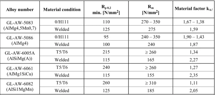
Table 2.7 Material condition and strength properties of extruded sections, bars and pipes made of wrought aluminium alloys (with thickness t = 3,0 to 50 mm) 1
Alloy number Material condition Rp 0,2
min. [N/mm2] [N/mmRm 2] Material factor kAA
0/H111 110 270 – 350 1,67 – 1,38 GL-AW-5083 (AlMg4,5Mn0,7) Welded 125 275 1,59 0/H111 95 240 – 350 1,90 – 1,43 GL-AW-5086 (AlMg4) Welded 100 240 1,87 T5/T6 215 ≥ 260 1,34 GL-AW-6005A (AlSiMg(A)) Welded 115 165 2,27 T5/T6 240 ≥ 260 1,27 GL-AW-6061 (AlMg1SiCu) Welded 115 155 2,35 T5/T6 260 ≥ 310 1,11 GL-AW-6082 (AlSi1MgMn) Welded 125 185 2,05