Electrical energy storage systems for energy networks
J. Kondoh*, I. Ishii, H. Yamaguchi, A. Murata, K. Otani, K. Sakuta,
N. Higuchi, S. Sekine, M. Kamimoto
Energy Technology Division, Electrotechnical Laboratory, 1-1-4, Umezono, Tsukuba, Ibaraki, 305-8568 Japan Received 16 October 1999; accepted 7 February 2000
Abstract
Dispersed electrical energy storage systems are expected to work for load leveling, ¯uctuation smoothing, uninterruptible power supply and emergency power source. Their introduction seems to be essential in order to control the future complicated energy utility networks. In this paper, the characteristics of promising energy storage systems by pumped hydro, compressed air, secondary batteries, superconducting magnet, ¯ywheel or capacitors have been surveyed and discussed. From the results, their characteristics and suitable application ®elds have been clari®ed. 7 2000 Elsevier Science Ltd. All rights reserved.
1. Introduction
Conventional electrical power transmission and distribution system are operated for the simple one-way transportation from remote and large power plants to consumers, but the system is just about to change, to satisfy some emerging needs. Above all, availability of bidirectional transport is necessary in order to introduce dispersed generators. This will allow us to utilize the thermal energy formerly dissipated in electric power plants and renewable energy eectively by using photovoltaics, wind turbines, fuel cell, waste-to-energy, co-generation etc. in order to reduce the impact of energy systems on the environment. Deregulation of the electrical power system is also required to reduce the electric energy charge in the competitive market. Electric power delivery not only with single but also plural quality
0196-8904/00/$ - see front matter72000 Elsevier Science Ltd. All rights reserved. PII: S0196-8904(00)00028-5
* Corresponding author. Tel.: +81-298-54-5823; fax: +81-298-54-5829. E-mail address:jkondoh@etl.go.jp (J. Kondoh).
and cost is required. For example, when it is dicult to deliver the electric power to all equipment and all customers because of the heavy load, lack of electric power generation or line fault, customers with higher quality contract are supplied preferentially. We call such coming electrical power transmission and distribution system as `energy network'. Dispersed energy storage systems as well as intelligent information technology and power electronics, will be the key technology in order to realize such sophisticated energy network. They are utilized for many signi®cant purposes in the energy network:
1. Compensation of the active power ¯uctuation which is induced by the unstable output from some kinds of dispersed generators and not fully smoothed by interconnection into the power grid;
2. Active and reactive power ¯ow control for distribution network voltage regulation. Which is necessary to interconnect the dispersed generators into the distribution network. Furthermore, they are used for high quality distribution of electrical energy as
3. Emergency power source in case of long duration outage;
4. An uninterruptible power supply for instantaneous voltage drops in case of line fault.
These four roles cannot be achieved by the remote pumped hydro energy storage system, which is the sole kind of storage system widely prevailing among all electric power systems in Japan. Furthermore, the suitable place for pumped hydro storage system is limited and alternative storage systems are desired. Some dispersed energy storage systems have the function of
5. Load leveling without usage of the crowded line since they are placed near consumers. Thus, the researches and developments of the dispersed energy storage systems have being accelerated.
In this paper, the characteristics of the energy storage systems, which are expected to be widely used in the near future, are evaluated. Some parameters of already developed storage systems are surveyed and compared with each other concerning capital cost, lifetime, output power densities, storage energy densities and losses in operation.
2. Storage systems taken for comparison
The electric energy storage systems considered in this paper are pumped hydro storage, CAES (compressed air energy storage), secondary batteries, SMES (superconducting magnetic energy storage), ¯ywheel and capacitors.
The pumped hydro storage systems occupy more than 10% of the total capacity of all power plants in Japan, and are used mainly for load leveling. The representative existing storage systems, except the pumped hydro, are shown in Table 1. Symbols A and B in Table 1 are commercial CAES plants. The lead acid battery of symbol C was demonstrated as an urban storage system with other advanced batteries in a national project. Sealed lead acid batteries of symbol D and E developed for photovoltaic power systems. Advanced batteries are demonstrated vigorously as the systems indicated F±L [1]. The SMES of symbol M was installed in a working substation and has been tested in order to con®rm its stability and reliability in the actual power systems control. System N has been developed and sold for an
UPS (uninterruptible power supply). The ¯ywheel of symbol O has been used to assist the power supply which magnetizes toroidal ®eld coils of JT-60, experimental device for a magnetically con®ned nuclear fusion reactor. System P is mainly operated in order to smooth the load of steel manufacturing plant. The ¯ywheel of symbol Q was developed as an UPS, and there was no mechanical contact during fast rotation by pivot ¯oating on lubricating oil. The rotor of ¯ywheel R is levitated using the YBCO high temperature superconductor bulks in
Table 1
Installed electrical energy storage systems
Symbol System Year Capacity Site or developer
A CAES 1978 290 MW, 4 h Huntorf, Germany
B CAES 1991 110 MW, 26 h McIntosh, Alabama, USA
C Lead acid battery 1986 1 MW, 4 MWh Tatsumi substation, Osaka, Japan
D Lead acid battery R1994 1.2 kW, 1 h Japan Storage Battery, Japan E Lead acid battery R1994 0.3 kW, 3.3 h Yuasa Battery, Japan F Sodium sulfur battery 1997 100 kW, 400 kWh Tatsumi substation, Osaka,
Japan
G Sodium sulfur battery 1998 6 MW, 8 h Tsunashima substation, Yokohama, Japan H Sodium sulfur battery
(under construction) 1999 6 MW, 8 h Ohito substation, Shizuoka,Japan
I Zinc bromine battery 1991 1 MW, 4 h Imashuku substation,
Fukuoka, Japan J Zinc bromine battery 1992 100 kW, 4 h Imashuku substation,
Fukuoka, Japan
K Redox ¯ow battery 1996 450 kW, 2 h Tatsumi substation, Osaka, Japan
L Redox ¯ow battery 1998 200 kW, 4 h Kashima-kita Electric Power, Ibaraki, Japan
M SMES 1998 1 MW, 1 kWh Imashuku substation,
Fukuoka, Japan
N SMES 1991 01 MW, 0.28 kWh Superconductivity Inc., USA
O Flywheel with conventional
bearing 1984 215 MVA, 2.2 MWh (1.1MWh available) JT-60, Ibaraki, Japan P Flywheel with conventional
bearing 1996 26.5 MVA, 129 kWh (58kWh available) Chujowan substation,Okinawa, Japan Q Flywheel with levitation
bearing 1992 5 kW, 0.23 kWh (0.115kWh available) Nagaoka Univ. of Tech.,Niigata, Japan R Flywheel with levitation
bearing 1997 1.4 kWh (1 kWh available) Chubu Electric Power, Japan S Double-layer capacitor 1997 0.25 kW, 0.933 kWh Power Systems, Yokohama,
Japan
T Double-layer capacitor 1997 3.75 kW, 0.75 kWh Power Systems, Yokohama, Japan
U Double-layer capacitor 1998 1 kW, 30 min Chubu Electric Power, Japan V Redox supercapacitor 1998 20 kW, 1 min Electrotechnical Laboratory,
order to reduce idling loss in the bearings. The double-layer capacitor of symbol S was tested to assist the power for an air conditioner. System T was designed for high output power. System U is a miniature prototype of energy storage system with large capacity double-layer capacitors for daily peak load in summer. The redox supercapacitor of symbol V seems to be easier to develop a large capacity system than the double-layer capacitor and was demonstrated by installing it on an electric vehicle.
The relationship between the output power and the output duration of the storage systems in Table 1 is shown in Fig. 1. Each storage system has a suitable range, and they can be distinguished into two types: the daily load leveling type and electric power quality improving type. Pumped hydro, CAES and batteries are suitable to level daily load ¯uctuation. The SMES and ¯ywheel with conventional bearing have a fast response and, therefore, can be utilized for the instantaneous voltage drop, ¯icker mitigation and short duration UPS. Other systems, such as, the ¯ywheel with levitation bearing, double-layer capacitor and redox supercapacitor, are promising for less than 1 h duration with small capacity.
3. Lifetime and capital cost
The lifetimes of storage systems are shown in Table 2. The cycle durability of secondary batteries is not generally high. The minimum lifetime of lead acid battery D is 2000 cycles in
Fig. 1. Output power and duration. The systems whose range are shown by solid lines have been commercially utilized. The systems whose range are shown by broken lines, are under development.
the operation of 1 h rate discharge to 40% depth and 1 h rate recharge; while that of lead acid battery E is also 2000 cycles in the operation of maximum 0.3 h rate discharge to 80% depth and 0.3 h rate recharge. These cycles decline in the usage of deeper discharge. Na/S batteries were tested to estimate their lifetime and the decrease of cell capacity was very small after more than 4500 cycles by maximum ®ve times larger current than the rated one, for about 4.5 years. Therefore, the highly reliable durability of 2250 cycles or for 15 years life (150 cycles per year) was veri®ed [6]. The lifetime of Zn/Br battery has achieved more than 1500 cycles and has planned to be improved to 3500 cycles [1]. The vanadium redox ¯ow battery with 20 kW cell stack has a record of 13,342 cycles in 2 years accelerated test [1].
The lifetime of SMES is dominated by the design against the repeated electromagnetic load and seems to be tens of years. Flywheel O has been operated for more than 21,000 cycles in 12 years from 1984 and is still in commission. The double-layer capacitor is demonstrated to have more than 50,000 cycles lifetime, by short time discharge±recharge test. People who promote the double-layer capacitor emphasize this longer lifetime than that of secondary batteries. The lifetime of redox supercapacitor system V, dominated by the ion-exchange membrane, not depends on discharge±recharge cycle number, and it is estimated at about 5 years.
The capital cost of some systems was released to the press, indicated in technical papers, or told in communication. The cost of the others was estimated using empirically derived equations with output power and storage energy.
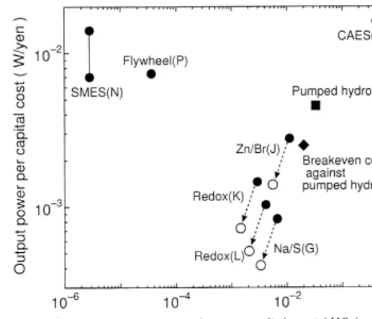
The capital cost of the pumped hydro storage system have been generally increasing with constructed yearx. The costs of the systems after 1970 in Japan are approximately indicated as
6.5(xÿ1965) thousand yen/kW [2]. Thus, the present cost is about 220 thousand yen/kW, and
it will be more expensive in the future. Roughly it is estimated at 30 thousand yen/kWh for an average output duration of about 8 h. The breakeven cost of dispersed storage systems in distribution substations for load leveling against pumped hydro was calculated about 400 thousand yen/kW [3] and 50 thousand yen/kWh. The reason of this reduction is that it is not necessary to reinforce the power transmission system.
The capital costs of smaller CAES plants are higher than those of larger plants in general. Though the capital costs of CAES are very site speci®c and may vary widely, they can be
approximated by A (US$/kW) + B (US$/kWh) h (h), where A is the output power of the
plant,B is the storage capacity and h is output duration [4]. These values ofA525 US$/kW
and B4 US$/kWh are in 1992 US dollars for a generic 150 MW output power plant with
salt caverns. Thus, the capital cost of the McIntosh plant with symbol B is estimated as 629 US$/kW.
The capital cost of Na/S battery system G is about 1.2 million yen/kW, the Zn/Br battery
Table 2
Lifetime of the electrical energy storage systems Pumped
hydro CAES Lead acidbattery Na/Sbattery Zn/Brbattery Redox ¯owbattery Flywheel Double-layercapacitor Redox super-capacitor
Years > 40 > 20 (13) 15 (10) Ð > 15 Ð 5
system J is about 360 thousand yen/kW. The vanadium redox ¯ow battery system K is about 600 thousand yen/kW, where the inverter is for 100 thousand yen/kW and the battery costs 500 thousand yen/kW. The vanadium redox ¯ow battery system L costs 970 thousand yen/kW.
The capital cost hypothesis for SMES is aSbEn, where S is the apparent power of the
converter and E is the maximum energy stored in the storage element [5]. Coecient a
196,000 US$/MVA is taken as the typical cost of a GTO converter, n = 1/3 and b = 8462
US$/J. The system Nwas of about 1 million dollars in accord with the hypothesis.
The relationship between the output power per unit capital cost and the storage energy capacity per unit capital cost of the systems is shown in Fig. 2. US$ 1 is estimated at 100 yen in the ®gure. Secondary batteries, whose lifetime are shorter, are necessary to be replaced some times within one lifetime of other storage systems. The data, when the capital cost of the secondary batteries are broadly duplicated upon considering their lifetime, are also indicated in the ®gure. It is necessary to subtract the cost of the recyclable parts and add the cost of operation and maintenance in order to estimate the practical expense.
The distribution in Fig. 2 is similar to that in Fig. 1. The CAES is inexpensive when the underground geology of the site is suitable. The capital cost of the advanced batteries (Na/S, Zn/Br, and vanadium redox ¯ow) are slightly higher than the breakeven cost against the pumped hydro, but this dierence is gradually becoming smaller. The SMES and ¯ywheel is suitable for high power and short duration use, since they are inexpensive on output power base and expensive on storage energy capacity base.
4. Output power and stored energy densities
The output power density p (W/m3) and the stored energy density e (Wh/m3) are mentioned
in this section. The power density is a rated output power divided by a volume of the storage device, and the energy density is a stored energy divided by the volume. Three kinds of the volume are considered for the calculation of these densities. One is the volume of only the
Fig. 2. Output power and storage energy capacity per capital cost of the energy storage systems are shown by the mark.. The data that the capital cost of the secondary batteries are broadly duplicated on considering their lifetime are indicated by the mark.
energy storing element, such as, a rotor and a ¯ywheel in the case of ¯ywheel energy storage system, and this is indicated by subscript 1. The second is the volume of the space for energy storage, where the rotor, the ¯ywheel, a stator armature and supporting structures are considered in the case of ¯ywheel energy storage system, and this is indicated by subscript 2. The last is the volume of the whole energy storage system, which includes inverter for example, and this is indicated by subscript 3. Naturally, the relation of these densities are p1>p2>p3
ande1>e2>e3:
The densities are shown in Fig. 3. Unfortunately, all the data for the densities cannot be
determined. The energy stored in pumped hydro plant is calculated as mgh, where m is the
mass of water, g is acceleration of gravity, andh is the eective head. The energy density e1 in
the case of h = 500 m is shown. The cavern volume in CAES of symbol B is approximately
54,000 m3, which stores about 60-atm. air and allows the plant to produce 100 MW for 26 h
continuously. Its energy density e1 against the volume of cavern, which doesn't include the
space for fuel storage, motor/generator, compressor, expanders etc, is shown. The power density p1 and energy density e1 of the 15 kWh cell of lead acid battery storage system C and
energy density of lead acid battery D and E are shown. p1 and e1 of the 484 Wh cell, and p2
and e2 of the 210 kWh module of Na/S battery storage system G are shown. p1 and e1 of the
1220 Wh cell andp2 and e2 of the 421 kWh module of Na/S battery storage system H are also
shown [1]. p2 and e2 of one 32 kW, 4 h Zn/Br battery module, the other 22 kW, 8 h Zn/Br
battery module and the redox ¯ow batteries of 100 kW, 8 h plant [1] are shown. Cell stacks, tanks for electrolyte and pump are considered for the densities of these electrolyte cycling type batteries.
p1 and e1 of toroid SMES M, the outer radius of whose superconducting magnet is 0.8 m
and aspect ratio is 2, are calculated by assuming the energy stored volume as a circular
cylinder with the radius of 1 m and the height of 1 m. The energy densitye1 of magnetic ®eld
Fig. 3. Output power densitiespand storage energy densities e.p1ande1 are shown by white bars, p2ande2 are shown by gray bars andp3ande3are shown by black bars.
B is calculated as B2= 2m
0, where m0 is the permeability in vacuum, and the value e11:8
kWh/m3 at B4 T is also shown. SMES needs not only superconducting magnets but also a
cryostat, which covers the magnet, and a refrigerator.
The stored energy of ¯ywheel is 1=2Jo2, where J is the rotational inertia and o is the
angular frequency. p1 and e1 of ¯ywheel storage systems are calculated using the volume of the
space around only the rotating materials (rotors and ¯ywheels). p2 and e2 of the ¯ywheel
system are calculated using the volume of the space assumed as a circular cylinder which surrounds not only the rotating materials but also the stator armature and supporting structures.
p1 and e1 of a double-layer capacitor unit of S, T, U and p3 and e3 of the double-layer
capacitor energy storage system U are shown.p2 and e2 of redox supercapacitor V installed in
an electric vehicle is shown.
Secondary batteries have higher energy densities than others, especially Na/S battery, which has the highest. Though the densities of the redox ¯ow battery are a little low, to duplicate the vanadium ion concentration of the electrolyte, which reduces the tank capacity by half [7]. Since a lead acid battery cannot fully discharge every time in order not to shorten its cyclic durability, its practical densities are lower than the value shown in Fig. 3.
The SMES has a poor energy density practically. The solenoid SMES can store the energy more eectively, since it produces the magnetic ®eld on the outside as well as the inside, but its placement must be considered such that the ®eld on the outside does not in¯uence the other equipment or living thing.
The power densities of ¯ywheels are high. But stator armature and supporting structure, which store no energy, need much larger space than the rotating parts since the reduction rates
of p2 and e2 from p1 and e1 are much bigger than those of the other storage systems. Thus,
considering only the energy storing parts of rotor and ¯ywheel for calculating such densities might possibly give rise to misunderstandings. Similarly, considering the storage energy density of the SMES asB2= 2m
0 causes the misunderstandings, especially when the spatially maximum
magnetic ®eld is adopted to calculate it.
The energy densities of the ¯ywheel with levitation bearings are higher than the ¯ywheel with conventional bearings, because its rotor and ¯ywheel can rotate faster.
5. Energy cycle eciency
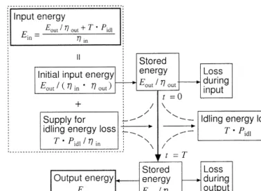
The energy ¯ow during one charge±discharge cycle is illustrated in Fig. 4, where T is the
cyclic period, Zin is the conversion eciency from commercial AC side to storage system side,
Zout is the conversion eciency from storage system side to AC side, and Pidl is the loss while the rated energy Es is stored. Pidl corresponds to the self-discharge in the case of batteries and capacitors, idling loss in the case of ¯ywheel, and refrigeration power in the case of SMES. AlthoughPidl is smaller in charging or discharging phase than rated storage phase, we regard it as a constant for simplicity. From Fig. 4, the AC terminal energy cycle eciency Ze is written as [8]:
Ze 1 Zin Zout T ts Es Eout , where ts Es=Pidl:
In case T=ts is negligible, Ze can be approximated to ZinZout: The relationship between the
eciency Ze and the cyclic period T is shown in Fig. 5. The conversion eciency of inverter
from DC to AC and from AC to DC are both assumed to be 0.95. The in¯uence of the discharge speed on the eciency of the batteries is ignored.
The slopes of some systems in Fig. 5 are derived from Pidl: The self-discharge of 0.2% per
day in the case of lead acid battery, the heater power in order to maintain the temperature of more than 3008C in the case of Na/S battery, and the self-discharge of 20% in 12 h in the case of double-layer capacitor are considered. The refrigeration power of the SMES is roughly calculated with referring to the reported data. This implies that, the refrigeration power of the
Fig. 4. Energy ¯ow during one charge±discharge cycle.
2 MWh-class low-temperature toroidal SMES is estimated at 24 kWe in case of charge and discharge periods of 1/2 h and two complete cycles per day in a reference [9]. It is roughly assumed that half of the power is dissipated by the AC loss during the charge and discharge
aecting Zin and Zout, and another half is used so as to compensate for the thermal in¯ux
aectingPidl:
Since CAES uses energy inputs both, in the form of electricity to charge the cavern during compression, and in the form of fuel to run the expanders, the conversion eciency cannot be de®ned as in the other storage methods. It is required to cope with the electric energy QZp, which would be produced if the corresponding fuel consumed in CAES is burned in another power station, whereQis the fuel energy andZp is the heat eciency of the base-load charging
plant. Thus, the two de®nitions Z1 and Z2 can be considered as the storage eciency of
CAES. Z1 EoutÿQZp=Ein is the eciency which subtracts QZp from the output energy, and
Z2Eout= EinQZp is the eciency which adds QZp to the input energy. When it is assumed
that Ein0:8 kWh for air compression and Q = 4100 Btu of fuel are needed to generate
Eout1 kWh = 3412 Btu of CAES plant output, and the base load plant has a heat eciency
Zp0:3412 [4], Z1 and Z2 are calculated to be 0.74 and 0.83, respectively. This large dierence
shows the diculty in de®ning the storage eciency in order to compare CAES with other storage systems.Z1 is adopted in Fig. 5 for the time being.
The eciency of Na/S battery becomes lower than that of the other secondary batteries when the cyclic period is longer than a few days because of the power dissipated in order to
keep its temperature more than 3008C. The eciency of ¯ywheel with conventional bearings O
declines sharply with prolonged cyclic period because of the large idling loss. The eciency of the ¯ywheel with levitation bearing R is slightly low because the power is transformed twice, in both, the discharge and charge phases, that is to say, from AC with variable voltage and variable frequency to DC and to commercial AC with constant voltage and constant frequency in discharge phase. This ¯ywheel has ordinal ball bearings for radial direction support, where
87% of Pidl is dissipated. Thus, the declining rate of the eciency with the cyclic period
becomes slow in the case of the fully levitated ¯ywheel. The reason of slightly low eciency of double-layer capacitor is derived from handling the voltage that varies with the stored energy. 6. Summary of comparison
Although the storage system with long lifetime, inexpensive cost, high density and high eciency is ideal, there is no storage system which meets all of these conditions. It is necessary to select a suitable storage system for each use.
The CAES is inexpensive as shown in Fig. 2, when the underground geology of the site is suitable. The urban CAES, which has a rather small cavern providing constant air pressure by a column water, is also proposed. This water-compensated systems need smaller size of the cavern than constant-volume systems and thereby reduces the cost of the cavern, especially in the case of unsuitable underground geology. The system installed in environs can be utilized as a cogeneration, which provides the conventionally dissipated heat of turbine and compression for local thermal demand. This urban CAES will become a popular storage system for daily load leveling with high total eciency when the cost of the cavern decreases.
The secondary batteries, which are anticipated mainly for load leveling, are the most promising substitution for pumped hydro in Japan. Their high capital cost and short cyclic durability should be improved. In order to reduce these defect by holding down the replacement cost, the technology to recycle many parts of the systems simply should be developed. Furthermore, dispersed battery energy storage systems will be important for the control of the sophisticated energy networks, as they can handle both active and reactive power almost instantaneously. Thus, their partial discharge±recharge cyclic durability must be investigated in order to utilize them for not only daily load leveling but also for more variable power operation.
The characteristics of each secondary battery are as follows. Though lead acid battery is familiar and reliable, one problem is the maintenance of re®lling water. Thus, the sealed battery, which does not need water supply, has been developed. Since Na/S battery has the highest storage energy density, as shown in Fig. 3(b), it is suitable to be installed in metropolis where the space is limited. Zn/Br battery has good proportions in the points of cost and energy density. Although the vanadium redox ¯ow battery has lower energy density than other kinds of batteries, long cyclic durability is expected, which reduces the practical capital cost, de®ned as yen/cycle, and the losses caused by self-discharge and temperature control are negligible. Furthermore, the eort to multiply the vanadium ion concentration of the electrolyte in order to reduce the tank capacity has been continued.
Although the SMES has a high power density, its energy density and storage energy capacity per unit capital cost are low. So, the SMES should be applied for the use of several seconds duration at the present moment, and the large capacity SMES for daily load leveling seems to have few advantages. The ¯ywheel with conventional bearings should be used for tens of seconds duration and less than some 10 min cyclic period, since it has a large idling loss.
However, it has high power density (kW/m3) and energy density (kWh/m3). The ¯ywheel with
levitation bearing are promising for decrease of the idling loss. But the reduction of the capital cost for levitation parts is essential. Enlargement of their capacity is also hard in the case of the ¯ywheel with levitation bearings and double-layer capacitor. Considering their higher output power density and bigger loss during energy storing than secondary batteries, they seem to be suitable for application for less than 1 h duration with small capacity, where there is no suitable device, as shown in Fig. 1, rather than the use for load leveling. However, innovative improvements on their capabilities can be expected, since they are rather new conceptions. 7. Conclusions
1. By drawing the diagram which indicates the relation between output power and duration, it has been clari®ed that each storage system has a suitable range of application. Pumped hydro, CAES and batteries are suitable to level daily load ¯uctuations. The SMES and the ¯ywheel with conventional bearings are used for high power in short duration. Other systems are promising as the storage systems for less than 1 h duration with small capacity. 2. The capital cost of CAES is estimated lower than that of the pumped hydroelectric plants.
Though the capital cost of advanced batteries is slightly higher than the break even cost against the pumped hydro, the dierence is gradually lessening. Secondary batteries, whose
lifetime are shorter than the other storage methods, are necessary to be replaced some times within one lifetime of other storage systems. The SMES and ¯ywheel is suitable for high power and short duration use, since they are expensive in storage capacity base and inexpensive in output power base.
3. Secondary batteries have higher energy densities than the others. The SMES practically has a poor energy density. The power densities of ¯ywheels are high. Considering only the energy storing parts of rotor and ¯ywheel for calculating such densities might possibly to give rise to misunderstandings, since the parts storing no energy, as stator armature and supporting structure, need larger space than the other storage systems. Considering the storage energy density of SMES as B2= 2m
0 also causes the misunderstandings, especially
when the spatially maximum magnetic ®eld is adopted to calculate it.
4. The charge±discharge cycle eciency of Na/S battery decreases than that of the other secondary batteries due to the power dissipated in self-heating when the cyclic period is longer than a few days. The eciency of ¯ywheel with conventional bearing declines suddenly with prolonging the cyclic period because of the large idling loss. The eciency of ¯ywheel with levitation bearing is slightly low because the power is transformed twice in both, the discharge and charge phases. The eciency of double-layer capacitor is slightly low because of handling the voltage which varies with the stored energy.
References
[1] Ogumi Z, et al. OHM (in Japanese) 1999;86(2):22±50.
[2] Dynamic energy system dept., In Report of workshop on wide-areal energy storage system technology (in Japanese), the Japan Society of Mechanical Engineers (JSME), 1998, 3.2-19.
[3] Shito T. OHM (in Japanese) 1995;82(7):32±7.
[4] Schainker RB, Mehta B, Pollak R. In: Proc. 55th American Power Conf. 1993. p. 992±7. [5] Therond PG, Joly I. IEEE Trans Applied Superconductivity 1993;3(1):250±3.
[6] Kodama E, Okuno A, Kiuchi F, Kurashima Y, Mima T, Mori K. Proc EESAT 1998;98:77±84.
[7] Itoh T, Kanno T, Ikeuchi A, Kawai K, Hara T, Tokuda N. In: Proc. 34th Intersociety Energy Conversion Engineering Conference, 1999-01-2616. 1999.
[8] Shimada R, Tanimoto M, Omori K, Matsukawa T. In: Papers for National Congress of IEEJ (in Japanese). 1989. p. 1505.
[9] Schoenung SM, Meier WR, Fagaly RL, Heiberger M, Stephens RB, Leuer JA, Guzman RA. In: Proc. 54th American Power Conf. 1992. p. 1511±6.