DESIGN AND SOFTWARE ARCHITECTURE OF SIP SERVER FOR OVERLOAD
CONTROL SIMULATION
Pavel O. Abaev (speaker) Yuliya V. Gaidamaka Konstantin E. Samouylov Telecommunication Systems Department Peoples’ Friendship University of Russia
Miklukho-Maklaya str., 6, 117198, Moscow, Russia Email: [email protected],
[email protected] [email protected]
Sergey Ya. Shorgin
Institute of Informatics Problems of RAS Vavilova, 44-1,
119333, Moscow, Russia Email: [email protected]
KEYWORDS
Signalling network, SIP, hop-by-hop overload control, hysteretic load control, simulation tool.
ABSTRACT
The rapid development of services provided on SIP net-works not only define the necessity of creating new equipment and standards but also requires the develop-ment of new methods and programming software tools for modeling and analyzing the effectiveness of the over-load control mechanisms in SIP-server networks. The modeling process utilizes mathematical and simulation models as well as simulators. Only simulation tools make it possible to solve problems related to the analysis and optimization of the control parameters. The most ap-propriate modeler is the simulators reflecting the pro-tocols and functions which are fully or partially built into the original system. Over the last few years, IETF working group SOC (SIP Overload Control) has been ac-tively conducting research aimed at developing an effec-tive mechanism for server overload control in SIP net-works. At present, there are no simulators for modeling the work of SIP servers in overload conditions with an application of mechanisms which are currently under de-velopment by SOC. A model for a SIP server simulator and approaches to its programming implementation are proposed in the paper.
INTRODUCTION
SIP is an application-layer signaling protocol for cre-ating, modifying, and terminating sessions with one or more participants. In November 2000, SIP was accepted as a 3GPP signaling protocol and main protocol of the IMS architecture. In 2002, recommendation (RFC 3261, 2002) which determines the current protocol form was accepted. The rapid development of the market for ser-vices based on the SIP protocol and the growing user needs have revealed a number of shortcomings in the pro-tocol, specifically, in the base overload control
mecha-nism (mechamecha-nism 503). In 2009, Rosenberg, one of the protocol designers, demonstrated in (RFC 5390, 2008) the protocols’ main shortcomings in regard to overload prevention and formulated the main requirements toward the future overload control mechanism. In mid-2010, the SOC working group was created within the IETF Committee. Its work aims at creating overload preven-tion mechanisms. The first result of their work was the document (RFC 6357, 2011) which was permanently ac-cepted in August 2011. The document provides a dis-cussion of the available types of overload control mech-anisms – local, hop-by-hop, and end-to-end, a classifi-cation of SIP networks, and presents the overall archi-tecture of overload-control systems. The SOC group’s work focuses on developing two hop-by-hop schemes for overload control as this type of mechanisms has a number of indisputable advantages over the other two types (RFC 6357, 2011; IETF draft SIP Rate Over-load Control, 2013). At present, two overOver-load control schemes have been proposed – one with flow sifting on the sender side (LBOC, Loss-based overload control) and one with restricting the flow rate of signaling messages (RBOC, Rate-based overload control). However, only the basic principles were described in SOCs’ documents and methods for calculation of the control parameters were not specified. The control parameters can be de-termined based on analysis of mathematical models or as the results of simulation modeling. As the processes go-ing on in the SIP networks are difficult to describe math-ematically and depend on a large number of different fac-tors, the task needs to be solved through the creation of a simulator.
This paper is organised as follows. We analyse IETF experience for SIP-signaling overload control problem solutions. Then we investigate overload control tech-niques which are implemented on the server and the client side. And finally, we introduce the architecture of the SIP simulation tool for modeling different overload control techniques.
Proceedings 27th European Conference on Modelling and Simulation ©ECMS Webjørn Rekdalsbakken, Robin T. Bye, Houxiang Zhang (Editors)
SIP OVERLOAD CONTROL PROBLEM OVERVIEW
Basic 503 mechanism
The SIP protocol provides a basic overload control mech-anism through the 503 (Service Unavailable) response code. SIP servers that are unable to forward a request due to temporary overload can reject the request with a 503 response. The overloaded server can insert a Retry-After header into the 503 response, which defines the number of seconds during which this server is not avail-able for receiving any further requests from the upstream neighbor. A server that receives a 503 response from a downstream neighbor stops forwarding requests to this neighbor for the specified amount of time and starts again after this time is over. Without a Retry-After header, a 503 response only affects the current request and all other requests can still be forwarded to this downstream neighbor. A server that has received a 503 response can try to resend the request to an alternate server, if one is available. A server does not forward 503 responses to-ward the UA and converts them to 500 Server Internal Error responses instead. The two possible scenarios of the mechanism 503 are shown in Fig. 1. Note that RFC 3261 provides, in the case of overload the recipient to discard incoming messages without notifying the sender.
. . .
UAc. . .
UAs Server 1 Server 2 Retry-After T Case 1 503 message Case 2 503 message + Retry-After headerFigure 1: Two scenarios of 503 mechanism A SIP server overload occurs if a SIP server does not have sufficient resources to process all incoming SIP messages. Several reasons, including Poor Capac-ity Planning, Component Failures, Avalanche Restart or Flash Crowds and the list of the problems that arise as a result of the 503 mechanism are presented in (RFC 5390, 2008).
Load Amplification. The supplementary result of the 503 mechanism is the tendency to amplify the load dur-ing periods of overload significantly, thus causdur-ing further aggravation of the problem and bringing the collapse of the network closer.
Underutilization. RFC 3261 does not cover how the 503 message recipient should react. In fact, there are some network configurations where it is not possible to clearly identify the sender of the message if the sender knows only a domain name of the cluster of receivers.
So the sender may slow down the load to the entire clus-ter of servers with no overloaded servers, but not to the actual server in overload.
The Off/On Retry-After Problem. When the sender is balancing requests between a small number of the re-ceivers, the 503 mechanism with Retry-After becomes noneffective because of its all-or-nothing technique. The 503 mechanism with Retry-After tends to cause highly oscillatory behavior under even mild overload.
Ambiguous Usages. The Standards do not clearly de-termine when the server must send the message with the code 503, and as a result of various implementations the message 503 is used to indicate different states. For ex-ample, according to (RFC 3398, 2002) the signaling gate-way sends a message 503 in response to reports of in-ability to handle the request, which does not necessarily mean that the gateway is overloaded.
Rosenberg formulated 23 requirements to overload control mechanisms in (RFC 5390, 2008); mechanisms matching them will be able to predict and to avoid or quickly to cope with an overload on the server.
Explicit Overload Control Scheme
The problem domain of SIP overload control can be split into overload control between a user agent and a SIP server and overload control between SIP servers. The first document (RFC 6357, 2011) developed by SOC, contains the overload control mechanism classification with local, hop-by-hop and end-to-end schemes, and the following network topologies for “server-server” interop-eration – load balancer, multiple sources and mesh.
Current work of the group is focused on the devel-opment of two hop-by-hop overload control schemes – Loss-based overload control and Rate-based overload control. The choice in favour of hop-by-hop mecha-nism was made because of the advantages over the other two mechanisms: the solutions implemented hop-by-hop scheme have better scalability and the scheme requires a SIP entity to aggregate overload status values of SIP servers only that each server communicates with.
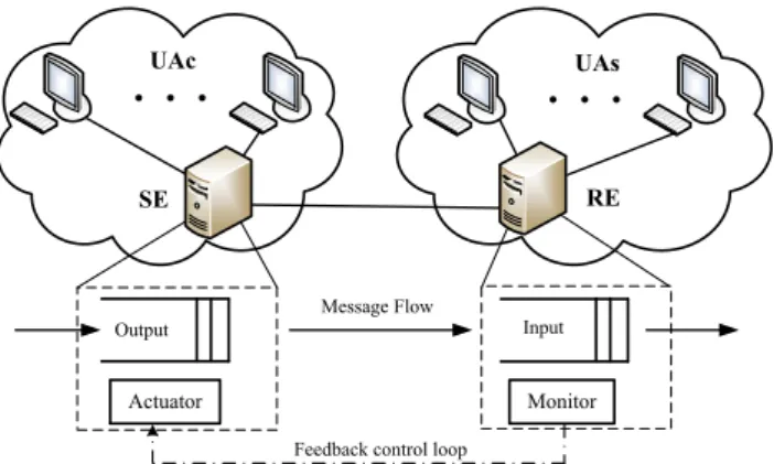
The basic idea of LBOC scheme is that the sending entity (SE) reduces the number of messages on RE’s re-quest which will be send to the receiving entity (RE) by specified in the request amount of the total number of messages. RBOC scheme operates in the following way: RE informs SE about the maximum message rate which RE would like to receive from SE within a specified pe-riod of time. RE sends the control information to SE periodically depending on RE load changes.
Both of these schemes based on the idea of feedback control loop shown in Fig. 2 between all neighboring SIP servers that directly exchange traffic. Each loop controls only two entities. The Actuator is located on the sending entity and throttles the traffic if necessary. The receiving entity has the Monitor which measures the current server load.
The four Via header parameters (‘oc’, algo’, ‘oc-validity’ and ‘oc-seq’) are introduced in (IETF draft SIP
. . .
UAc. . .
UAsSE RE
Actuator Monitor
Feedback control loop
Output Message Flow Input
Figure 2: Feedback control loop between receiving and sending entities
Overload Control, 2013) to transfer the control informa-tion between two adjacent entities.
The integer parameter ‘oc’ consisting of 10 digits and its value defines what percentage of the total number of SIP requests are subject to reduction at the SE when the loss-based scheme is used. Analogously, when the rate-based scheme is used it indicates that the client should send SIP requests at a rate of ‘oc’-value SIP re-quests or fewer per second. ‘oc-algo’ parameter de-fines the scope of algorithms supported by SE, e.g. oc-algo=”loss”, “rate”. ‘oc-validity’ parameter contains a value that indicates an interval of time (measured in mil-liseconds) that the load reduction specified in the value of the ‘oc’ parameter should be in effect, its default value is 500 ms. ‘oc-sequence’ is the sequence number associ-ated with the ‘oc’ parameter, timestamps usually use as its value.
The message format with the control information, the procedures of choice overload control algorithm, and the behavior of client and server using overload control mechanism are described in detail in (IETF draft SIP Overload Control, 2013; IETF draft SIP Rate Overload Control, 2013). However, these documents remains open the following questions that need further research:
– Criteria determining the choice of moments for sending messages with control information from SE to RE;
– Rule for choosing the value of ‘oc’ parameter; – Rule for choosing the value of ‘oc-validity’
param-eter.
To address these problems we have developed analytical models which we discuss in the next section.
OVERLOAD CONTROL TECHNIQUES OVERVIEW
Threshold Overload Control on the Server Side As a criteria determining the choice of moments for send-ing messages with control information from SE to RE we
propose to use hysteretic control technique. The system during operation changes its state depending on the to-tal number of messagesnpresent in it. Choose arbitrary numbersLandH such that0 < L < H < B, where Bis the buffer capacity. When the system starts to work it is empty,(n= 0), and as long as the total number of messages in the system remains below H −1, system is considered to be in normal state,(s= 0). When total number of messages exceedsH −1 for the first time, the system changes its state to overload, (s= 1), and RE informs SE that traffic load should be reduced: it stays in it as long as the number of messages remains betweenLandB−1. Being in overload state, RE’s sys-tem waits till the number of messages drops down below Lafter which it changes its state back to normal and in-forms SE about changes, or exceedsB −1 after which it changes its state to blocking,(s= 2), and ask SE for temporary suspension of sending SIP requests. When the total number of messages drops down belowH+ 1, sys-tem’s state changes back to overload, and RE informs SE that the process of sending of messages can be resumed with the current limitations. Input load functionλ(s, n) is schematically depicted in Fig. 3.
1 L B1 B 0 s n, n L H1 H H1 0 s 1 s s1 2 s 0 s Fl ow in te ns it y Buffer occupancy
Figure 3: Hysteretic load control with two thresholds
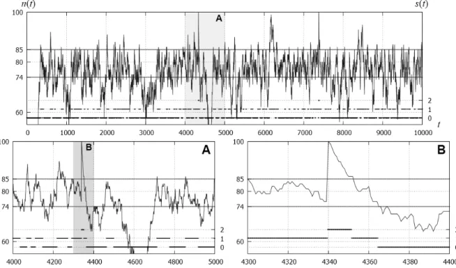
Different analytical models in the form of a queu-ing system were built to estimate the performance indi-cators of hysteretic overload control algorithm (Abaev and etc., 2012, 2013). To estimate the optimal value of the thresholds,LandH, two optimization problems were formulated and solved in (Abaev et al., SOC sim-ulation; Queueing System with Constant Service Time, 2012). In addition, such a system has been studied in the nonstationary case. The initial values of the thresh-olds were taken as a solution of the optimization prob-lem from (Abaev et al., Analytical model for optimal SOC), i.e. L = 74andH = 85. The dependency of the buffer occupancy on timetis shown in Fig. 4. The left Y-axis indicates the current buffer occupancy,n(t), and the right Y-axis indicates the overload status of the system,s(t). Server overload status changes are clearly shown in the two subfigures below the main one. Each subfigure depicts the chart to consistently zoom in on the previous figure.
Figure 4: Modeling hysteretic overload control in unsteady condition
Default Algorithm on the Client Side for LBOC case In the case of LBOC scheme the default algorithm for throttling incoming to the server traffic is used on the client side. The idea of the algorithm presented in (IETF draft SIP Overload Control, 2013) is to sift the client’s outgoing flow. Let us consider the example of the imple-mentation of the algorithm.
The client maintains two types of requests – the prior-ity and non-priorprior-ity. Prioritization of messages is done in accordance with local policies applicable to each SIP-server. In situations where the client has to sift the outgo-ing flow, it first reduces non-priority messages, and then if the buffer contains only priority messages and further reduction is still needed, the client reduces the priority messages.
Under overload condition, the client converts the value of the ‘oc’=qparameter to a value that it applies to non-priority requests. LetN1denote the number of priority
messages andN2denote the number of the non-priority
messages in the client’s buffer. The client should re-duce the non-priority messages with probability q2 =
minn1, qN1+N2
N2
o
and the priority messages with proba-bilityq1=
q(N1+N2)−q2N2
N1 if necessary to get an overall
reduction of the ‘oc’ value.
To affect the reduction rate with probabilityq2 from
the non-priority messages, the client draws a random number between 1 and 100 for the request picked from the first category. If the random number is less than or equal to converted value of the ”oc” parameter, the request is not forwarded; otherwise the request is for-warded. Recalculation of probabilities is performed
pe-riodically every 5-10 seconds by getting the value of the countersN1andN2.
Leaky Bucket Algorithm on the Client Side for RBOC case
In the case of RBOC scheme the default Leaky Bucket algorithm (ITU-T I.371, 2004) is proposed to use on the client side to deliver SIP requests at a rate specified in the ‘oc’ value with tolerance parameterτ(IETF draft SIP Rate Overload Control, 2013). The Leaky Bucket algo-rithm can be viewed as a finite capacity bucket whose real-valued content drains out at a continuous rate of 1 unit of content per time unit and whose content increases by the incrementT for each forwarded SIP request.Tis computed as the inverse of the rate specified in the ‘oc’ value, namelyT = 1/oc.
It is assumed that the client tries to put some content into the bucket at random times (time of a message ar-rival).
If at that moment the bucket capacity does not exceed the valueτ, the incoming content (incoming message) is added to the bucket and increases the volume of con-tent in the bucket byT. If at that moment the amount of content of the bucket more thanτ, the incoming content (message) is not added to the bucket.
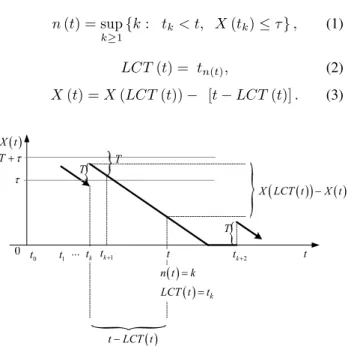
The random process of changes of the bucket’s con-tent is shown in Fig. 5. LetX(t)≥0is the value of the bucket’s content at the momentt≥0,tkis the moments
of arrival of thek−th,k≥1, message,LCT(t)is the last confirmed time before momentt,n(t)is the num-ber of the latest message accepted before the momentt.
These variables satisfy the following relations: n(t) = sup k≥1 {k: tk < t, X(tk)≤τ}, (1) LCT(t) = tn(t), (2) X(t) =X(LCT(t))− [t−LCT(t)]. (3) 0 t t1 tk t X t t 1 k t ... T
X LCT t X t
k n t k LCT t t t LCT t
T T
T 2 k tFigure 5: Changes of the value of the bucket’s content X(t)
Note that the valueτ is configured on the client side and chosen depending on the amount of the client’s mem-ory and its’ processor performance. The problem of find-ing the optimal values of the parameters ‘oc’ will not be considered in this article because of space limitations.
OSN FUNCTIONAL REQUIREMENTS
Now we present the capabilities of simulation tool OSN (Open SIP signalling Node) which is under development and supports *nix like OS. Node’s software architecture can be logically divided into three levels as shown in Fig. 6: TCP/IP Level, SIP Stack Level and Application Level.
TCP/IP Level corresponds to the first four levels of the ISO/OSI model and is implemented in OS, e.g. Debian or CentOS.
SIP Stack Level can be logically divided into two sub-levels: the first one is SIP protocol sublevel which con-sists of SIP Manager, Message Processing, and Manage-ment Entity, the second one is Traffic Load Control sub-level which consists of Actuator, Monitor and Control Function.
The SIP protocol sublevel implements SIP baseline specification (RFC 3261, 2002; RFC 3263, 2002). New modules can be added if necessary. SIP Manager imple-ments the client and server transaction state machines. Message Processing Module provides the complete set of tools for processing SIP messages. Management En-tity module is responsible for dumping and aggregation of statistics. The Traffic Load Control sublevel is detailed described in the next subsection.
Application Level contains Presence and Location Modules. The Presence module allows a party to know
the ability and willingness of other parties to participate in a call even before an attempt has been made. The mod-ule is responsible for handling Presence SUBSCRIBE requests with event package “presence” from Watchers, and enables the application to notify them about the Pres-ence status of the Presentities.
TCP/IP Stack SIP
Manager
Message Processing
Monitor Actuator Control Function ISO/OSI Layer 4 SIP Stack Application Level Management Entity Presence Location SIP Processor
Traffic Load Control
Figure 6: Architecture of the OSN simulation tool
Functional Requirements for Traffic Load Control sublevel
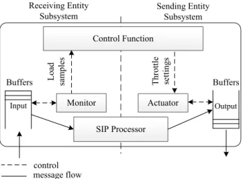
Each module of Traffic Load Control sublevel imple-ments the functionality according to (RFC 6357, 2011). The communication between the modules is shown in Fig. 7. The Monitor measures the current load of the SIP Processor on the receiving entity. It implements the mechanisms needed to determine the current usage of re-sources relevant for the SIP Processor and reports load samples to the Control Function. The Control Function implements the overload control algorithm. The Control Function uses the load samples and determines if over-load has occurred and a throttle needs to be set to adjust the load sent to the SIP Processor on the receiving entity. The Control Function on the receiving entity sends load feedback to the sending entity. The Actuator implements the algorithms needed to act on the throttles and ensures that the amount of traffic forwarded to the receiving en-tity meets the criteria of the throttle. The Actuator imple-ments the algorithms to achieve this objective, e.g., using message gapping. It also implements algorithms to select the messages that will be affected and determine whether they are rejected or redirected.
In the case of LBOC and RBOC schemes Monitor watches the server’s buffer occupancy and Control Func-tion implements hystertic overload control. Module Ac-tuator implements the default algorithm which was de-scribed above.
SUMMARY AND FURTHER STUDY
In this paper we give an overview of the problems and re-quirement analysis for SIP overload control mechanisms. We develop functional requirements for SIP simulation tool which are the result of the authors experience gained from the analytical modeling of overload control tech-niques performed by the authors in (Abaev and etc, 2012,
Control Function Monitor Receiving Entity Subsystem Sending Entity Subsystem SIP Processor Buffers
Input Actuator Output
control message flow
Load
samples Throttle settings Buffers
Figure 7: Communications between traffic control mod-ules
2013). Future work will be focused on the development technical requirements of the simulator and mathemati-cal modeling of overload control algorithms to make a proposal for the preliminary values of the control param-eters, which will be used as input data for the simulator.
Acknowledgement This work was supported in part by the Russian Foundation for Basic Research (grants 12-07-00108 and 13-07-00665).
The author thank PhD student Andrey Samuylov for modelling hysteretic overload control in unsteady condi-tion and magister Anastasia Khachko for figures design. REFERENCES
Abaev, P., Gaidamaka, Yu., Samouylov, K. 2012. Modeling of Hysteretic Signaling Load Control in Next Generation Net-works. Lecture Notes in Computer Science. Germany, Hei-delberg, Springer-Verlag. –Vol. 7469. –P.371–378.
Abaev, P., Gaidamaka, Yu., Samouylov, K. 2012. Queuing Model for Loss-Based Overload Control in a SIP Server Us-ing a Hysteretic Technique. Lecture Notes in Computer Sci-ence. Germany, Heidelberg, Springer-Verlag. -Vol. 7469. – P.440–452.
Abaev, P., Gaidamaka, Yu., Pechinkin, V., Razumchik, R., Shorgin, S. 2012. Simulation of overload control in SIP server networks. Proceedings of the 26th European Confer-ence on Modelling and Simulation, ECMS 2012. –Germany, Koblenz. –Pp. 533–539.
Abaev, P., Pechinkin, V., Razumchik, R.. 2012. Analy-sis of Queueing System with Constant Service Time for SIP Server Hop-by-Hop Overload Control. Proceedings of the 4th International Congress on Ultra Modern Telecom-munications and Control Systems, ICUMT 2012. –Saint– Petersburg, Russia. –Pp. 299–304.
Abaev, P., Pechinkin, V., Razumchik, R. 2012. On an-alytical model for optimal SIP server hop-by-hop over-load control. Communications in Computer and
Informa-tion Science: Modern Probabilistic Methods for Analy-sis of Telecommunication Networks. Germany, Heidelberg, Springer–Verlag. –Vol. 356. –P.1–10.
Abaev, P., Pechinkin, V., Razumchik, R. 2012. On Mean Re-turn Time in Queueing System with Constant Service Time and Bi-level Hysteric Policy. Communications in Computer and Information Science: Modern Probabilistic Methods for Analysis of Telecommunication Networks. Germany, Hei-delberg, Springer–Verlag. –Vol. 356. –P.11–19.
Rosenberg, J., Schulzrinne, H., Camarillo, G. et al. 2002. SIP: Session Initiation Protocol. RFC 3261.
Gurbani, V., Hilt, V., Schulzrinne, H. 2013. Session Initiation Protocol (SIP) Overload Control. draft-ietf-soc-overload-control-12.
Hilt, V., Noel, E., Shen, C., Abdelal, A. 2011. Design Consid-erations for Session Initiation Protocol (SIP) Overload Con-trol. RFC 6357.
Noel, E., Williams, P. 2012. Session Initiation Protocol (SIP) Rate Control. draft-ietf-soc-overload-rate-control-03. Rosenberg, J. 2008. Requirements for Management of
Over-load in the Session Initiation Protocol. RFC 5390.
Traffic control and congestion control in B-ISDN. ITU-T Rec-ommendation I.371. 2004.
Camarillo, G., Roach, A., Peterson, J., Ong, L. 2002. Inte-grated Services Digital Network (ISDN) User Part (ISUP) to Session Initiation Protocol (SIP) Mapping. RFC 3398. Rosenberg, J., Schulzrinne, H. 2002. Session Initiation Protocol
(SIP): Locating SIP Servers. RFC 3263.
AUTHOR BIOGRAPHIES
PAVEL O. ABAEVreceived his Ph.D. in Computer Sci-ence from the Peoples’ Friendship University of Russia in 2012. He has been a senior lecturer in the Telecommu-nication Systems department of the Peoples’ Friendship University of Russia since 2011. His current research focus is on NGN signalling, QoS analysis of SIP, and mathematical modeling of communication networks. His email address [email protected]. YULIYA V. GAIDAMAKA received the Ph.D. in Mathematics from the Peoples’ Friendship University of Russia in 2001. Since then, she has been an asso-ciate professor in the university’s Telecommunication Systems department. She is the author of more than 50 scientific and conference papers. Her research interests include SIP signalling, multiservice and P2P networks performance analysis, and OFDMA based networks. Her email address [email protected]. KONSTANTIN E. SAMOUYLOVreceived his Ph.D. from the Moscow State University and a Doctor of
Sciences degree from the Moscow Technical Univer-sity of Communications and Informatics. During 1985– 1996 he held several positions at the Faculty of Sci-ences of the Peoples’ Friendship University of Russia where he became a head of the Telecommunication Sys-tems Department in 1996. His current research inter-ests are performance analysis of 3G networks, teletraf-fic of triple play networks, and signaling networks plan-ning. He is the author of more than 100 scientific and technical papers and three books. His email address is
SERGEY YA. SHORGIN received a Doctor of Sci-ences degree in Physics and Mathematics in 1997. Since 1999, he is a Deputy Director of the Institute of Infor-matics Problems, Russian Academy of Sciences, since 2003 he is a professor. He is the author of more than 100 scientific and conference papers and coau-thor of three monographs. His research interests in-clude probability theory, modeling complex systems, ac-tuarial and financial mathematics. His email address is