ISO 9001:2008
INSTALLATION INSTRUCTIONS
FOR DOWNFLOW SINGLE STAGE GAS FURNACES WITH
CONSTANT TORQUE AIR CIRCULATING BLOWER
(-)801T DOWNFLOW SERIES
(-)(-)80DSX DOWNFLOW SERIES
U.L. and/or C.S.A. recognized fuel gas and CO (carbon monoxide) detectors are rec-ommended in all applications, and their installation should be in accordance with the manufacturer’s recommendations and/or local laws, rules, regulations, or customs.
Cont
ent
s
TABLE OF CONTENTS
1 TABLE OF CONTENTS. . . 2
2 GENERAL INFORMATION . . . 3
Receiving . . . 4
California Proposition 65 Note . . . 4
Checklist . . . 5
3 SAFETY INFORMATION. . . 6
Warnings . . . 6
Important Information About Efficiency and Quality. . 7
4 LOCATION REQUIREMENTS . . . 8
Site Selection . . . 8
Clearance – Accessibility . . . 8
Upflow Dimensions & Clearance Table . . . 9
5 DUCTING . . . 10
Downflow Installations . . . 10
6 COMBUSTION AND VENTILATION AIR . . . 12
Combustion Air Requirements . . . 12
Venting . . . 16
“B-1” Vertical Venting . . . 16
Special Vent Systems (SVS) . . . 17
Power Vent Systems . . . 18
Existing Vent Systems . . . 18
7 GAS SUPPLY. . . 19
Gas Supply and Piping. . . 19
Gas Piping . . . 20
Gas Pressure . . . 21
Setting Gas Pressure . . . 22
9 ELECTRICAL WIRING . . . 23
Reversing the Electrical Connection . . . 23
Thermostat . . . 24
8 LP CONVERSION . . . 25
10 ACCESSORIES . . . 26
Field Installed Option Accessories . . . 26
Humidifier . . . 26
4-Inch Flue Adapter . . . 26
Filters . . . 26
RXGW-B01 Chimney Adapter . . . 26
11 TWINNING . . . 27
Furnace Twinning Installations . . . 27
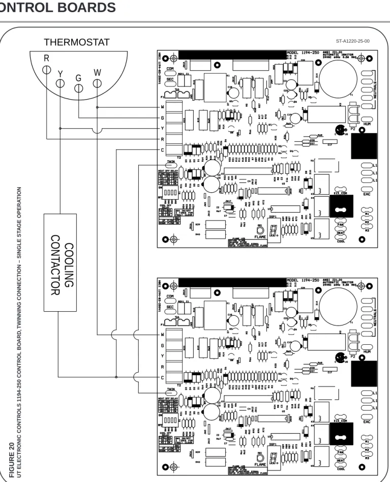
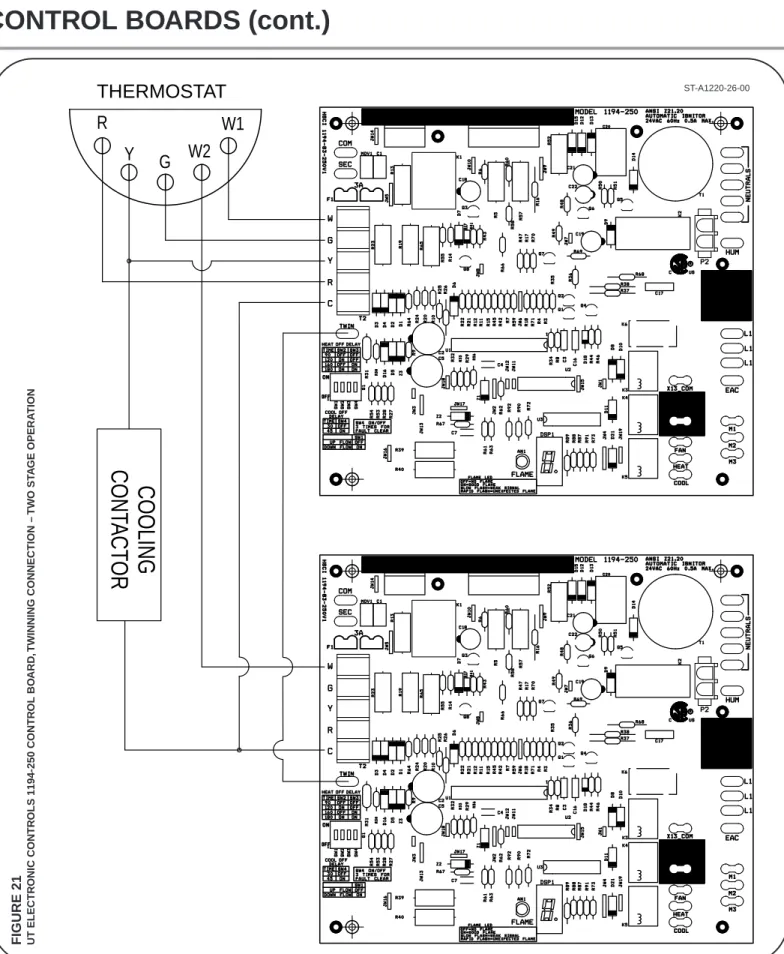
Control Boards . . . 28-29
12 HIGH ALTITUDE . . . 30
Natural Gas at High Altitudes . . . 30
LP Gas at High Altitudes. . . 32
13 STARTUP PROCEDURES . . . 33
Sequence of Operation . . . 33
14 DIAGNOSTICS & FAULT CODES . . . 34
15 LOCKOUT . . . 35
16 FIELD SELECTIONS & ADJUSTMENTS . . . 36
Field Selections – Dipswitches. . . 36
17 FAULT CLEAR . . . 37
18 FAULT RECALL . . . 37
19 FLAME STATUS L.E.D. . . 37
20 TIMING DIAGRAM. . . 37
21 ADJUSTING OR CHECKING FURNACE INPUT . 38
22 SETTING INPUT RATE . . . 39
23 AIRFLOW . . . 40
Blower Speed Selection . . . 41
24 SAFETY FEATURES . . . 42
25 MAINTENANCE. . . 43
Gas Furnace (Direct Drive) Instructions. . . 43
Filters . . . 43
Lubrication . . . 43
26 SYSTEM OPERATION INFORMATION . . . 44
27 ANNUAL INSPECTION . . . 45
28 REPLACEMENT PARTS . . . 45
24 DIAGNOSTICS. . . 46
30 WIRING DIAGRAM . . . 47
IMPORTANT: TO INSURE PROPER INSTALLATION AND OPERATION OF THIS PRODUCT, COMPLETELY READ ALL
INSTRUC-TIONS PRIOR TO ATTEMPTING TO ASSEMBLE, INSTALL, OPERATE, MAINTAIN OR REPAIR THIS PRODUCT. UPON UNPACKING OF THE FURNACE, INSPECT ALL PARTS FOR DAMAGE PRIOR TO INSTALLATION AND START-UP.
Ge
ne
ral
Inf
or
m
at
ion
GENERAL INFORMATION
NOTE: A heat loss calculation should be performed to properly determine the required furnace BTU size for the structure. Also, the duct must be properly designed and installed for proper air-flow. Existing ductwork must be inspected for proper size and to make sure that it is properly sealed. Proper airflow is necessary for both user comfort and equipment performance.
Before opening the furnace carton, verify that the data tags on the carton specify the furnace model number that was ordered from the distributor and are correct for the installation. If not, return the unit without opening the carton. If the model number is correct, open the carton and verify that the furnace rating label specifies the same furnace model number that is speci-fied on the carton label. If the model numbers do not match, re-turn the furnace to the distributor.
IMPORTANT: Proper application, installation and maintenance of this furnace and system is a must if consumers are to receive the full benefits for which they have paid.
The (-)801T/(-)(-)801DSX series furnaces are design certified by CSA for use with natural and propane gases as follows:
As a Category I furnace, it may be vented vertically with type B-1 vent pipe and also may be common vented as described in these instructions.
This furnace should be installed in accordance with the American National Standard Z223.1 - latest edition booklet entitled “National Fuel Gas Code” (NFPA 54), and the requirements or codes of the local utility or other authority having jurisdiction including local plumbing or waste water codes.
With the introduction of higher efficiency furnaces, special attention must be paid to the venting system. Only listed venting systems may be used as stated in the installation instructions and the
Na-tional Fuel Gas Code, ANSI Z223.1 (NFPA 54),. Since furnace
technology and venting requirements are changing, awareness of local, state, and federal codes and industry changes is imperative.
1. 2. 3. 4. 5. 6. 7. 8. 9. 10. 11. 12. 13. 14. 15. 16. 17. 18. JUNCTION BOX DOOR SWITCH
MAIN PRESSURE SWITCH INDUCED DRAFT BLOWER (IDB) MAIN LIMIT
BURNER FLAME SENSOR
OVER TEMPERATURE SWITCH IGNITOR GAS VALVE
GAS VALVE TRANSFORMER FLUE PIPE ENCLOSURE
HEAT ASSISTED LIMIT CONTROL (HALC) FLUE CONNECTION
CONTROL MOUNTING PLATE FURNACE CONTROL LOW VOLTAGE TERMINAL BLOWER 16 17 18 1 2 3 4 5 6 7 8 11 9 10 12 13 14 15 ST-A1220-17-00ST-A1220-17-00 FIGURE 1 FURNACE COMPONENTS
Install this furnace in accordance with the American National Stan-dard Z223.1 – latest edition entitled “National Fuel Gas Code” (NFPA54) and requirements or codes of the local utilities or other authorities having jurisdiction. This is available from the following: National Fire Protection Association, Inc.
Batterymarch Park Quincy, MA 02269
RECEIVING
Immediately upon receipt, all cartons and contents should be in-spected for transit damage. Units with damaged cartons should be opened immediately. If damage is found, it should be noted on the delivery papers, and a damage claim filed with the last carrier. • After unit has been delivered to job site, remove carton taking
care not to damage unit.
• Check the unit rating plate for unit size, electric heat, coil, volt-age, phase, etc. to be sure equipment matches what is re-quired for the job specification.
• Read the entire instructions before starting the installation. • Some building codes require extra cabinet insulation and
gas-keting when unit is installed in attic applications.
• If installed in an unconditioned space, apply caulking around the power wires, control wires, refrigerant tubing and conden-sate line where they enter the cabinet. Seal the power wires on the inside where they exit conduit opening. Caulking is re-quired to prevent air leakage into and condensate from forming inside the unit, control box, and on electrical controls.
• Install the unit in such a way as to allow necessary access to the coil/filter rack and blower/control compartment.
• Install the unit in accordance with any local code which may apply and the national codes. Latest editions are available from: “National Fire Protection Association, Inc., Batterymarch Park, Quincy, MA 02269.” These publications are:
• ANSI/NFPA No. 70-(Latest Edition) National Electrical Code. • NFPA90A Installation of Air Conditioning and Ventilating
Sys-tems.
• NFPA90B Installation of warm air heating and air conditioning systems.
• The equipment has been evaluated in accordance with the Code of Federal Regulations, Chapter XX, Part 3280.
CALIFORNIA RESIDENTS ONLY
IMPORTANT: All manufacturer products meet current Federal OSHA Guidelines for safety. California Proposition 65 warnings are required for certain products, which are not covered by the OSHA standards.
California's Proposition 65 requires warnings for products sold in California that contain, or produce, any of over 600 listed chemi-cals known to the State of California to cause cancer or birth de-fects such as fiberglass insulation, lead in brass, and combustion products from natural gas.
All “new equipment” shipped for sale in California will have labels stating that the product contains and/or produces Proposition 65 chemicals. Although we have not changed our processes, having the same label on all our products facilitates manufacturing and shipping. We cannot always know “when, or if” products will be sold in the California market.
You may receive inquiries from customers about chemicals found in, or produced by, some of our heating and air-conditioning equip-ment, or found in natural gas used with some of our products. Listed below are those chemicals and substances commonly as-sociated with similar equipment in our industry and other manu-facturers.
• Glass Wool (Fiberglass) Insulation • Carbon Monoxide (CO)
• Formaldehyde • Benzene
More details are available at the Websites for OSHA (Occupa-tional Safety and Health Administration), at www.osha.gov and the State of California's OEHHA (Office of Environmental Health Haz-ard Assessment), at www.oehha.org. Consumer education is im-portant since the chemicals and substances on the list are found in our daily lives. Most consumers are aware that products pres-ent safety and health risks, when improperly used, handled and maintained.
GENERAL INFORMATION (cont.)
Ge
ne
ral
Inf
or
m
at
ion
Installation Checklist
REFER TO INSTALLATION INSTRUCTIONS
GAS SUPPLY______ Correct pipe size (record size)
______ Correct supply pressure (during furnace operation) (record pressure) ______ Manifold pressure (record upstream pressure)
______ No gas leaks
______ L.P. Kit Number (if applicable) (record kit number) ELECTRICAL
______ 115 V.A.C. supply (Dedicated Circuit) (record voltage) ______ Polarity observed
______ Furnace properly grounded
______ Correct wire size (record type and gauge) FURNACE INSTALLATION
______ Correct clearance to combustibles (record clearance) ______ Correct clearance for service (at front) (record clearance) DUCT STATIC PRESSURE
______ in. w.c. on heating speed (record static pressure) ______ in. w.c. on cooling speed (record static pressure) ______ Air temperature rise in heat (record air temperature rise) ______ Air temperature rise in cool (record air temperature rise) VENTING
______ Correct vent pipe diameter and length (according to NFGC tables) _________________ Vent connection size ______ Correct venting material (according to NFGC tables)
______ Correct lining for masonry chimneys ______ Adequate clearance from combustibles ______ Proper negative pressure reading in the vent ______ Vent pipe secured to induced draft blower housing COMBUSTION AIR
______ Proper source of combustion air ______ Correct combustion air opening size ______ Optional attic combustion air pull ______ Non-attic combustion air pull
Che
ckl
ist
Installation Instructions remain with the furnace as a reference guide to the servicing contractor. We recommend
that performance and installation data be recorded for future reference on this sheet to meet service and warranty
obligations so that job site information is available when required.
!
WARNING
IN COMPLIANCE WITH RECOGNIZED CODES, IT IS REC-OMMENDED THAT AN AUXILIARY DRAIN PAN BE IN-STALLED UNDER THIS FURNACE AND ANY ININ-STALLED EVAPORATOR COIL THAT IS LOCATED IN ANY AREA OF A STRUCTURE WHERE DAMAGE TO THE BUILDING OR BUILDING CONTENTS MAY OCCUR AS A RESULT OF AN OVERFLOW OF THE A/C COIL DRAIN PAN.
!
WARNING
DO NOT INSTALL THIS FURNACE IN A MOBILE HOME!! THIS FURNACE IS NOT APPROVED FOR INSTALLATION IN A MOBILE HOME. DOING SO COULD CAUSE FIRE, PROPERTY DAMAGE, PERSONAL INJURY OR DEATH.
!
WARNING
INSTALL THIS FURNACE ONLY IN A LOCATION AND PO-SITION AS SPECIFIED IN THE LOCATION REQUIRE-MENTS AND CONSIDERATIONS SECTION OF THESE INSTRUCTIONS.
!
WARNING
IMPROPER INSTALLATION CAN RESULT IN UNSATISFAC-TORY OPERATION AND/OR DANGEROUS CONDITIONS AND ARE NOT COVERED BY THE MANUFACTURER’S WARRANTY.
!
WARNING
DO NOT BYPASS, JUMPER, OR REMOVE ANY SAFETY SWITCH FROM THE FURNACE CONTROL CIRCUIT. IF A SAFETY SWITCH CAUSES THE FURNACE TO SHUT DOWN OR OPERATE INTERMITTENTLY, IT IS AN INDICA-TION OF A POTENTIAL SAFETY HAZARD THAT MUST BE ADDRESSED BY A QUALIFIED TECHNICIAN, SERVICE AGENCY OR THE GAS SUPPLIER. DO NOT RESET SAFETY CONTROLS WITHOUT CORRECTIVE ACTION AND/OR VERIFICATION OF PROPER SAFE OPERATION BY A QUALIFIED INSTALLER, SERVICE AGENCY OR THE GAS SUPPLIER.
REPLACE ANY SAFETY CONTROL COMPONENT ONLY WITH IDENTICAL OEM REPLACEMENT PARTS. WHEN A NEW SAFETY SWITCH IS INSTALLED, IT MUST BE TESTED FOR A MINIMUM OF 15 MINUTES WITH THE FURNACE OPERATING AT MAXIMUM INPUT RATE AND WITH BOTH BLOWER AND BURNER DOOR INSTALLED. IF THE FURNACE IS INSTALLED IN A CLOSET, THE CLOSET DOOR MUST ALSO BE CLOSED FOR THIS TEST. REPEAT THE TEST AT THE MINIMUM INPUT RATE IF THE FURNACE IS A MULTI-STAGE FURNACE.
!
WARNING
USE ONLY WITH THE TYPE OF GAS APPROVED FOR THIS FURNACE. REFER TO THE FURNACE RATING PLATE.
!
WARNING
NEVER TEST FOR GAS LEAKS WITH AN OPEN FLAME. USE A COMMERCIALLY AVAILABLE SOAP SOLUTION MADE SPECIFICALLY FOR THE DETECTION OF LEAKS TO CHECK ALL CONNECTIONS, AS SPECIFIED IN GAS SUPPLY AND PIPING SECTION OF THESE INSTRUC-TIONS.
!
WARNING
COMBUSTION AND VENTILATION AIR MUST BE PRO-VIDED TO THE FURNACE AS REQUIRED BY THE NA-TIONAL FUEL-GAS CODE (U.S.) AND THE COMBUSTION AND VENTILATION AIR SECTION OF THESE INSTRUC-TIONS.
!
WARNING
COMBUSTION PRODUCTS MUST BE DISCHARGED OUT-DOORS. CONNECT THIS FURNACE TO AN APPROVED VENT SYSTEM ONLY, AS SPECIFIED IN THE VENT PIPE INSTALLATION SECTION OF THESE INSTRUCTIONS.
!
WARNING
WHEN A FURNACE IS INSTALLED SO THAT SUPPLY DUCTS CARRY AIR CIRCULATED BY THE FURNACE TO AREAS OUTSIDE THE SPACE CONTAINING THE FURNACE, THE RETURN AIR SHALL ALSO BE HANDLED BY DUCT(S) SEALED TO THE FURNACE CASING AND TERMINATING OUTSIDE THE SPACE CONTAINING THE FURNACE.
!
WARNING
DO NOT OPERATE THE SYSTEM WITHOUT FILTERS. A PORTION OF THE DUST ENTRAINED IN THE AIR MAY TEMPORARILY LODGE IN THE AIR DUCT RUNS AND AT THE SUPPLY REGISTERS. ANY CIRCULATED DUST PAR-TICLES WILL BE HEATED AND CHARRED BY CONTACT WITH THE FURNACE HEAT EXCHANGER. THIS SOOTY RESIDUE WILL SOIL CEILINGS, WALLS, DRAPES, CAR-PETS AND OTHER HOUSEHOLD ARTICLES. SOOT DAM-AGE MAY ALSO RESULT WITH, OR WITHOUT, FILTERS IN PLACE, WHEN CERTAIN TYPES OF CANDLES ARE BURNED, OR CANDLEWICKS ARE LEFT UNTRIMMED.
Saf
et
y Inf
or
m
at
ion
SAFETY INFORMATION
SAFETY
Saf
ety Inf
or
m
at
ion
IMPORTANT INFORMATION ABOUT
EFFICIENCY AND INDOOR AIR
QUALITY
Central cooling and heating equipment is only as efficient as the duct system that carries the cooled or heated air. To maintain effi-ciency, comfort and good indoor air quality, it is important to have the proper balance between the air being supplied to each room and the air returning to the cooling and heating equipment. Proper balance and sealing of the duct system improves the effi-ciency of the heating and air conditioning system and improves the indoor air quality of the home by reducing the amount of air-borne pollutants that enter homes from spaces where the duct-work and / or equipment is located. The manufacturer and the U.S. Environmental Protection Agency’s Energy Star Program recommend that central duct systems be checked by a qualified contractor for proper balance and sealing.
FIGURE 2
MIGRATION OF DANGEROUS SUBSTANCES, FUMES, AND ODORS INTO LIVING SPACES
Adapted from Residential Duct Diagnostics and Repair, with permission of Air Conditioning Contractors of America (ACCA).
!
WARNING
DUCT LEAKS CAN CREATE AN UNBALANCED SYSTEM AND DRAW POLLUTANTS SUCH AS DIRT, DUST, FUMES AND ODORS INTO THE HOME CAUSING PROPERTY DAMAGE. FUMES AND ODORS FROM TOXIC, VOLATILE OR FLAMMABLE CHEMICALS, AS WELL AS AUTOMO-BILE EXHAUST AND CARBON MONOXIDE (CO), CAN BE DRAWN INTO THE LIVING SPACE THROUGH LEAKING DUCTS AND UNBALANCED DUCT SYSTEMS CAUSING PERSONAL INJURY OR DEATH (SEE FIGURE 2). • IF AIR-MOVING EQUIPMENT OR DUCTWORK IS
LO-CATED IN GARAGES OR OFF-GARAGE STORAGE AREAS - ALL JOINTS, SEAMS, AND OPENINGS IN THE EQUIPMENT AND DUCT MUST BE SEALED TO LIMIT THE MIGRATION OF TOXIC FUMES AND ODORS IN-CLUDING CARBON MONOXIDE FROM MIGRATING INTO THE LIVING SPACE.
• IF AIR-MOVING EQUIPMENT OR DUCTWORK IS LO-CATED IN SPACES CONTAINING FUEL BURNING APPLIANCES SUCH AS WATER HEATERS OR BOILERS -ALL JOINTS, SEAMS, AND OPENINGS IN THE EQUIP-MENT AND DUCT MUST ALSO BE SEALED TO PRE-VENT DEPRESSURIZATION OF THE SPACE AND POSSIBLE MIGRATION OF COMBUSTION BYPROD-UCTS INCLUDING CARBON MONOXIDE INTO THE LIV-ING SPACE.
!
WARNING
ALWAYS INSTALL THE FURNACE TO OPERATE WITHIN THE FURNACE’S INTENDED TEMPERATURE-RISE RANGE WITH A DUCT SYSTEM WHICH HAS AN EXTER-NAL STATIC PRESSURE WITHIN THE ALLOWABLE RANGE, AS SPECIFIED IN THE DUCTING SECTION OF THESE INSTRUCTIONS. SEE ALSO FURNACE RATING PLATE.
THE FURNACE MAY BE USED FOR HEATING OF BUILD-INGS OR STRUCTURES UNDER CONSTRUCTION. INSTALLATION MUST COMPLY WITH ALL INSTALLATION INSTRUCTIONS INCLUDING:
PROPER VENT INSTALLATION;
-FURNACE OPERATING UNDER THERMOSTAT
-CONTROL;
RETURN AIR DUCT SEALED TO THE FURNACE;
-AIR FILTERS IN PLACE;
-SET FURNACE INPUT RATE AND TEMPERATURE
-RISE PER RATING PLATE MARKINGS; MEANS FOR PROVIDING OUTDOOR AIR
RE
-QUIRED FOR COMBUSTION;
RETURN AIR TEMPERATURE MAINTAINED
BE
-TWEEN 55°F (13°C) AND 80°F (27°C); AND CLEAN FURNACE, DUCT WORK AND
COMPO
-NENTS UPON SUBSTANTIAL COMPLETION OF THE CONSTRUCTION PROCESS, AND VERIFY THAT THE FURNACE OPERATING CONDITIONS INCLUDING IGNITION, INPUT RATE, TEMPERA-TURE RISE AND VENTING, ACCORDING TO THE INSTRUCTIONS AND CODES.
!
WARNING
BLOWER AND BURNERS MUST NEVER BE OPERATED WITHOUT THE BLOWER DOOR IN PLACE. THIS IS TO PRE-VENT DRAWING GAS FUMES (WHICH COULD CONTAIN HAZARDOUS CARBON MONOXIDE) INTO THE HOME THAT COULD RESULT IN PERSONAL INJURY OR DEATH.
GENERAL INFORMATION
LOCATION REQUIREMENTS
Loc
at
ion
1. IMPORTANT: If using a cooling evaporator coil with this fur-nace, be sure the air passes over the heat exchanger before passing over the cooling coil. The cooled air passing over the warm ambient air inside the heat exchanger tubes can cause condensation inside the tubes resulting in corrosion and even-tual failure. An auxiliary drain pan should extend under any evaporator coil installed with the furnace.
If there are manual dampers, they must be equipped to prevent heating or cooling operation unless the damper is in the full heat or cool position.
2. NOTE: This furnace is shipped with heat exchanger support brackets installed under the back of the heat exchanger. These may be removed before installation, but it is not required. 3. IMPORTANT: This furnace is not approved or recommended
for installation on its back, with access doors facing upwards.
4. This furnace is suitable for installation in buildings constructed on-site. This heating unit should be centralized with respect to the heat distribution system as much as practicable.
5. NOTE: These furnaces are approved for installation in attics, as well as alcoves, utility rooms, closets and crawlspaces. 6. IMPORTANT: Support this unit when installed. Unit may be
rein-stalled on combustible wood floorin if using a supply air plenum. If not using supply air plenum, a combustible floor base is re-quired. See ducting section of this manual.
7. IMPORTANT: If installing in a utility room, be sure the door is
wide enough to:
a. allow the largest part of the furnace to pass; or
b. allow any other appliance (such as a water heater) to pass.
SITE SELECTION
1. Select a site in the building near the center of the
pro-posed, or existing, duct system.
2. Give consideration to the vent system piping when
se-lecting the furnace location. Be sure the venting system
can get from the furnace to the termination with minimal
length and elbows.
3. Locate the furnace near the existing gas piping. Or, if
running a new gas line, locate the furnace to minimize
the length and elbows in the gas piping.
4. Locate the furnace to maintain proper clearance to
combustibles as shown in following Figure 3.
CLEARANCE – ACCESSIBILITY
The design of forced air furnaces with input ratings as
listed in the tables under Figure 3 are clearances to
com-bustible materials shown in inches.
See name/rating plate and clearance label for specific
model number and clearance information.
Service clearance of at least 24 inches (30 cm) is
recom-mended in front of all furnaces.
NOTE: Use recommended 24” (30 cm) clearance if
accessi-bility clearances are greater than fire protection clearances.
ACCESSIBILITY CLEARANCES, WHERE GREATER, MUST TAKE PRECEDENCE OVER FIRE PROTECTION CLEAR-ANCES.!
WARNING
WHEN THIS FURNACE IS INSTALLED IN A RESIDENTIAL GARAGE, IT MUST BE INSTALLED SO THE BURNERS AND IGNITION SOURCE ARE LOCATED NO LESS THAN 18 INCHES [450MM] ABOVE THE FLOOR. THIS IS TO PRE-VENT THE RISK OF IGNITING FLAMMABLE VAPORS WHICH MAY BE PRESENT IN A GARAGE. ALSO, THE FUR-NACE MUST BE LOCATED OR PROTECTED TO AVOID PHYSICAL DAMAGE BY VEHICLES. FAILURE TO FOLLOW THESE WARNINGS CAN CAUSE A FIRE OR EXPLOSION, RESULTING IN PROPERTY DAMAGE, PERSONAL INJURY OR DEATH.
!
WARNING
THIS FURNACE IS NOT APPROVED OR RECOMMENDED FOR INSTALLATION ON ITS BACK, WITH ACCESS DOORS FACING UPWARDS.
!
WARNING
DO NOT LIFT THE UNIT BY THE HEAT EXCHANGER TUBES. DOING SO CAN DAMAGE THE HEAT EX-CHANGER ASSEMBLY.
!
WARNING
COMBUSTIBLE MATERIAL MUST NOT BE PLACED ON OR AGAINST THE FURNACE JACKET. THE AREA AROUND THE FURNACE MUST BE KEPT CLEAR AND FREE OF ALL COMBUSTIBLE MATERIALS INCLUDING GASOLINE AND OTHER FLAMMABLE VAPORS AND LIQ-UIDS. PLACEMENT OF COMBUSTIBLE MATERIALS ON, AGAINST OR AROUND THE FURNACE JACKET CAN CAUSE AN EXPLOSION OR FIRE RESULTING IN PROP-ERTY DAMAGE, PERSONAL INJURY OR DEATH. THE HOMEOWNER SHOULD BE CAUTIONED THAT THE FUR-NACE AREA MUST NOT BE USED AS A BROOM CLOSET OR FOR ANY OTHER STORAGE PURPOSES.
FIGURE 3 DOWNFLOW DIMENSIONS
Loc
at
ion
R ED U C ED C LEA R A N C E ( IN .) Input A B C D E Lef t R ight B ack T op Fr ont V ent S hi p. S ide S ide W gt s. 050 14 12 27 / 32 10 3/8 ➀ 13 1/8 0 4 ➁ 0 1 3 6 ➂ 85 lbs. 070 17 1/2 16 11 / 32 12 1/8 ➀ 16 5/8 0 3 ➁ 0 1 3 6 ➂ 105 lbs. 1000 17 1/2 16 11 / 32 12 1/8 ➀ 16 5/8 0 3 ➁ 0 1 3 6 ➂ 115 lbs. 1000 21 19 27 / 32 13 7/8 ➀ 20 1/8 0 0 0 1 3 6 ➂ 120 lbs. 120 24 1/2 23 11 / 32 15 5/8 ➀ 23 5/8 0 0 0 1 3 6 ➂ 140 lbs. 150 24 1/2 23 11 / 32 15 5/8 ➀ 23 5/8 0 0 0 1 3 6 ➂ 150 lbs. T O P BO T T O M 2 4 1/2 1 9 3/ 4 C A B D L O W VO L T AG E G AS CO NNECT IO N EL ECT RI C CO NNECT IO N E S. A. R. A. 2 6 5/ 8 2 6 1 3/ 1 6 6 3/ 1 6 2 0 3/ 8 2 3 3/ 8 5/ 8 5/ 8 3/4 5/ 8 3 4 2 3 3/ 8 2 0 3/ 8 6 3/ 1 6 2 4 7 / 1 6 2 6 5 / 8 2 0 1/ 8 2 8 1 / 1 6 7/ 8 DI A. 7/ 8 DI A. 1 5/8 DI A.CL
EARANCE
T
O
CO
M
B
UST
IBL
E
M
A
T
ERI
AL
(
INCHES)
DO
WNF
L
O
W
M
O
DEL
S
NO T E: IN DO WNF L O W CO NF IG URA T IO N, O PT IO NAL AI R CUT O UT I S NO T PERM IT T ED. ➀ M ay r equir e 3” t o 4” or 3” t o 5” adapt er . ➁ M ay be 0” wit h t ype B vent . ➂ M ay be 1” wit h t ype B vent . *S ee f urnace speck sheet
f or availabilit y . SI G HT G L ASS
AI
RF
L
O
W
Proper air flow is required for the correct operation of this
furnace. Restricted air flow can cause erratic operation and
can damage the heat exchanger. The duct system must
carry the correct amount of air for heating and cooling if
summer air conditioning is used.
IMPORTANT: When using outside air, design and adjust
the system to maintain a return air temperature ABOVE
55° F during the heating season.
NOTE: Return air grilles and warm air registers must not
be obstructed or closed.
DOWNFLOW INSTALLATIONS
1. Position the unit to minimize long runs of duct or runs
of duct with many turns and elbows.
2. If summer air conditioning is desired, position the
in-door coil on the supply-air side of the unit. Ensure that
no air can bypass this coil.
3. If installing on a combustible floor and not using an
air conditioning plenum, install the special
non-com-bustible floor base. See Table 1 and Figure 5.
4. Connect the furnace to the supply air plenum. See
Fig-ure 4.
5. Connect the return air ducting to the return air opening
at the top of the unit. Make the connection air tight to
prevent the migration of toxic fumes and odors
includ-ing carbon monoxide from migratinclud-ing into the livinclud-ing
space from an adjacent fuel-burning appliance.
NOTE:
In downflow configuration, side return air cut
out is not permitted. Do not take return air from the
back of the unit.
6. If a filter is installed near the furnace, be sure to
have adequate space for installation and removal
of the unit filter.
NOTE:
DO NOT take return air from furnace rooms,
garages or cold areas. Avoid return air from utility
rooms, kitchens, laundry rooms and bathrooms.
DUCTING
Duc
ting
!
WARNING
BLOWER AND BURNERS MUST NEVER BE OPERATED WITHOUT THE BLOWER DOOR IN PLACE. THIS IS TO PREVENT DRAWING GAS FUMES (WHICH COULD CON-TAIN HAZARDOUS CARBON MONOXIDE) INTO THE HOME THAT COULD RESULT IN PERSONAL INJURY OR DEATH.
!
WARNING
SOME HEATING AIRFLOW VALUES MAY BE
HIGHER THAN THOSE REQUIRED FOR COOLING.
BE SURE TO SIZE DUCT FOR THE MAXIMUM
POS-SIBLE AIRFLOW VALUE.
SIZE AIRFLOW DISTRIBUTION SYSTEM TO
AC-CEPTABLE INDUSTRY STANDARDS AND
METH-ODS. TOTAL STATIC PRESSURE DROP OF THE AIR
DISTRIBUTION SYSTEM SHOULD NOT EXCEED .8
INCHES W.C. THIS WILL INCLUDE ANY AIR
CONDI-TIONER COIL, AIR FILTRATION SYSTEM, ZONING
SYSTEM, DUCTWORK, ETC. REFER TO ADDED
EQUIPMENT TECHNICAL INFORMATION TO OBTAIN
PRESSURE DROP INFORMATION WHEN
EQUIP-MENT IS OPERATING AT RECOMMENDED
HEAT-ING OR COOLHEAT-ING CFMS.
FIGURE 4
!
WARNING
A DOWNFLOW INSTALLATION IS CERTIFIED FOR
INSTALLATION ON A NON-COMBUSTIBLE FLOOR.
USE THE SPECIAL BASE SPECIFIED ON THE
FUR-NACE CLEARANCE LABEL. FAILURE TO INSTALL
THE SPECIAL BASE MAY RESULT IN FIRE,
PROP-ERTY DAMAGE, PERSONAL INJURY OR DEATH.
THIS BASE IS AVAILABLE AS AN ACCESSORY.
Duc
ting
DUCTING
21 5/8" COMBUSTIBLE FLOOR MATERIAL NON-COM FLOOR BASE ST-A1194-43-00 FIGURE 5NON-COMBUSTIBLE FLOOR BASE INSTALLATION INSTRUCTIONS
FLOOR CUTOUT DIMENSIONS FLOOR BASE NO. CABINET WIDTH FLOOR CUTOUT DIMENSION “A” RXGC-B14 RXGC-B17 RXGC-B21 14.0” 17.5” 21.0” 13.4” 17.0” 20.0” RXGC-B24 24.5” 23.5” A 21 5/8" FLOOR CUTOUT DIMENSIONS COMBUSTIBLE FLOOR MATERIAL NON-COM-BUSTIBLE FLOOR BASE TABLE 1
NON-COMBUSTIBLE FLOOR BASES Floor Base Size
No. Cabinet
RXGC-B14 14
RXGC-B17 17
RXGC-B21 21
Com
bust
ion Ai
r
COMBUSTION AND VENTILATION AIR
1. IMPORTANT: Air for combustion and ventilation must not
come from a corrosive atmosphere. Any failure due to corro-sive elements in the atmosphere is excluded from warranty coverage.
2. Combustion air must be free of acid forming chemicals; such as sulphur, fluorine and chlorine. These elements are found in aerosol sprays, detergents, bleaches, cleaning solvents, air fresheners, paint and varnish removers, refrigerants and many other commercial and household products. Vapors from these products when burned in a gas flame form acid compounds. The acid compounds increase the dew point temperature of the flue products and are highly corrosive after they condense. 3. The following types of installation may require OUTDOOR AIR
for combustion, due to chemical exposures: • Commercial buildings
• Buildings with indoor pools
• Furnaces installed in laundry rooms • Furnaces in hobby or craft rooms
• Furnaces installed near chemical storage areas.
4. If combustion air is exposed to the following substances (but not limited to the following), it should not be used and the fur-nace may require outdoor air for combustion.
• Permanent wave solutions • Chlorinated waxes and cleaners
• Chlorine-based swimming pool chemicals • Water softening chemicals
• De-icing salts or chemicals • Carbon tetrachloride • Halogen type refrigerants
• Cleaning solvents (such as perchloroethylene) • Printing inks, paint removers, varnishes, etc. • Hydrochloric acid
• Cements and glues
• Antistatic fabric softeners for clothes dryers • Masonry curing and acid washing materials
Combustion air requirements are determined by whether
the furnace is in an open (unconfined) area or in a
con-fined space such as a closet or small room.
When the furnace is installed in the same space with other
gas appliances, such as a water heater, be sure there is an
adequate supply of combustion and ventilation air for the
furnace and the other appliances. Do not delete or reduce
the combustion air supply required by the other gas
appli-ances in this space. See Z223.1, National Fuel Gas Code
(NFPA 54). An unconfined space must have at least 50
cubic feet (volume) for each 1,000 BTUH of the total input of
all appliances in the space. If the open space containing the
appliances is in a building with tight construction
(contempo-rary construction), outside air may still be required for the
appliances to burn and vent properly. Outside air openings
should be sized the same as for a confined space.
IMPORTANT: ONLY THE CURRENT VENT
INSTRUC-TIONS APPLY. All gas furnaces cannot be
common-vented.
OVERTEMPERATURE SAFETY
SWITCHES
Furnaces are equipped with safety switches in the burner
compartment to protect against over-temperature
condi-tions caused by inadequate combustion air supply. The
switches are located in the burner compartment. If a switch
is tripped it must be manually reset after clearing the fault
condition which caused it to open.
IMPORTANT: This is not a direct vent furnace. Review venting
instructions before installing.
!
WARNING
THIS FURNACE AND ANY OTHER FUEL-BURNING APPLI-ANCE MUST BE PROVIDED WITH ENOUGH FRESH AIR FOR PROPER COMBUSTION AND VENTILATION OF THE FLUE GASES. MOST HOMES WILL REQUIRE THAT OUT-SIDE AIR BE SUPPLIED INTO THE FURNACE AREA. FAIL-URE TO DO SO CAN CAUSE DEATH FROM CARBON MONOXIDE POISONING.
!
WARNING
ADEQUATE FACILITIES FOR PROVIDING AIR FOR COM-BUSTION AND VENTILATION MUST BE PROVIDED IN AC-CORDANCE WITH SECTION 5.3, AIR FOR COMBUSTION AND VENTILATION, OF THE NATIONAL FUEL GAS CODE, ANSI, Z223.1 LATEST EDITION OR APPLICABLE PROVI-SIONS FOR THE LOCAL BUILDING CODES, AND NOT OBSTRUCTED SO AS TO PREVENT THE FLOW OF AIR TO THE FURNACE.
COMBUSTION AIR REQUIREMENTS
!
WARNING
ALL FURNACE INSTALLATIONS MUST COMPLY WITH THE NATIONAL FUEL GAS CODE AND LOCAL CODES TO PROVIDE ADEQUATE COMBUSTION AND VENTILATION AIR FOR THE FURNACE. FAILURE TO DO SO CAN CRE-ATE HAZARDOUS CONDITIONS RESULTING IN PROP-ERTY DAMAGE, BODILY INJURY OR DEATH FROM SMOKE, FIRE OR CARBON MONOXIDE.
!
WARNING
DO NOT BYPASS, JUMPER, OR REMOVE ANY SAFETY SWITCH FROM THE FURNACE CONTROL CIRCUIT. IF A SAFETY SWITCH CAUSES THE FURNACE TO SHUT DOWN OR OPERATE INTERMITTENTLY, IT IS AN INDICA-TION OF A POTENTIAL SAFETY HAZARD THAT MUST BE ADDRESSED BY A QUALIFIED TECHNICIAN, SERVICE AGENCY OR THE GAS SUPPLIER. DO NOT RESET SAFETY CONTROLS WITHOUT CORRECTIVE ACTION AND/OR VERIFICATION OF PROPER SAFE OPERATION BY A QUALIFIED INSTALLER, SERVICE AGENCY OR THE GAS SUPPLIER.
REPLACE ANY SAFETY CONTROL COMPONENT WITH IDENTICAL OEM REPLACEMENT PARTS ONLY.
COMBUSTION AND VENTILATION AIR (cont.)
Com
bust
ion Ai
r
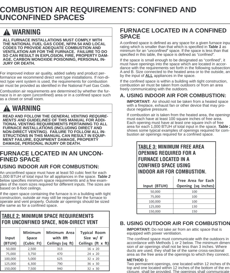
For improved indoor air quality, added safety and product per-formance we recommend direct vent type installations. If non-di-rect type vent system is used, the requirements for combustion air must be provided as identified in the National Fuel Gas Code. Combustion air requirements are determined by whether the fur-nace is in an open (unconfined) area or in a confined space such as a closet or small room.
FURNACE LOCATED IN AN
UNCON-FINED SPACE
USING INDOOR AIR FOR COMBUSTION:
An unconfined space must have at least 50 cubic feet for each 1,000 BTUH of total input for all appliances in the space. Table 2 below specifies minimum space requirements and a few exam-ples of the room sizes required for different inputs. The sizes are based on 8-foot ceilings.
If the open space containing the furnace is in a building with tight construction, outside air may still be required for the furnace to operate and vent properly. Outside air openings should be sized the same as for a confined space.
FURNACE LOCATED IN A CONFINED
SPACE
A confined space is defined as any space for a given furnace input rating which is smaller than that which is specified in Table 1 as minimum for an “unconfined” space. If the space is less than that specified in this table, the space is defined as “confined”. If the space is small enough to be designated as “confined”, it must have openings into the space which are located in accor-dance with the requirements set forth in the following subsections A and B. Size connected to the heated area or to the outside, and by the input of ALL appliances in the space.
If the confined space is within a building with tight construction, combustion air must be taken from outdoors or from an area freely communicating with the outdoors.
A. USING INDOOR AIR FOR COMBUSTION:
IMPORTANT: Air should not be taken from a heated space with a fireplace, exhaust fan or other device that may pro-duce negative pressure.
If combustion air is taken from the heated area, the openings must each have at least 100 square inches of free area. Each opening must have at least one square inch of free area for each 1,000 BTUH of total input in the space. Table 3 shows some typical examples of openings required for com-bustion air openings required for a confined space.
B. USING OUTDOOR AIR FOR COMBUSTION:
IMPORTANT: Do not take air from an attic space that is equipped with power ventilation.
The confined space must communicate with the outdoors in accordance with Methods 1 or 2 below. The minimum dimen-sion of air openings shall not be less than 3 inches. Where ducts are used, they shall be of the same cross-sectional area as the free area of the openings to which they connect. METHOD 1:
Two permanent openings, one located within 12 inches of the top and one located within 12 inches of the bottom of the en-closure, shall be provided. The openings shall communicate directly, or by ducts, with the outdoors or spaces (crawl or attic) that freely communicate with the outdoors.
COMBUSTION AIR REQUIREMENTS: CONFINED AND
UNCONFINED SPACES
!
WARNING
ALL FURNACE INSTALLATIONS MUST COMPLY WITH THE NATIONAL FUEL GAS CODE, NFPA 54 AND LOCAL CODES TO PROVIDE ADEQUATE COMBUSTION AND VENTILATION AIR FOR THE FURNACE. FAILURE TO DO SO CAN RESULT IN EXPLOSION, FIRE, PROPERTY DAM-AGE, CARBON MONOXIDE POISONING, PERSONAL IN-JURY OR DEATH.
!
WARNING
READ AND FOLLOW THE GENERAL VENTING
REQUIRE-MENTS AND GUIDELINES OF THIS MANUAL FOR
ADDI-TIONAL VENTING REQUIREMENTS PERTAINING TO ALL FURNACE INSTALLATIONS (INCLUDING DIRECT AND NON-DIRECT VENTING). FAILURE TO FOLLOW ALL IN-STRUCTIONS IN THIS MANUAL CAN RESULT IN EQUIP-MENT FAILURE, EQUIPEQUIP-MENT DAMAGE, PROPERTY DAMAGE, PERSONAL INJURY OR DEATH.
TABLE 7:
MINIMUM SPACE REQUIREMENTS
FOR UNCONFINED SPACE, NON-DIRECT VENT*
Input (BTUH) Minimum Space (Cubic Ft) Minimum Area with 8 Ceilings (sq ) Typical Room Size w/ 8' Ceilings ( x ) 50,000 2,500 313 16 x 20 75,000 3,750 470 24 x 20 100,000 5,000 625 32 x 20 125,000 6,300 790 36 x 30 150,000 7,500 940 32 x 30
TABLE 2: MINIMUM SPACE REQUIREMENTS
FOR UNCONFINED SPACE, NON-DIRECT VENT
30
TABLE 8: MINIMUM FREE AREA
OPENING REQUIRED FOR A
FURNACE LOCATED IN A
CONFINED SPACE USING
INDOOR AIR FOR COMBUSTION.
Input (BTUH)
Free Area for Each Opening (sq inches) 50,000 100 75,000 100 100,000 100 125,000 130 150,000 150
TABLE 3: MINIMUM FREE AREA
OPENING REQUIRED FOR A
FURNACE LOCATED IN A
CONFINED SPACE USING
Com
bust
ion Ai
r
COMBUSTION AND VENTILATION AIR (cont.)
A. Where directly communicating with the outdoors through an opening or where communicating to the outdoors through vertical ducts as shown in Figure 7, each opening shall have a minimum free area of 1 square inch for each 4,000 BTUH of total appliance input rating of all equipment in the enclo-sure. Table 4 specifies the minimum area for each of the 2 combustion air openings and minimum round duct diameter for direct openings and vertical ducting only.
B. Where communicating with the outdoors through horizon-tal ducts, each opening shall have a minimum free area of 1 square inch for each 2,000 BTUH of total appliance input rat-ing of all equipment in the enclosure (see Figure 8). Table 5
specifies the minimum area for each of the 2 combustion air openings and minimum round duct diameter for horizontal ducting only.
METHOD 2:
One permanent opening located within 12 inches of the top of the enclosure, shall be permitted where the equipment has clearances of at least 1 inch from the sides and back and 6 inches from the front of the appliance. The opening shall di-rectly communicate with the outdoors or communicate through a vertical or horizontal duct to the outdoors or spaces (crawl or attic) that freely communicate with the outdoors, and shall have a minimum of:
TABLE 9 : MINIMUM FREE AREA REQUIRED
FOR EACH OPENING (WHEN TWO OPENINGS
ARE USED) WITH A FURNACE:
1. LOCATED IN A CONFINED SPACE
2. USING OUTDOOR AIR FOR COMBUSTION
3. COMMUNICATING DIRECTLY TO THE
OUTSIDE THROUGH AN OPENING OR
THROUGH A VERTICAL VENT DUCT.*
Total Input forALL Gas Appliances
(BTUH)
Free Area for Each Opening when 2 Separate
Openings are used (sq inches)
Round Pipe Duct Diameter ( Ver cal Duct Only) (inches)
50,000 13 5 75,000 19 5 100,000 25 6 125,000 32 8 150,000 38 8
TABLE 4: MINIMUM FREE AREA REQUIRED
FOR EACH OPENING (WHEN TWO OPENINGS
ARE USED) WITH A FURNACE:
1. LOCATED IN A CONFINED SPACE
2. USING OUTDOOR AIR FOR COMBUSTION
3. COMMUNICATING DIRECTLY TO THE
3.
OUTSIDE THROUGH AN OPENING OR
3.
THROUGH A VERTICAL DUCT.
TABLE 1 0: MINIMUM FREE AREA REQUIRED
FOR EACH OPENING (WHEN TWO OPENINGS
ARE USED) WITH A FURNACE:
1. LOCATED IN A CONFINED SPACE
2. USING OUTDOOR AIR FOR COMBUSTION
3. COMMUNICATING DIRECTLY TO THE
OUTSIDE THROUGH A H ORIZONTAL DUCT.
Total Input forALL Gas Appliances
(BTUH)
Free Area for Each Opening when 2 Separate
Openings are used (sq inches)
Round Pipe Duct Diameter (Horizontal Duct Only) (inches) 50,000 25 6 75,000 38 8 100,000 50 8 125,000 63 10 150,000 75 10
TABLE 5: MINIMUM FREE AREA REQUIRED
FOR EACH OPENING (WHEN TWO OPENINGS
ARE USED) WITH A FURNACE:
1. LOCATED IN A CONFINED SPACE
2. USING OUTDOOR AIR FOR COMBUSTION
3. COMMUNICATING DIRECTLY TO THE
3.
OUTSIDE THROUGH A HORIZONTAL DUCT.
TABLE 1 1: MINIMUM FREE AREA REQUIRED
FOR AN OPENING (WHEN O N
E OPENING IS
USED) WITH A FURNACE:
1. LOCATED IN A CONFINED SPACE
2. USING OUTDOOR AIR FOR COMBUSTION
3. COMMUNICATING DIRECTLY TO THE
*
Total Input forALL Gas Appliances
(BTUH)
Free Area for an Opening when 1 Opening is used
(sq inches)
Round Pipe Duct Diameter (inches) 50,000 25 6 75,000 38 8 100,000 50 8 125,000 63 10 150,000 75 10
OUTSIDE.
TABLE 6: MINIMUM FREE AREA REQUIRED
FOR EACH OPENING (WHEN TWO OPENINGS
ARE USED) WITH A FURNACE:
1. LOCATED IN A CONFINED SPACE
2. USING OUTDOOR AIR FOR COMBUSTION
3. COMMUNICATING DIRECTLY TO THE
3.
OUTSIDE THROUGH A HORIZONTAL DUCT.
COMBUSTION AIR REQUIREMENTS: CONFINED AND
UNCONFINED SPACES
GAS WATER HEATER FURNACE 12” MAX 12” MAX NOTE:EACH OPENING SHALL HAVE A FREE AREA OF NOT LESS THAN ONE SQUARE INCH PER 1,000 BTU PER HOUR OF THE TOTAL INPUT RATING OF ALL EQUIPMENT IN THE ENCLOSURE, BUT NOT LESS THAN 100 SQUARE INCHES. AIR FROM HEATED SPACE
FIGURE 6
AIR FROM HEATED SPACE
COMBUSTION AND VENTILATION AIR (cont.)
Com
bust
ion Ai
r
A. 1 Square inch for each 3,000 BTUH of the total input rat-ing of all equipment located in the enclosure
and
B. Not less than the sum of the areas of all vent connectors in the confined space.
If the unit is installed where there is an exhaust fan, sufficient ventilation must be provided to prevent the exhaust fan from cre-ating negative pressure.
It is also acceptable to run the condensate drain (or refriger-ant) line access over the air intake hole as long as a 1" mini-mum clearance is maintained.
Combustion air openings must not be restricted in any manner. IMPORTANT: When indoor combustion air is used, the inlet air opening at the furnace must be protected from accidental block-age.
IMPORTANT: If the furnace is in a location with an exhaust fan,
there must be sufficient ventilation to prevent the exhaust fan from creating a negative pressure in the room.
Combustion air openings must NOT BE RESTRICTED in any manner.
CONSULT LOCAL CODES FOR SPECIAL REQUIREMENTS. B: Method 3
For the optimum in quiet operation, attic air may be brought di-rectly to the furnace.
IMPORTANT: In applications using Method 3 for combustion air, the attic must be ventilated by gable or soffit vents.
COMBUSTION AIR REQUIREMENTS: CONFINED AND
UNCONFINED SPACES
GAS WATER
HEATER FURNACE
OPTIONAL
1 SQ. INCH PER 4000 BTUH INLET
AIR GABLE VENT VENTILATED ATTIC GABLE OR SOFFIT VENTS OUTLET AIR IN ATTIC MUST BE ABOVE INSULATION 1 SQ. INCH PER 4000 BTUH INLET AIR
12” MAX 1 SQ. INCH PER 4000 BTUH OUTLET AIR GAS WATER HEATER FURNACE 12” MAX
INLET AIR 1 SQ. INCH PER 2000 BTUH OUTLET AIR 1 SQ. INCH
PER 2000 BTUH OUTLET AIR 1 SQ. INCH PER 4000 BTUH INLET AIR 1 SQ. INCH PER 4000 BTUH ST-A1227-03 ST-A1227-02 FIGURE 7 NON-DIRECT VENT AIR FROM ATTIC OR CRAWL SPACE FIGURE 8 NON-DIRECT VENT OUTSIDE AIR USING A HORIZONTAL DUCT VENT PENETRATIONS
FORNONDIRECTVENTFURNACES AIR FROM ATTIC/CRAWL SPACE
VENT PENETRATIONS
FORNONDIRECTVENTFURNACES
Com
bust
ion Ai
r
COMBUSTION AND VENTILATION AIR (cont.)
GENERAL INFORMATION
The furnace must be vented in accordance with these instructions, National Fuel Gas Code, ANSI Z223.1 and requirements or codes of the local utility or other authority having jurisdiction.
DRAFT INDUCER
FURNACE CATEGORY INFORMATION
This furnace is shipped as a Category Itype induced draft fur-nace. A Category Ifurnace operates with a nonpositive vent pres-sure and has a vent gas temperature at least 140°F above the dew point of the vent gases. A Category Itype may be a draft hood equipped furnace or have a fan assisted combustion sys-tem (induced draft). The inducer is used to pull flue products through the combustion chamber and as they leave the furnace, most of the energy has been dissipated. The buoyant effect of the flue gases provides venting to the outdoors.
During the off cycle, the inducer is off and there is very little flow through the vent, cooling the vent. During the on cycle there is no dilution airflow, as with a draft hood type furnace. Although the vent heats up rapidly without dilution air, the flue products contain more water vapor, which results in a higher dew point tempera-ture. It is most important that you follow the guidelines in these instructions to prevent the possible formation of condensation in the venting system.
As a Category Ifurnace it may be vented vertically with type B-1 vent pipe and also may be common vented, as described in these instructions.
IMPORTANT APPLICATION NOTES
When the furnace is used as a replacement, the existing vent system should be inspected to assure that there are no obstruc-tions, blockage, or any signs of corrosion and is properly sized for use with this furnace.
NOTE: When the vent table permits more than one diameter of pipe for a connector or vent, the smallest permitted diameter must be used.
Vent pipe may be type “B-1,” either rigid or suitable flexible con-struction that carries a U.L. listing.
Common venting is allowed with vertical B-1 vent systems, and lined masonry chimneys. Follow the National Fuel Gas Code, ANSI Z223.1 for proper installation practices.
NOTE: Follow combustion air instructions as outlined in this man-ual.
Single wall vent connectors to “B-1 vent or masonry chimneys” may be used under the guidelines of the National Fuel Gas Code, ANSI Z223.1.
The entire length of the vent connector shall be readily ac-cessible for inspection, cleaning and replacement.
“B-1” VERTICAL VENTING
NOTE: Refer to the National Fuel Gas Code, ANSI Z223.1. Type “B-1” vents must be installed in accordance with the terms of their listings and the vent manufacturer’s instructions. “B-1” vents must be supported and spaced in accordance with their listings and the manufacturer’s instructions. All vents must be supported to maintain their minimum clearances from com-bustible material.
*NOTE: All furnaces have a 3” vent connection as shipped from the fac-tory. A 3” to 4” or 3” to 5” vent transition may be required when vertically vented or common vented with metal vent pipes. THE VENT
TRANSI-TION CONNECTRANSI-TION MUST BE MADE AT THE FURNACE VENT EXIT. It
must originate with an adapter if required, at the furnace flue collar and terminate either in a listed cap or roof assembly. When common venting, the vent connector size may differ from the above diameters depending on application. See National Fuel Gas Code ANSI Z223.1 or latest edition tables.
!
WARNING
DEVICES ATTACHED TO THE FLUE OR VENT FOR THE PURPOSE OF REDUCING HEAT LOSS UP THE CHIMNEY HAVE NOT BEEN TESTED AND HAVE NOT BEEN IN-CLUDED IN THE DESIGN CERTIFICATION OF THIS FUR-NACE. WE, THE MANUFACTURER, CANNOT AND WILL NOT BE RESPONSIBLE FOR INJURY OR DAMAGE CAUSED BY THE USE OF SUCH UNTESTED AND/OR UN-CERTIFIED DEVICES, ACCESSORIES OR COMPONENTS.
!
WARNING
VENT PIPE ATTACHING HOLES MUST BE PREDRILLED IN THE 1/8” DIAMETER HOLES THROUGH THE VENT PIPE AND COLLAR AND USE #8 SCREWS TO ATTACH. SEE FIGURE 10. FAILURE TO FOLLOW THIS WARNING CAN CAUSE RECIRCULATION OF FLUE PRODUCTS CAUSING CARBON MONOXIDE POISONING RESULTING IN PER-SONAL INJURY OR DEATH.
VENTING
VERTICAL VENTING Categorized Furnace Vent Input Size Recommended (See NFGC) 50K 3” 75K *4” 100K *4” 125K *5” 150K *5”
COMBUSTION AND VENTILATION AIR (cont.)
VERTICAL VENT SYSTEMS:
1. A gas vent shall terminate above the roof surface with a listed cap or listed roof assembly. Gas vents 12 inches in size or smaller with listed caps shall be permitted to be terminated in accordance with Figure 9, provided they are at least 8 feet from a vertical wall or similar obstruction. All other gas vents shall terminate not less than 2 feet above the highest point where they pass through the roof and at least 2 feet higher than any portion of a building within 10 feet.
2. A type B-1 gas vent shall terminate at least 5 feet in vertical height above the highest connected equipment draft hood or flue collar.
3. Must rise 1/
4” per foot away from the furnace on horizontal runs
and be supported with straps or hangers so it has no sags or dips. Supports at 4 foot intervals and at all elbows are recom-mended.
4. The vent connector must be mechanically fastened to the flue outlet of the furnace with at least (2) sheet metal screws ex-cept vent connectors that are B-1 material. These shall be as-sembled in accordance with the manufacturer’s instructions. See Figure 10.
5. Any angle greater than 45 degrees from the vertical is consid-ered horizontal. The total horizontal distance of a vent plus the horizontal vent connector serving draft-hood equipped appli-ances shall not be greater than 75 percent of the vertical height of the vent.
Single appliance venting of a fan assisted furnace into a tile-lined masonry chimney is prohibited. The chimney must be lined with either Type B vent or with a listed, single wall system. Reference National Fuel Gas Code, ANSI Z223.1. See Figure 11 for typical B-1 vent chase.
SPECIAL VENT SYSTEMS (SVS)
IMPORTANT: It is THE FURNACE MANUFACTURER’s position
now that new installations of any HTPV pipe used in a category
IIIvent application, including Selkirk’s Selvent™ IIHTPV prod-uct, should cease immediately.
!
WARNING
DO NOT CONNECT THIS FURNACE TO A CHIMNEY USED TO VENT A SOLID FUEL APPLIANCE (WOOD OR COAL). VENTING WITH A SOLID FUEL APPLIANCE CAN LEAD TO IMPROPER FUNCTIONING OF THE UNIT, AND DUE TO SOOTING, THE POSSIBILITY OF FIRE RESULTING IN PROPERTY DAMAGE, PERSONAL INJURY OR DEATH.
VENT PIPE FLUE PIPE PRE-DRILL ATTACHING HOLES FIGURE 17 ST-A1227-05 FIGURE 10
ATTACHING TO FLUE PIPE AT UNIT OUTLET
LISTED CAP
LISTED GAS VENT
ROOF PITCH = X/12 12
X
“H” - MINIMUM ALLOWABLE HEIGHT FROM ROOF TO DISCHARGE OPENING
F
ROOF PITCH “H” (MIN.) FT.
FLAT TO 6/12 1.0 OVER 6/12 TO 7/12 1.25 OVER 7/12 TO 8/12 1.5 OVER 8/12 TO 9/12 2.0 OVER 9/12 TO 10/12 2.5 OVER 10/12 TO 11/12 3.25 OVER 11/12 TO 12/12 4.0 OVER 12/12 TO 14/12 5.0 OVER 14/12 TO 16/12 6.0 OVER 16/12 TO 18/12 7.0 OVER 18/12 TO 20/12 7.5 OVER 20/12 TO 21/12 8.0 ST-A1220-24 FIGURE 9
TYPICAL VENTING WITH “B-1” VENT
ST-A1220-24
Com
bust
ion Ai
COMBUSTION AND VENTILATION AIR (cont.)
POWER VENT SYSTEMS
When vertical venting is not possible, the only acceptable method for horizontal venting is with the use of Tjernlund model GPAK-1TR or Field Controls models SWG-4R power venter. Type B vent pipe and fittings must be used. Common venting is not per-mitted
All application and installation instructions supplied with the power venter must be followed.
Please address all questions regarding power venter installation, agency listings and furnace model compatibility to:
Tjernlund Products, Inc.
(800) 255-4208 or (612) 426-2993 Field Controls L.L.C.
(800) 742-8368 or (919) 522-0214
EXISTING VENT SYSTEMS
IMPORTANT RETROFIT
VENTING INSTRUCTIONS
If this furnace is a replacement installation, ALWAYS INSPECT the existing vent system to be sure there are no obstructions, blockages, or signs of corrosion.
When the existing furnace is removed from a venting system serving other appliances, the venting is likely to be too large to properly vent the remaining attached appliances.
The following steps shall be followed with each appliance that re-mains connected to the common venting system, while the other appliances that remain connected to the common venting sys-tems are not in operation.
NOTE: When the vent table permits more than one diameter of pipe for a connector or vent, the smallest permitted diam-eter must be used.1. Seal any unused openings in the com-mon venting system.
NOTE: Ensure existing venting system complies with latest addi-tion of Naaddi-tional Fuel Gas Code ANSI Z223.1 and all local codes/regulations.
1. Visually inspect the venting system for proper size and hori-zontal pitch and determine that there is no blockage, restric-tion, leakage, corrosion or other deficiencies which could cause an unsafe condition.
2. Insofar as is practical, close all building doors, windows and all doors between the space where the appliances remaining con-nected to the common venting system are located. Turn on clothes dryers and any appliance not connected to the com-mon venting system. Turn on any exhaust fans, such as range hoods and bathroom exhausts, so they will operate at maxi-mum speed. Do not operate a summer exhaust fan. Close fire-place dampers.
3. Follow the lighting instructions. Place the appliance being in-spected into operation. Adjust the thermostat so the appliance will operate continuously.
4. Test for spillage at the draft hood relief opening after 5 minutes of main burner operation. Use the flame of a match or candle, or smoke from a cigarette, cigar, or pipe.
5. After it has been determined that each appliance that remains connected to the common venting system properly vents (when tested as outlined above) return doors, windows, ex-haust fans, fireplace dampers and any other gas-burning appli-ance to their previous conditions of use.
6. If improper venting is observed during any of the above tests, the common venting system must be resized. Refer to National Fuel Gas Code, ANSI Z223.1.
FIGURE 11
DEDICATED VENTING THROUGH CHIMNEY WITH “B-1” VENT
Com
bust
ion Ai
Gas Suppl
y
IMPORTANT SAFETY INFORMATION
NATURAL GAS AND PROPANE
(LIQUEFIED PETROLEUM GAS / LPG)
SAFETY
GAS SUPPLY
GAS SUPPLY
GAS SUPPLY AND PIPING
!
WARNING
• FURNACES USING PROPANE GAS ARE
DIFFER-ENT FROM NATURAL GAS MODELS. A NATURAL
GAS HEATER WILL NOT FUNCTION SAFELY ON
PROPANE AND VICE VERSA. CONVERSIONS OF
HEATER GAS TYPE SHOULD ONLY BE MADE BY
QUALIFIED INSTALLERS USING FACTORY
SUP-PLIED COMPONENTS. THE FURNACE SHOULD
ONLY USE THE FUEL TYPE IN ACCORDANCE
WITH LISTING ON RATING PLATE. ANY OTHER
FUEL USAGE WILL RESULT IN DEATH OR
SERI-OUS PERSONAL INJURY FROM FIRE AND/OR
EX-PLOSION.
• BOTH NATURAL GAS AND PROPANE HAVE AN
ODORANT ADDED TO AID IN DETECTING A GAS
LEAK. SOME PEOPLE MAY NOT PHYSICALLY BE
ABLE TO SMELL OR RECOGNIZE THIS ODORANT.
IF YOU ARE UNSURE OR UNFAMILIAR WITH THE
SMELL OF NATURAL GAS OR PROPANE, ASK
YOUR LOCAL GAS SUPPLIER. OTHER
CONDI-TIONS, SUCH AS “ODORANT FADE,” WHICH
CAUSES THE ODORANT TO DIMINISH IN
INTEN-SITY, CAN ALSO HIDE, CAMOUFLAGE, OR
OTH-ERWISE MAKE DETECTING A GAS LEAK BY
SMELL MORE DIFFICULT.
• UL OR CSA RECOGNIZED FUEL GAS DETECTORS
ARE RECOMMENDED IN ALL ENCLOSED
PROPANE AND NATURAL GAS APPLICATIONS
WHEREIN THERE IS A POTENTIAL FOR AN
EXPLO-SIVE MIXTURE OF FUEL GAS TO ACCUMULATE.
FUEL DETECTOR INSTALLATION SHOULD BE IN
ACCORDANCE WITH THE DETECTOR
MANUFAC-TURER’S RECOMMENDATIONS AND/OR LOCAL
LAWS, RULES, REGULATIONS, OR CUSTOMS.
• BEFORE ATTEMPTING TO LIGHT THE FURNACE,
MAKE SURE TO LOOK AND SMELL FOR GAS
LEAKS. USE A SOAPY SOLUTION TO CHECK ALL
GAS FITTINGS AND CONNECTIONS.
BUBBLING AT A CONNECTION INDICATES A LEAK
THAT MUST BE CORRECTED. WHEN SMELLING TO
DETECT A GAS LEAK, BE SURE TO ALSO SNIFF
NEAR THE FLOOR. PROPANE GAS IS HEAVIER
THAN AIR AND TENDS TO COLLECT AT LOWER
LEVELS MAKING IT MORE DIFFICULT TO SMELL AT
NOSE LEVEL. NATURAL GAS IS LIGHTER THAN AIR
AND WILL RISE, POSSIBLY ACCUMULATING IN
HIGHER PORTIONS OF THE STRUCTURE.
• IF A GAS LEAK IS PRESENT OR SUSPECTED:
- DO NOT ATTEMPT TO FIND THE CAUSE
YOUR-SELF.
- NEVER USE AN OPEN FLAME TO TEST FOR GAS
LEAKS. THE GAS CAN IGNITE RESULTING IN
DEATH, PERSONAL INJURY, OR PROPERTY
DAMAGE.
- DO NOT TRY TO LIGHT ANY APPLIANCE.
- DO NOT TOUCH AND ELECTRICAL SWITCH.
- DO NOT USE ANY PHONE IN YOUR BUILDING.
- LEAVE THE BUILDING IMMEDIATELY AND CALL
THE GAS SUPPLIER FROM A NEIGHBOR’S
PHONE. FOLLOW THE GAS SUPPLIER’S
INTRUC-TIONS.
- IF YOU CANNOT REACH YOUR GAS SUPPLIER,
CALL THE FIRE DEPARTMENT.
- DO NOT RETURN TO THE BUILDING UNTIL
AU-THORIZED BY THE GAS SUPPLIER OR FIRE
DE-PARTMENT.
• SHOULD OVERHEATING OCCUR OR THE GAS
SUPPLY FAIL TO SHUT OFF, TURN OFF THE
MAN-UAL GAS CONTROL VALVE TO THE FURNACE.
• CONSULT WITH THE LOCAL BUILDING
DEPART-MENT AND FUEL GAS SUPPLIER BEFORE
IN-STALLING THE HEATER:
- THE INSTALLATION AND PURGING OF GAS
PIP-ING MUST CONFORM TO LOCAL CODES,
UTIL-ITY COMPANY REQUIREMENTS, AND THE
LATEST EDITION OF NATIONAL FUEL GAS
CODE (NFGC) - ANSI Z223.1/NFPA 54.
- LP FURNACES SHOULD NOT BE INSTALLED
BELOW GRADE (IN A BASEMENT FOR
EXAM-PLE) IF SUCH INSTALLATION IS PROHIBITED BY
FEDERAL, STATE, PROVINCIAL, AND/OR LOCAL
LAWS, RULES, REGULATIONS, OR CUSTOMS.
- INSTALLATION OF A GAS PRESSURE
REGULA-TOR MAY BE REQUIRED IN THE GAS SUPPLY
LINE. THE REGULATOR SHOULD NOT EXCEED
THE MAXIMUM SUPPLY PRESSURE LISTED ON
THE FURNACE RATING PLATE. DO NOT USE AN
INDUSTRIAL-TYPE GAS REGULATOR.
- FOLLOW ALL LOCAL CODES AND SECTION 8.3
OF NFGC WITH REGARD TO PURGING OF GAS
PIPING TO ENSURE THAT THE AIR AND/OR FUEL
GAS IN THE GAS PIPING IS PROPERLY VENTED
TO A LOCATION WHERE AN EXPLOSIVE
MIX-TURE CANNOT ACCUMULATE.
Gas Suppl
y
GAS SUPPLY
IMPORTANT: Any additions, changes or conversions required for
the furnace to satisfactorily meet the application should be made by a qualified installer, service agency or the gas supplier, using factory-specified or approved parts.
IMPORTANT: Connect this furnace only to gas supplied by a
commercial utility or commercial fuel provider.
IMPORTANT: A U.L. recognized fuel gas and CO detector(s) are
recommended in all applications, and their installation should be in accordance with the detector manufacturer’s recommendations and/or local laws, rules, regulations or customs.
GAS PIPING (SEE FIGURE 12)
Install the gas piping according to all local codes, state codes and regulations of the utility company, whichever holds jurisdiction. If possible, run a separate gas supply line directly from the meter to the furnace. Consult the local gas company for the location of the manual main shut-off valve. The gas line and manual gas valve must be adequate in size to prevent undue pressure drop and never smaller than the pipe size to the combination gas valve on the furnace. Refer to Table 7 for the recom mended pipe size for natural gas and Table 8 for LP gas pipe sizes.
IMPORTANT: It is permissible to run flexible gas connector inside
the unit to a piece of black pipe. If local codes allow the use of a flexible gas appliance connector, always use a new listed connec-tor. Do not use a connector which has previously serviced another gas appliance. Massachusetts law limits flexible gas connectors to a maximum of 36”.
Install a ground joint union outside the cabinet and within 3 feet to easily remove the control valve assembly. Install a manual shut-off valve in the gas line outside the furnace cas-ing. The valve should be readily accessible to turn the gas supply on or off. Install a drip leg in the gas supply line as close to the fur-nace as possible. Always use a pipe compound resistant to the action of liquefied petroleum gases on all threaded connections. IMPORTANT: When making gas pipe connections, use a back-up
wrench to prevent any twisting of the control assembly and gas valve. Do not overtighten the connection.
Any strains on the gas valve can change the position of the gas orifices in the burners. This can cause erratic furnace operation. IMPORTANT: ENSURE that the furnace gas control valve not be
subjected to high gas line supply pressures.
DISCONNECT the furnace and its individual shut-off valve from the gas supply piping during any pressure testing that exceeds 1/2 PSIG (3.48 kPa).
GAS PIPE INSTALLATION
GAS VALVE
MANIFOLD
FLAME SENSOR
BURNERS DIRECT SPARKIGNITOR UNION DRIP LEG 4 TO 5 FEET ABOVE FLOOR REQ'D BY SOME UTILITIES DOWNFLOW FIGURE 12
GAS PIPING INSTALLATION
MANUAL GAS VALVE (IN CLOSED POSITION)