1 | P a g e
LASER COATING OF TITANIUM CARBIDE
AND TITANIUM BORIDE ON ALUMINIUM
SUBSTRATE
A thesis Submitted by
PORIPIREDDY HEMANTH
(110ME0071)
In partial fulfilment of the requirements For the award of the degree of
BACHELOR OF TECHNOLOGY
In
MECHANICAL ENGINEERING
Department of Mechanical Engineering
National Institute of Technology Rourkela
Orissa -769008, India
May 2014
2 | P a g e
CERTIFICATE
This is to certify that this report entitled, “LASER COATING OF TITANIUM CARBIDE AND TITANIUM BORIDE ON ALUMINIUM SUBSTRATE” submitted by PORIPIREDDY HEMANTH in partial fulfilment of the requirements of Bachelor of Technology degree in Mechanical engineering is a bonafide thesis work done by them under my supervision during the academic year 2013-201, in the Department of
Mechanical Engineering, National Institute of Technology Rourkela, India.
To the best of my knowledge, the matter embodied in this report has not been submitted to
any other university/institute for the award of any degree or diploma
Date:
Prof. M.Masanta
Department of Mechanical Engineering
3 | P a g e
ACKNOWLWDGEMENT
We would like to give our deepest appreciation and gratitude to Prof. M. Masanta, for his
invaluable guidance, constructive criticism and encouragement during the course of this
project. Grateful acknowledgement is made to all the staff and faculty members of
Mechanical Engineering Department, National Institute of Technology, Rourkela for their
encouragement. I would also like to extend my sincere thanks to my group-mate, post
graduate student Mr. Jageshwar Kumar Sahoo and Ph.D scholar Mr. Chinmaya Mishra for
their help. In spite of numerous citations above, the author accepts full responsibility for the
content that follows. I also wish to express my deep sense of gratitude to Dr.K.P.Maity,
HOD, Mechanical Engineering, N.I.T. Rourkela for giving us an opportunity to work on
this project and valuable departmental facilities. We would also like to thank all the staff
members of Mechanical Engineering Dept., NITR and everyone who in some way or the
other has provided us valuable guidance, suggestion and help for this project.
Date:
Poripireddy Hemanth(110ME0071),
B.Tech, Mechanical Engineering,
4 | P a g e
ABSTRACT
Laser coating is an advanced material processing technology that has potential to deposit
various materials locally on and complex surfaces. It can be used i n improving material
characteristics like corrosion, wear and other related surface properties of the components
(base and coating material). Surface hardness, wear resistance and corrosion resistance are the
main properties that we consider in this study. In present study, a pulsed Nd:Yag laser will be
used to deposit TiC and TiB2 on the base metal (aluminium). Thus produced laser coating
samples will be subjected to various mechanical (hardness, wear resistance) and metallurgical
(microstructure and composition by XRD and Optical microscopy) analyses by changing
different laser coating parameters such as laser power, laser scan speeds, frequency etc.
KEYWORDS: TiC and TiB2 coating, Nd:YAG laser, XRD (X-ray diffraction meter),
5 | P a g e TABLE OF CONTENTS TITLE CERTIFICATE PAGE NO. 2 ACKNOWLWDGEMENT 3 ABSTRACT 4 TABLE OF CONTENTS 5 LIST OF TABLES 7 LIST OF FIGURES 8 LIST OF GRAPHS 9 CHAPTER 1: INTRODUCTION 1.1 Coating 10
1.2 Different Coating processes 11
1.3 Laser coating 12
1.4 Advantages 12
CHAPTER 2: LITERATURE REVIEWAND OBJECTIVE OF WORK
2.1 Literature review table 13
2.2 Aim of the present work 17
6 | P a g e
TITLE
CHAPTER 3: EXPERIMENTAL PLANNING AND PROCEDURE
PAGE NO.
3.1 Experimental planning 18-20
3.2 Experimental procedure 21-25
3.2.1 Preparation and pre-placing the powder 21
3.2.2 Laser processing 21
3.2.3 Measurement(Hardness testing) 25
CHAPTER 4: RESULTS AND DISCUSSIONS
4.1 Micro hardness analysis 26
4.2 X-ray diffraction 28
4.3 Optical Microscopy 29
CHAPTER 5: CONCLUSION
5.1 Conclusions 33
7 | P a g e
LIST OF TABLES
TITLE
Table 1: Literature review
PAGE NO. 13
Table 2: Laser parameters used on corresponding samples with differently composed precursors
23
8 | P a g e
LIST OF FIGURES
TITLE
Fig. 1 : Schedule of Work
PAGE NO. 17
Fig 2: Nd-YAG pulsed laser experimental setup for development of coating 19
Fig 3: Schematic of laser coating process 22
Fig 4: Sample of Type-1 coating material after laser treatment 24 Fig. 5: Sample of Type-2 coating material after laser treatment 24 Fig. 6: Sample of Type-3 coating material after laser treatment 24
Fig 7: X-Ray Diffractometer 28
Fig 8: XRD pattern for coating processed with laser power 3 kW 29
Fig 9: Optical microscope 30
Fig 10: Base aluminium affected during Type-2 coating at peak power of 3.5 Kw 31
Fig 11: Base aluminium affected during Type-3 coating at peak power of 3 Kw 32
9 | P a g e
LIST OF GRAPHS
TITLE PAGE
NO:
Graph 1: Micro-hardness vs Sample No. 27
10 | P a g e
CHAPTER-1 INTRODUCTION:
Engineering components must have superior surface properties in different environments that may be corrosive or erosive in nature. Due to these conditions in the working environment, composite coatings are being studied upon and are being developed over for quite a few decades in the past from now. Composite coatings generally include hard particles distributed in matrices such as ceramics or metal. Metal matrix composites (MMC) have advantages in the perspective of properties such as high wear, corrosion resistance and ability to work at high temperature etc. These advanced materials have a metal matrix in which non-metallic particles are dispersed. Metal-matrix composites must be able to support a load without distortion, deformation, or fracture during performance for use in tribological applications and to maintain wear and controlled friction over long periods without any kind of failure under working conditions.
1.1 Coating
A coating in its true verbal sense is a covering that is applied to the surface of any object, usually known as the base or substrate in general. In many cases that we deal with, coatings are applied to improve surface properties such as appearance, corrosion and wear resistance, and also scratch resistance. Some new coatings that are being formulated these days are using nanotechnology to create surface protection. Also many products that are used in construction of buildings are essentially coming in the form of coated products like colour bound steels. In many other cases the substrate that is being used is generally a wafer on which coating is applied. Here in these cases the coating forms an essential part of the finished product.
11 | P a g e
1.2 Different Coating processes*
Chemical vapor deposition
Metal organic vapour phase epitaxy.
Electrostatic spray assisted vapour deposition (ESAVD).
Physical vapor deposition
Cathode arc deposition
Electron beam physical vapour deposition (EBPVD)
Ion plating
Ion beam assisted deposition (IBAD)
Magnetron sputtering
Pulsed laser deposition
Sputter deposition
Vacuum deposition
Vacuum evaporation, evaporation (deposition)
Chemical and electrochemical techniques
Anodizing
Chromate conversion coating
Plasma electrolytic oxidation
Ion beam mixing
Plating
Electro less plating
Electroplating
Sol-gel
Spraying
High velocity oxygen fuel (HVOF)
Plasma spraying
Thermal spraying
Laser coating
*
12 | P a g e
1.3 Laser coating
Laser coating is an advanced material processing technology that produces an extremely dense, non-porous and crack-free structure which displays excellent bonding w i t h the base material i.e. substrate. It is known for very low heat input to the component. Laser coating gives rise to new components with high resistant surfaces against wear, corrosion and high temperatures. For different applications, laser coating offers a wide range of possible coating materials.
The advantages of laser coating include minimal heat input, less impact on substrate mechanical properties, and the ability to adapt and work in sync to automation systems. The laser produces focused energy, there by melting the substrate and powder to deposit the clad. Process parameters play an important role in both clad quality and clad microstructure. There are clear and significant advantages of laser coating over standard welding, cladding or hard facing.
1.4Advantages
Better technique for coating any shape => increase life-time of wearing part by 6-7 years.
A lot of material flexibility (metal or ceramic).
High cooling rate which is a result of the fine microstructure.
Can produce denser coatings with little or no porosity, finer surface finishes, more consistent layer thicknesses, and more precise clad placement, than traditional thermal spray techniques.
Is inherently a low heat input process, resulting in low dilution, small heat affected zones (HAZ), and low distortion.
13 | P a g e
Chapter 2
2.1 Literature review in tabular format Table 1: Literature review.
Author Journal name and vol. (Year) page Title Method Used Material and machine use Major findings P.H. Chong, H.C. Man, T.M Yue Surface and Coatings Technolo gy 145 (2001) 51-59 Laser fabrication of Mo-TiC MMC on AA6061 aluminum alloy surface Laser cladding Al-6061 Mo-TiC powder Nd-YAG laser Increased resilience and other mechanical properties D.K.Da s Surface and Coatings Technolo gy, 64 (1994) 11-15 Surface roughness created by laser surface alloying of aluminium with nickel Surface alloying Aluminium Nickel Nd-YAG laser
Better alloying of the components under controlled conditions L. Dubour g, D.Urse scu,F.H lawk, A.Corn et Wear 258 (2005) 1745– 1754 Laser cladding of MMC coatings on aluminium substrate: influence of composition and microstructure on mechanical properties MMC based Laser cladding Aluminium Ti C & Si C Nd-YAG laser MMC coatings onto aluminium prove to be best of the alternatives for make of light and efficient engines J. Dutta Majum dar, B. Ramesh Chandr a, A.K. Nath, I. Manna Materials Science and Engineer ing A 433 (2006) 241–250 In situ dispersion of titanium boride on aluminium by laser composite surfacing for improved wear resistance Laser composit e surfacing Al-6061 Al-2024 TiB2 TiB CW-CO2 laser
Better coating on the metal surface by the ceramics and
improved mechanical properties
14 | P a g e Puja Kadolk ar, Narend ra B. Dahotre Materials Science and Engineer ing A342 (2003) 183_/191 Effect of processing parameters on the cohesive strength of laser surface engineered ceramic coatings on aluminium alloys Laser surface treatment Al-6061 Al-2024 TiC coating Nd-YAG laser Cohesive strength load displacement plots observed during the four-point bend test are used to determine the load corresponding to the crack initiation. Lalitha R. Katipell i, Arvind Agarwa l, Narend ra B. Dahotre Materials Science and Engineer ing A289 (2000) 34–40 Laser surface engineered TiC coating on 6061 Al alloy: microstructure and wear Laser surface engineeri ng Al-6061 TiC coating Nd-YAG laser Considerably high hardness values are obtained in the coating. H.C. Man , S. Zhang , F.T. Cheng Materials Letters 61 (2007) 4058– 4061 In situ synthesis of TiC reinforced surface MMC on Al6061 by laser surface alloying Laser surface alloying Al-6061 Ni-Al & Ti-Al compounds
The TiC
particles were fine and uniformly distributed in the matrix. J. Senthil Selvan, G. Sounda rarajan, K. Subram anian Surface and Coatings Technolo gy 124 (2000) 117–127 Laser alloying of aluminium with electrodeposited nickel: optimisation of plating thickness and processing parameters Laser alloying CP-Al Electrodeposit ed nickel CW-CO2 Wave Investigations showed micro-structural inhomogeneities from the results in mixing
Keisuk e Uenishi , Kojiro F. Kobaya shi Intermet allics 7 (1999) 553-559 Formation of surface layer based on Al3Ti on aluminum by laser
cladding and its compatibility with ceramics Laser cladding 99.9% pure Al Al3Ti Nd-YAG laser
Surface clad layer of Al3Ti showed the
same hardness as that of the cast Al3Ti and also
improved the wear properties of Al base metal.
15 | P a g e Vollerts en K. Partes ,G.Hab edank, T.Seefe ld (2008) 2:27–32 dispersing of aluminum with TiB2 using a single mode fiber laser
alloying or dispersin g TiB2 Fibre laser
and the distribution of the density of the filler material inside the track
can be influenced by controlling the frequency and the powder feed and the controlling strategy of various other parameters. U. WEND T, S. SETTE GAST, I.-U. GROD RIAN Journal of Materials Science Letters 22(2003) 1319 – 1322 Laser alloying of aluminum with titanium wire Laser alloying Al 99.5% pure Ti wire CW-CO2 laser The feeding of Ti in wire form has the advantage
of yielding a high accuracy and
reproducibility of the alloying process. Further this method is applicable to any alloying components available in form of wires or small sticks. T.T. Wong, G.Y. Liang , C.Y. Tang Journal of Materials Processi ng Technolo gy 66 (1997) 172- 178 The surface character and substructure of aluminium alloys by laser-melting treatment Laser treatment Alpha aluminium Si CW-CO2 Wave In the laser-remelted zone, the silicon atoms are
super-saturated in the primary layer after solidification, the super-saturated silicon atoms enriched and
separated out numerous silicon crystals in a particular direction and in rod-like form. Jiang Xu , Wenjin Liu, Yide Wear 260 (2006) 486–492 Wear characteristic of in situ synthetic TiB2 particulate-reinforced Al Laser cladding AA-2024 Fe coated Boron-Al-Ti Powders CW-CO2 laser The microstructure of cladding coating is composed of TiB2, Al3Ti, Al3Fe,
16 | P a g e Kan, Minlin Zhong matrix composite formed by laser cladding hardness of coating is increased with the amount of added
Fe-coated with Boron and Titanium powder, which is comparable to the amount of TiB2
compound. B.S. Yilbasa ,. Matthe ws, A.Leyl and, C. Karatas c, S.S. Akhtara , B.J. Abdul Aleema Applied Surface Science 263 (2012) 804–809 Laser surface modification treatment of aluminium bronze with B4C Laser controlle d melting Al & Bronze Carbon coat with phenolic resin Film & B4C powder CW-CO2 laser Microhardness of the coated surface is measured with the help of indentation tests while XRD technique is utilized for stress measurements at the coated surface. It is found that regular laser scanning tracks are formed at the surface and recently formed tracks act like a heat source creating a self-annealing affect for already present laser scan tracks. X.B.Jh ou and Th.M.D e Hosson Scripta Metallur gica et. Materiali a, Vol.42, (1993), pp.1155-1162 METAL-CERAMIC INTERFACES IN LASER COATED ALUMINIUM ALLOYSCCES IN LASER COATED ALUMINIUM ALLOYS Laser cladding
Pure Al & Al-6061 Mixture of SiO2 &Al powder CW-CO2 laser Two types of interfaces namely mullite and a high Si content Al2O3 have
been identified between Al2O3
reaction coating and Al-6061 substrate
17 | P a g e
2.2 AIM OF THE PRESENT WORK –
1. Coating of TiB2 and TiC on aluminium substrate by laser processing of preplaced TiO2,
B4C and aluminium powder using Nd:YAG pulsed laser.
2. By changing different laser coating parameters such as laser power, scan speed etc. TiC-TiB2 coating deposited on aluminium substrate and the obtained coated sample tracks are tested for their different properties and attributes.
3. The tests to check the performance of the coating are as follows a. Hardness tests (for measurement of hardness value of coating) b. XRD tests (for identification of coating material)
c. SEM/Optical image (for microstructural analysis) d. Wear test
4. The above tests check for the hardness properties, wear resistance properties, bonding between the base and the coating material and the extent to which the coating material can withstand stress along with the base and also the inter molecular bonding and matrix metal formations.
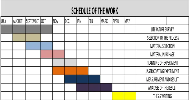
2.3 SCHEDULE OF WORK –
Fig 1: Schedule of work
JULY
AUGUST SEPTEMBER OCT
NOV
DEC
JAN
FEB
MARCH APRIL MAY
SELECTION OF THE PROCESS
THESIS WRITING
SCHEDULE OF THE WORK
LITERATURE SURVEY
MATERIAL SELECTION
MATERIAL PURCHASE
PLANNING OF EXPERIMENT
LASER COATING EXPERIMENT
MEASUREMENT AND RESULT
ANALYSIS OF THE RESULT
18 | P a g e
Chapter- 3
Experimental planning and procedure
:-
3.1 Experimental planning
The procedure can be divided into three stages:
1) Pre placing the powder
In this stage the coating material on which laser processing is to be done is sprayed over the base metal. Average precursor thickness will be 100-500 micro meter. Sprayed surfaces will be dried for 1hour prior to laser processing.
2) Laser Processing
In this stage laser will be used for laser processing operation. First the laser parameters such as laser power, scan speed etc. are properly set and Laser will be scanned over the pre placed powder surface which was obtained from the previous stage.
For our experiment the laser available is “Nd:YAG (neodymium-doped yttrium aluminum garnet; Nd:Y3Al5O12) is a crystal that is used as a lasing medium for solid-state lasers. The dopant, triply ionized neodymium, Nd(III), typically replaces a small fraction of the yttrium ions in the host crystal structure of the yttrium aluminium garnet (YAG), since the two ions are of similar size. It is the neodymium ion which proves the lasing activity in the crystal, in the same fashion as red chromium ion in ruby lasers. Generally the crystalline YAG host is doped with around 1% neodymium by atomic percent.
Nd:YAG lasers are optically pumped using a flashtube or laser diodes. These are one of the most common types of laser, and are used for many different applications. Nd:YAG lasers typically emit light with a wavelength of 1064 nm, in the infrared. Nd:YAG lasers operate in both pulsed and continuous mode. Pulsed Nd:YAG lasers are typically operated in the so called Q-switching mode: An optical switch is inserted in the laser cavity waiting for a maximum population inversion in the neodymium ions before it opens. Then the light wave can run through the cavity, depopulating the excited laser medium at maximum population inversion. In this Q-switched mode, output powers of 250 megawatts and pulse durations of
19 | P a g e
10 to 25 nanoseconds have been achieved. The high-intensity pulses may be efficiently frequency doubled to generate laser light at 532 nm, or higher harmonics at 355 and 266 nm.
Fig 2: Nd-YAG pulsed laser experimental setup for development of coating
Nd:YAG absorbs mostly in the bands between 730–760 nm and 790–820 nm. At low current densities krypton flash-lamps have higher output in those bands than do the more common xenon lamps, which produce more light at around 900 nm. The former are therefore more efficient for pumping Nd:YAG lasers.
The amount of the neodymium dopant in the material varies according to its use. For continuous wave output, the doping is significantly lower than for pulsed lasers. The lightly doped CW rods can be optically distinguished by being less colored, almost white, while higher-doped rods are pink-purplish.
20 | P a g e
Nd:YAG lasers are also used in manufacturing for engraving, etching, or marking a variety of metals and plastics. They are extensively used in manufacturing for cutting and welding steel, semiconductors and various alloys. For automotive applications (cutting and welding steel) the power levels are typically 1–5 kW. Super alloy drilling (for gas turbine parts) typically uses pulsed Nd:YAG lasers (millisecond pulses, not Q-switched). Nd:YAG lasers are also employed to make subsurface markings in transparent materials such as glass or acrylic glass. Lasers of up to 400 W are used for selective laser melting of metals in additive layered manufacturing. In aerospace applications, they can be used to drill cooling holes for enhanced air flow/heat exhaust efficiency. *”
The following are the laser parameters of the available ND:YAG laser used for the experimentation:-
Make – Alpha laser, Germany
Type – Nd-YAG laser
Wavelength – 1.06 micrometre
Max. Average power – 200 W
Pulse energy – 90 J
Peak pulse power – 10kW
Pulse duration – 0.5 to 20 ms
Pulse frequency – 20 Hz
Focus diameter – 0.2-2.2 mm
Max. Scan speed – 1500 mm/min
*
21 | P a g e
3.2
Experimental procedure
1) Pre placing the powder
Like discussed above, in this stage TiO2 , B4C powder mixed in alcohol or acetone is sprayed or painted on the base metal i.e. Aluminium. The powder precursor made of TiO2 , B4C suspended in alcohol or acetone is sprayed over the aluminium (base metal). Average precursor thickness will be 100-500 micro meter. Sprayed surfaces will be dried for 1hour prior to laser processing.
In present study, a pulsed Nd:Yag laser will be used to deposit TiO2 , B4C on the base metal (aluminium) which during coating process react to produce Al2O3;TiC;TiB2 on the base metal. The reaction would be as follows
(x+4)Al + 3TiO2 + B4C 2Al2O3 + Ti C + 2TiB2 + x Al
At 11000C or greater temperature and also the mole ratio of TiO2 and B4C should nearly
3:1 and by calculation the following is determined
TiO2 : B4C : Al 22.4 : 5.2 : 10 (weight ratio in accordance with the reaction)
For achieving a temperature that is higher than 11000C laser we use is capable of producing such high temperatures.
Now apart from the above reactive combination which is referred to as stoichiometric combination or Type-1 coating two other coatings are prepared i.e.
i) 7 parts stoichiometric combination + 3 parts aluminium powder (wt. ratio) or Type-2 coating
ii) 5 parts stoichiometric combination + 5 parts aluminium powder (wt. ratio) or Type-3 coating
2) Laser Processing
In this stage Nd:Yag pulsed laser will be used for laser coating operation. First the laser parameters such as laser power, scan speed etc. are properly set and Laser will be to scan over the pre placed powder surface which was prepared in the previous stage.
22 | P a g e
Fig 3: Schematic of laser coating process
Now in the laser processing different parameters are varied to find out the most effective and useful set among the test runs conducted. The parameters that can be varied has certain limitations due to the equipment available. Following are the laser parameters that are varied during the process:-
1. Peak power 2. Frequency
3. Ton (Pulse on time)
The above parameters affect the average power of the laser used. The relation between them is as follows
Average power = Frequency x Ton x Peak power
Where frequency is in pulse/sec
The following parameters were set on the laser equipment to carry out the coating process and the procedure was carried out in the order of stoichiometric mixture, then 7 parts stoichiometric mixture + 3 parts Al powder and finally 5 parts of stoichiometric mixture + 5 parts of Al powder
23 | P a g e
Table 2: Laser parameters used on corresponding samples with differently composed precursors
Sample No. Composition (weight ratio) Peak power (kw) Frequency (f)
Ton(ms) Pavg(w) Speed(mm/s) Speed in percentage 1 Stoichiometric 2 7 12 168 2.1 8.4 2 Stoichiometric 2.5 8 8 160 2.4 9.6 3 Stoichiometric 3 7 8 168 2.2 8.4 4 Stoichiometric 3.5 6 8 168 1.8 7.2 Overlap 0 Stoichiometric 3 8 168 2.2 8.4 5 7 parts stoichiometric mixture + 3 parts Al powder 2 7 12 168 2.1 8.4 6 -do- 2.5 8 8 160 2.4 9.6 7 -do- 3 7 8 168 2.2 8.4 8 -do- 3.5 6 8 168 1.8 7.2 Overlap 3 -do- 3 8 168 2.2 8.4 9 5 parts of stoichiometric mixture + 5 parts of Al powder 2 7 12 168 2.1 8.4 10 -do- 2.5 8 8 160 2.4 9.6 11 -do- 3 7 8 168 2.2 8.4 12 -do- 3.5 6 8 168 1.8 7.2 Overlap 4 -do- 3 8 168 2.2 8.4
In the above sample rum 1,2,3 and 4 represent the laser processing done over the stoichiometric combination under four different varied laser parametric conditions. The same varied laser parametric conditions were used over 5.6.7 and 8 sample runs which has 7 parts stoichiometric combination + 3 parts aluminium powder (wt. ratio) combination preplaced over aluminium and 9,10,11 and 12 sample runs which has 5 parts stoichiometric combination + 5 parts aluminium powder (wt. ratio) combination preplaced over aluminium.
In the above among the sample runs that were conducted, run no. 5,9and10, coating of the material on the aluminium did not occur due to low power usage.
Subsequently, different tests are carried out to find the type of coated surface formed on the base metal and its properties.
24 | P a g e
Fig 4: Sample of Type-1 coating material after laser treatment. (Tracks 1,2,3 and 4 from left to right)
Fig 5: Sample of Type-2 coating material after laser treatment. (Tracks 5,6,7 and 8 from left to right)
Fig 6: Sample of Type-3 coating material after laser treatment. (Tracks 11 and 12)
25 | P a g e
3) Measurement
Desired properties of the laser coated surface such as Hardness are measured using Vickers hardness test. Phase analysis will be done by XRD (X-ray diffraction technique). Microstructure of the coating laser affected zone of the substrate are studied using optical microscope.
For different tests we need the appropriate size of sample so in order to do that we cut the sample using Wire-EDM and hack-saw. The cut pieces of sample are then used for various required tests that need to be performed
Hardness testing:-
We cannot directly perform hardness test on the sample as it may damage the laser coating track on the aluminium samples. So in order to avoid the damage the sample piece is mounted and then polished enough to the surface to just let the sample track on to the testing.
After finely polishing the mounted samples, Vickers hardness test is performed on the available coated tracks of the samples after identifying their position. The following are the results of the hardness test performed.
26 | P a g e
Chapter 4
Results and discussion 4.1 Micro-hardness analysis
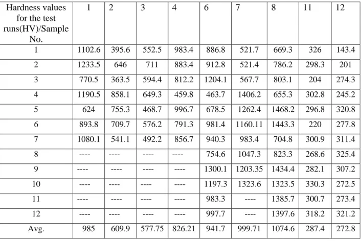
Micro hardness values obtained; all values in VHN units.
Table 3: Micro hardness test results
Hardness values for the test runs(HV)/Sample No. 1 2 3 4 6 7 8 11 12 1 1102.6 395.6 552.5 983.4 886.8 521.7 669.3 326 143.4 2 1233.5 646 711 883.4 912.8 521.4 786.2 298.3 201 3 770.5 363.5 594.4 812.2 1204.1 567.7 803.1 204 274.3 4 1190.5 858.1 649.3 459.8 463.7 1406.2 655.3 302.8 245.2 5 624 755.3 468.7 996.7 678.5 1262.4 1468.2 296.8 320.8 6 893.8 709.7 576.2 791.3 981.4 1160.11 1443.3 220 277.8 7 1080.1 541.1 492.2 856.7 940.3 983.4 704.8 300.9 311.4 8 ---- ---- ---- ---- 754.6 1047.3 823.3 268.6 325.4 9 ---- ---- ---- ---- 1300.1 1203.35 1434.4 282.1 307.2 10 ---- ---- ---- ---- 1197.3 1323.6 1323.5 330.3 272.5 11 ---- ---- ---- ---- 983.3 ---- 1385.7 300.7 273.4 12 ---- ---- ---- ---- 997.7 ---- 1397.6 318.2 321.2 Avg. 985 609.9 577.75 826.21 941.7 999.71 1074.6 287.4 272.8
Micro hardness test is carried out for all the samples available and the average of the obtained results in correspondence to the samples are tabulated in the above shown table. after this a graph is plotted with avg. micro-hardness against the sample no.
27 | P a g e
Graph 1: Micro-hardness vs Sample No. where hardness value ranges from 272.8 to 1074.6 VHN
From the above graphic results we can infer that excess aluminium presence in the preplaced combination does not help much in increasing the desired properties of the aluminium substrate by looking at the results of samples runs 9, 10, 11 and 12.
For stoichiometric combination we can see that at lower peak power of 2 Kw it shows
exceptionally high hardness and a fairly high hardness value is obtained for the higher 3.5 Kw peak power of laser.
As for the second type of combination that we tried, it is observed that with increase in the peak power the hardness of the coated samples also increased gradually reaching the highest value of 1074.6 VHN.
28 | P a g e
4.2
X-ray diffraction
:Fig 7: X-Ray Diffractometer
Following analysis can be done from XRD:
1) Phase determination- Identification of crystalline phases.
2) Phase analysis and Relative composition of mixed phases quantitatively.
3) Calculation of lattice parameters-Structural variations under different conditions.
4) Analysis of size and strain of the crystallite - Estimation of size of crystalline structure and disorder.
5) Structure solution and structure refinement of unknown crystal phases.
By using the data obtained from the XRD tests, 2θ values were plotted on the X-axis and the corresponding graph with peaks representing the available compounds in the sample was generated. The following figure shows the presence of different compounds in the
29 | P a g e
Fig 8/Graph 2: XRD pattern for coating processed with laser power 3 kW, frequency 7 Hz and scan speed 2.2 mm/s
In the above graph diffraction angles are on the X-axis and the corresponding peaks were marked in the format “2θ (corresponding compound representation)”. From the above figure we can see the formation of compounds like TiB2, TiC, Al2O3, TiB, Al3Ti on the Al
substrate which implies that the aim of coating TiB2, TiC on Al substrate through reaction is a
success.
4.3 Optical microscopy:
The optical microscope, also known commonly as the "light microscope", is a of microscope which uses visible light and a system of lenses to magnify images of small samples. Basic optical microscopes can be very simple, although there are many complex designs which are used to improve resolution and clear viewing of sample and contrast of sample.
30 | P a g e
Fig 9: Optical microscope
We use optical microscope to study the physical and structural formation of the laser treated samples i.e. how the laser affected the base aluminium during the laser coating process, depth and bonding characteristics of the laser coating tracks with the aluminium base as such. We can also study the width of the tracks at the microscopic level.
Optical micrograph at different resolutions can give us a wide scope to observe and study the samples in different ways. The following pictures were taken through optical microscope.
31 | P a g e
Fig 10: Base aluminium affected during the laser coating process of Type-2 coating at peak power of 3.5 Kw.
Fig 11: Base aluminium affected during the laser coating process of Type-3 coating at peak power of 3 Kw.
32 | P a g e
Fig 12: Base aluminium affected during the laser coating process of Type-3 coating at peak power of 3.5 Kw.
33 | P a g e
Chapter 5 CONCLUSION 5.1 Conclusion
TiC-TiB2 coating by reaction of TiO2 B4C and Al2O3, deposited on Al substrate by laser coating process using pulse Nd:YAG laser successfully. From the experimental result following conclusion can be drawn
1. For type 2 coating combination the micro-hardness depends upon the peak power of the laser in a proportional way.
2. For type 3 coating independent of the conditions used due to the high weight percentage of aluminium present in the coating material, it interferes with the laser coating process.
3. Type 1 coating does not follow any type of trend regarding the hardness value and corresponding laser parameters used.
34 | P a g e
REFERENCES:
X.B.Zhou, J.Th.M.De Hosson, A Reaction Coating on Aluminium Alloys by Laser Processing, Metallurgica et Materialia Vol. 28 (1993) pp. 219-224.
B.S. Yilbas, A. Matthews, A. Leyland, C. Karatas, S.S. Akhtar, B.J. Abdul Aleem, Laser surface modification treatment of aluminum bronze with B4C, Applied Surface Science 263 (2012) 804–809.
Jiang Xu, Wenjin Liu, Wear characteristic of in situ synthetic TiB2 particulate-reinforced Al matrix composite formed by laser cladding, Wear 260 (2006) 486–492. T.T. Wong, G.Y. Liang, C.Y. Tang, The surface character and substructure of aluminium laser-melting treatment, Journal of Materials Processing Technology 66 (1997) 172- 178.
U. Wendt, S. Settegast, I.U.Grodrion, Laser alloying of aluminum with titanium wire, JOURNAL OF MATERIALS SCIENCE LETTERS 22(2003), 1319 – 1322.
F. Vollertsen,K. Partes,G. Habedank,T. Seefeld, Deep penetration dispersing of
aluminum with TiB2 using a single mode fiber laser, Prod. Eng. Res. Devel. (2008) 2:27– 32.
Keisuke Uenishi, Kojiro F. Kobayashi, Formation of surface layer based on Al3Ti on aluminum by laser cladding and its compatibility with ceramics, Intermetallics 7 (1999) 553-559.
J. Senthil Selvan, G. Soundararajan, K. Subramanian, Laser alloying of aluminium with electrodeposited nickel: optimisation of plating thickness and processing parameters, Surface and Coatings Technology 124 (2000) 117–127.
H.C. Man, S. Zhang, F.T. Cheng, Improving the wear resistance of AA 6061 by laser surface alloying with NiTi, Materials Letters 61 (2007) 4058–4061.
Lalitha R. Katipelli, Arvind Agarwal, Narendra B. Dahotre, Interfacial strength of laser surface engineered TiC coating on 6061 Al using four-point bend test, Materials Science and Engineering A289 (2000) 34–40.
Puja Kadolkar, Narendra B. Dahotre, Effect of processing parameters on the cohesive strength of laser surface engineered ceramic coatings on aluminum alloys, Materials Science and Engineering A342 (2003) 183-191.
J. Dutta Majumdar, B. Ramesh Chandra, A.K. Nath, I. Manna, Compositionally graded SiC dispersed metal matrix composite coating on Al by laser surface engineering, Materials Science and Engineering A 433 (2006) 241–250.
35 | P a g e
L. Dubourg, D. Ursescu, F. Hlawk, A. Cornet, Laser cladding of MMC coatings on aluminium substrate: influence of composition and microstructure on mechanical properties, Wear 258 (2005) 1745–1754.
D. K. Das, Surface roughness created by laser surface alloying of aluminium with nickel, Surface and Coatings Technology, 64 (1994) 11-15.
P.H. Chong, H.C. Man, T.M Yue, Microstructure and wear properties of laser surface-cladded Mo-WC MMC on AA6061 aluminium alloy, Surface and Coatings Technology 145 (2001), 51-59.
T. M. Yue, K. J. Huang, H. C. Man, Formation of amorphous Al2O3 phase on aluminum alloy by in-situ laser cladding, JOURNAL OF MATERIALS SCIENCE 39 (2004) 6599 – 6602.
M.H. Staia , M. Cruz, N.B. Dahotre, Wear resistance of a laser alloyed A-356 aluminum/WC composite, Wear 251 (2001) 1459–1468.
S. Tomida, K. Nakata, S. Saji, T. Kubo, Formation of metal matrix composite layer on aluminium alloy with TiC-Cu powder by laser surface alloying process, Surface and Coatings Technology 142(2001) 585-589.
Subhasisa Nath, Sisa Pityana, Jyotsna Dutta Majumdar, Laser surface alloying of aluminium with WC+Co+NiCr for improved wear resistance, Surface & Coatings Technology 206 (2012) 3333–3341.
G.Y. Liang, J.Y. Su, The microstructure and tribological characteristics of laser-clad Ni–Cr–Al coatings on aluminium alloy, Materials Science and Engineering A290 (2000) 207–212.
S. Nayak, Hsin Wang, Edward A. Kenik, Ian M. Andersond, Narendra B. Dahotre, Observation of exothermic reaction during laser-assisted iron oxide coating on aluminum alloy, Materials Science and Engineering A 390 (2005) 404–413.