Analysis of Combined Impact Wear and Abrasion in Hard Coating Welds
(FeCrMo) (GMAW and GMAW-CW)
Catiane Monteiro Lima, catianemonteiro@yahoo.com.br¹ Any Suelem Andrade Ferreira, anyferreira06@gmail.com² Alberto Ribeiro Corrêa, albertonature@hotmail.com² Eduardo de Magalhães Braga, edbraga@ufpa.br² Victor Oliveira Ferreira, victorf9@hotmail.com³
1Universidade Federal do Pará, Departamento de Engenharia Mecânica/LCAM, Belém, Pará, Brasil 2Universidade Federal do Pará, Departamento de Engenharia Mecânica/LCAM, Belém, Pará, Brasil ³Universidade Federal do Pará, Departamento de Engenharia Química, Belém, Pará, Brasil
Abstract. The Brazilian mineral production has an important influence in the national economy consequently it is always searching for improvements in the sector. This work is a study of the deposited coatings resistance by Gas Metal Arc Welding (GMAW) and Gas Metal Arc Welding - Cold Wire (GMAW -CW) processes with use of low- alloy CrNiMo wires. And aims to test new alloys to be applied in the semi- autogenous mill liners – SAG recovery. Thus coatings were tested with different amounts of cold wire addition (0, 10, 20 and 30%) that were subsequently tested in impact and abrasion tester combined (ITAC ) to evaluate their mass loss suffered under the same conditions and testing time. Microstructural and mechanical properties analysis of each coating sample were done to verify what coat had the better behave under the combined impact and abrasion conditions and better response to resist wear conditions. The results showed that the coating with 30 % of cold wire showed lower weight loss when compared to the other, indicating its better resistance under the test conditions.
Keywords: Coats, GMAW, GMAW-CW, ITAC.
1. INTRODUCTION
The semi- autogenous grinding (SAG) is the step where material suffers comminution in a rotary mill with feed material, plus an additional means of grinding. In this type of grinding is used a small amount of steel balls, 3 - 20% of the mill volume is added to the mill to facilitate fragmentation of a tougher grinding fraction which tends to remain a long time in the mill or return sorter as current load.
The ore movement and the grinding media together during the milling process submit the coating mills to impact and abrasion conditions, which reduces the coating life and increase the need for maintenance. Thus, we developed different types of coating welds by GMAW and GMAW -CW processes which were submitted to the Impact Test and Abrasion Combined in specific equipment for this type test.
2. BACKGROUND AND THEORETICAL CONCEPTS
At first, the coating of a mill was meant only to serve as a protection against wear, but over the years different coating systems mill passed through many stages of development.
A few decades ago, the concept of using the coating is intended to not only protect the cylinder against wear, but also reduce the slip Grinder load inside the housing and to provide appropriate paths [1].
According to Luz et al [2], the coatings are made of different metal alloys, rubber and rarely ceramic or quartzite for very special uses. Various forms of coatings are produced, in the type of mill (balls or bars) including size, material processing, operating speed, etc.
Steel coatings represent the majority of coating materials used in the world, taking into account the current consumption. It appears that the steel is successfully used either in dry applications, or wet to be a very versatile material.
Oliveira apud Bergeman [3] reports that usually the metal- semi- autogenous mills is produced with low alloy steels containing chromium (Cr) and molybdenum (Mo) (chrome moly steels). He also reports that the Cr -Mo type steels have good resistance to impact and abrasion.
The information about coating cited by Bergerman served as the basis for the development of this research as regards the pursuit of new alloys for applications in semi- autogenous mill liners.
2.1. Hard Coatings Resistant Wear
The main characteristic of this type of coating is its high hardness produced by welding application of a hard and wear-resistant layer on the workpiece surface subjected to this phenomenon and can be applied to new parts, and recovery by use of worn parts.
Ferrous materials low-alloy
1A 2 a 6 1B 6 a 12
Cr, Mo, Mn Cr, Mo, Mn
Ferrous materials high alloyed
2A 12 a 15 2B 12 a 25 2C 12 a 25 2D 30 a 37 3A 25 a 50 3B 25 a 50 3C 25 a 50 Cr, Mo Mo, Cr Mn, Ni Mn, Cr, Ni Cr, Ni, Mo Cr, Mo Co, Cr
Nickel based alloys and cobalt based
4A 50 a 100 4B 50 a 100 4C 50 a 100 Co, Cr, W Ni, Cr, Mo Cr, Ni, Mo carbides
5 75 a 96 WC WC or in combination with other
carbides such as TiC and TaC , always in a metal matrix
2.2. Coating Welding
The welding coating consists of depositing a welding consumable more noble than metal base, aimed at specific applications such as higher hardness, wear resistance or corrosion protection of the base metal which is not resistant as the material of the coating.
Direct deposition of metal coating weld on the base metal is only possible when the two metals are diluted other. This is the case, for example, the deposition of any carbon steel on stainless steel or alloy steels. When the two metals are not diluted, the problem can be solved by deposition of an intermediate layer of a third metal which is compatible with both.
The weld deposition may be done by submerged arc welding (with wire or tape electrode) or by welding with protective inert gas (MIG, for example) or by projection with plasma.
Depending on the process, the coating thickness can range from 4 to 7 mm, the penetration in the base metal 1 to 1.5 mm and dilution from 10 to 20%.
2.3. Welding Processes
The MIG / MAG or GMAW (Gas Metal Arc Welding ) welding process arc is based on the formation of an electric arc between the workpiece and a massive naked electrode consumable with continuous feed. The protection of the arc and the weld region from contamination by the atmosphere is made by a gas or gas mixture supplied with adequate pressure and flow rate, Fig. 1a.
Studies of GMAW welding with additional cold wire (not energized), called GMAW -CW (Gas Metal Arc Welding- Cold Wire), has emerged as a variant of the GMAW welding process double wire. Since the beginning of its development (2005), the Welding Laboratory of UFPA, has been studying the operational feasibility, economic and metallurgical welding with addition of cold wire for welding coating and filling bevels.
The proposal of GMAW-CW welding is to be a technical and economic alternative to conventional GMAW welding. This new version uses only a conventional (constant voltage source) with an extra head for feeding cold wire connected to welding torch [4] as can be seen in Fig. 1b compared with GMAW in Fig. 1a .
(a) (b)
Figure 1: Schematic drawing of GMAW processes (a) and GMAW -CW (b).
2.4. Impact Test and Abrasion Combined (ITAC)
In many fields of industry, the abrasion and erosion processes are dominant in equipment and these mechanisms reduce the service life of expensive machines. Resistance to abrasion and / or impact, and the ability to withstand other complex mechanical actions are often necessary.
In order to quantify specific material properties such as resistance mechanisms, various test methods are in use. Wilson and Hawk [5], reported an abrasion test that was developed in the Albany Research Center (ARC). This test is a modification of the initial design bond, the bond test uses just one test sample and ARC uses three, allowing more possibilities for analysis.
As the name implies, the purpose of this machine is to simulate the wear that occurs by two mechanisms, impact and abrasion which occur in the samples used in the assay. Both the ASTM G65 and ASTM B611 has the disadvantage that they do not simulate impact tool wear.
The test, Fig. 2, consists of a rotating wheel with three blades that sample are located on a rotating drum. The drum and the wheel turn in the counterclockwise direction during the tests at approximately 45 and 620 rpm respectively. Before you start, the cylinder is filled with 0.6 kg of abrasive material that interacts with the samples during testing. The drum is coated with rubber to allow elevation of the abrasive material until gravity overcomes the friction forces to occur and the coating material drops on the blades. Another advantage with the rubber lining is the reduction of noise during rehearsals.
Figure 2: Schematic drawing of an impact test developed by abrasion ARC
.
The Metallic Materials Characterization Laboratory (LCAM) used a device that uses the same operating principles of the equipment developed by ARC, aiming to simulate in the laboratory the conditions of impact and abrasion that the SAG mill liners are subjected when in service.
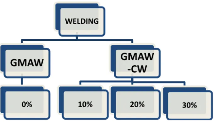
Figure 3: Flowchart diagram welding.
Welds were made in the flat position, in five passes with reverse polarity in a welding bench, as illustrated in the Fig. 4.
Figure 4: Welding workbench layout. Welding torch 1, cold wire nozzle 2, linear displacement device 3, support for attachment of the specimens 4.
b) Metallography
After the removal of a sample of each specimen, they were sanded with wet- in particle sizes ranging from 36 to 800μm, and polishing was carried out with polishing cloth, diamond paste with a particle size of 3μm and metallographic lubricant. The test pieces were ground in wet- in grit sizes from 36 to 60 μm so that they obtain a flat surface for subsequent testing in ITAC.
c) Microstructural Analysis
To reveal the microstructure resulting from the welding process was used Villela 's reagent (5 mL HCl, 1 g of picric acid , 100 ml ethyl alcohol) attack by immersion 10s ( ± 2s) depending on the cold-wire ratio. The disclosed microstructures were visualized by light microscopy in increments of 50, 100, 200, 500 and 1000 times.
d) Microhardness Analysis
The hardness was obtained using a durometer microvickers with 0.01 gf load and speed of 10 microns / s. The indentations were performed on three lines with a distance of 0.5 mm between each point, totaling 30 indentations per sample.
e) Impact Test and Abrasion Combined (ITAC)
To carry out the wear test were used 2.4 kg of dry crushed and sieved, bystanders in 12.4 mm sieve and retained on the 9.4 mm. This amount was divided into four parts each 600g, Fig. 5.
The choice of abrasive was due its natural features, it has an irregular geometric shape, with many sharp edges in their units.
WELDING
GMAW
0%GMAW
-CW
10% 20% 30%Figure 5: Brita, vibrating screen and digital scale used.
.
The test was conducted in WAT in 1 hour, which is divided into four times of 15min. To each test of 15min were used 600g of crushed stone at the end of each quarter hour of the equipment stopped running , the gravel was removed completely, the pieces were washed , weighed in the balance and subsequently placed back into the machine for performing a new test cycle with other 600g of crushed stone. This cycle was repeated until the end of the one hour test.
(a) (b)
Figure 6: Provision of equipment used for testing. TIAC and the control panel ( a) , enlarged image TIAC barrel ( b ).
4. Results
a) Microstructure result
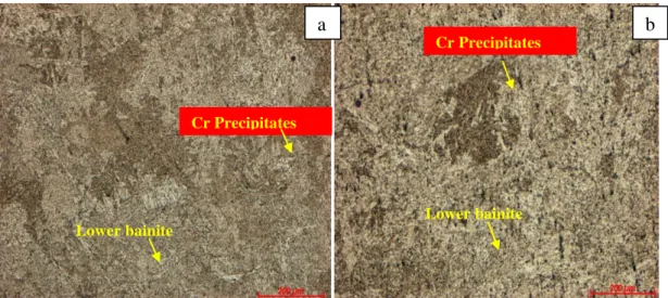
The samples analyzed for different rates of cold wire addition had similar results with regard to the microstructure present in the welded cladding, differing from each other by quantitative phases present in these microstructures gradually increased with the addition of cold wire, Fig 7 and Fig.8. It is possible to see the Lower bainite (light phase) with chromium precipitation (dark phase).
Figure 7: Microstructure of the sample without addition of AF. Magnification 100x and attack by immersion 12s in Vilella (a) and Microstructure of the sample with 10% addition of AF. 100x magnification and attack by immersion in
Vilella 10s (b) .
Figure 8: Microstructure of the sample with 20% addition of AF. Magnification 100x and attack by immersion in Vilella 7s (a) and Microstructure of the sample with 30% addition of AF. 100x magnification and attack by immersion
in Vilella 5s (b).
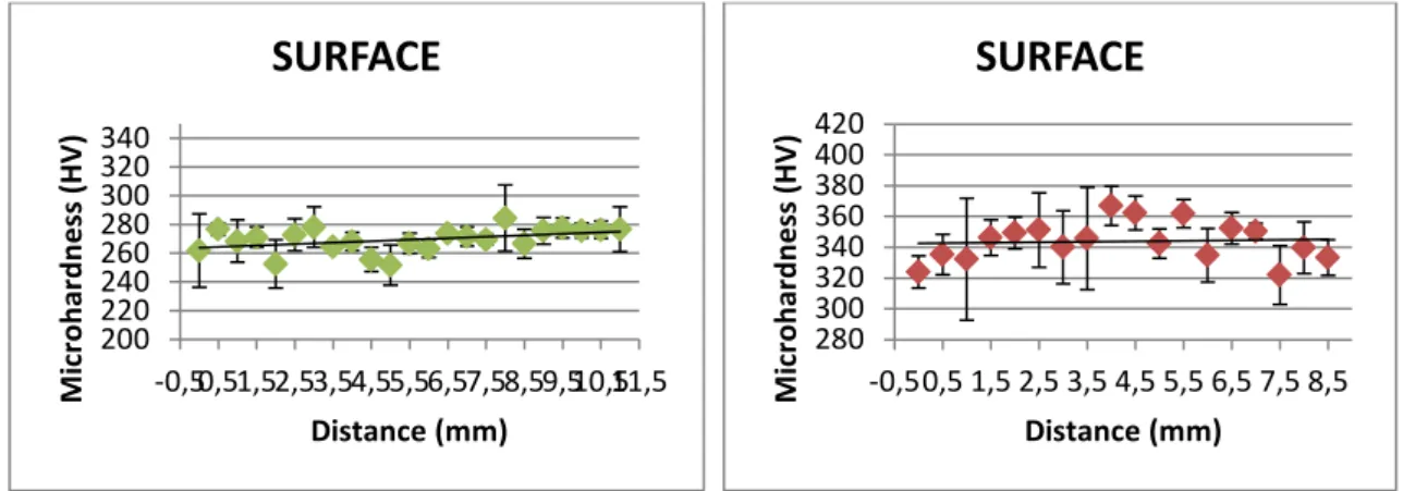
b) Microhardness result
The hardness results obtained for each sample are consistent with the expected, since the hardness gradually increased with increasing cold wire content, Fig. 9, jumping from an initial hardness of 240HV on average for welding condition without addition of cold wire to a final average hardness of 340HV for the welding condition added with 30% of cold wire. 160 180 200 220 240 260 280 300 -0,50,51,52,53,54,55,56,57,58,59,510,5 M ic ro h ar d n e ss (H V) Distance (mm)
SURFACE
230 280 330 -0,5 1 2,5 4 5,5 7 8,5 1011,513 M ic ro h ar d n e ss(HV
)
Distance(mm)SURFACE
a
b
Lower bainite Lower bainite Lower bainite Lower bainite Cr Precipitates Cr PrecipitatesFigure 9: Microhardness results for the specimens with 0, 10, 20 e30 % added cold wire. c) ITAC test result
The specimen tested under the same conditions of impact and abrasion in ITAC presented different results in relation to wear, as can be seen in the charts below in which it has a mass loss ratio as a function of test time can be seen that tested specimen resist more to wear when you have a higher content of cold wire, Fig. 10. This information can also be confirmed by the data provided in Tab. 2.
Figure 10: Cumulative weight loss vs. time for specimen without the addition of PA and the specimen 10, 20 and 30% addition of cold wire.
Table 2: Initial weight of specimen and after every 15 minutes interval, and total mass loss at the end of the test.
200 220 240 260 280 300 320 340 -0,50,51,52,53,54,55,56,57,58,59,510,511,5 M ic ro h ar d n e ss (H V) Distance (mm)
SURFACE
280 300 320 340 360 380 400 420 -0,50,5 1,5 2,5 3,5 4,5 5,5 6,5 7,5 8,5 M ic ro h ar d n e ss (H V) Distance (mm)SURFACE
473 473,1 473,2 473,3 473,4 473,5 473,6 0 50 100 Wei gh t Ch an ge ( g) Time (min) Desgaste 0% 478,2 478,3 478,4 478,5 478,6 478,7 478,8 0 50 100 Wei gh t Ch an ge ( g) Time (min) Desgaste 10% 503,6 503,7 503,8 503,9 504 504,1 504,2 0 50 100 Wei gh t Ch an ge ( g) Time (min) Desgaste 20% 479,35 479,4 479,45 479,5 479,55 0 50 100 Wei gh t Ch an ge ( g) Time (min) Desgaste 30% Test Time 1 hourWeight of initial CP and after every 15 minutes interval (g) 0% 10% 20% 30% 0 min. 473,5 478,7 504,1 479,5 15 min. 473,4 478,6 504,0 479,4 30 min. 473,2 478,4 503,8 479,4 45 min. 473,1 478,3 503,7 479,4 60 min. 473,1 478,3 503,7 479,4
microstructure.
Regarding the behavior of different specimens during the ITAC test, the results presented in Tab. 2 show us the best specimen resistance with 30% cold wire addition, that lost less weight during the test, which indicates the improved resistance provided by cold wire to combined impact and abrasion conditions.
6. Conclusions
The welded coatings obtained by GMAW with 20% and 30% cold wire addition did not show coarse lower bainite as observed for GMAW and GMAW-CW with 10% cold wire addition.
It was observed in all GMAW-CW welded coatings analysis the presence of dark regions that can be accumulation of Cr inclusions.
The microhardness found in the GMAW samples coatings was lower when compared to the GMAW-CW samples coatings microhardness. The microhardness increased with cold wire percentage increase, so it can be conclude that for the analyzed situation the addition of a cold-wire with a higher content of alloying elements, especially Cr, pushed up the hardness of the coatings.
The coatings mass loss observed during tests in ITAC implies that the cold wire percentage addition in GMAW-CW process offered improved wear resistance compared GMAW process under the same test conditions.
It was observed in the mass loss versus time graphic that the 30% cold wire addition provided a wear stability in the tested conditions.
7. References
[1] VALADÃO, G.E.; ARAUJO, A.C. – Introdução ao Tratamento de Minérios. Belo Horizonte: Editora UFMG. 2007, 234p.
[2] LUZ, A. B., SAMPAIO, J. A., e FRANÇA, S. C. A. - Tratamento de Minérios - Centro de Tecnologia Mineral – CETEM, Ministério da Ciência e Tecnologia – MCT- Rio de Janeiro. 5 ed. 2010, 963 pg
[3] BERGEMAN, M., G. – Modelagem e Simulação do Circuito de Moagem Sossego – Dissertação apresentada a Escola Politécnica da Universidade de São Paulo. 2009, 208pg.
[4] SÁBIO, A. D. Estudo da Viabilidade Operacional do Processo de Soldagem MAG com Alimentação Adicional de Arame Frio. 2007. 147p. Dissertação (Mestrado em Engenharia Mêcanica) - Universidade Federal do Pará, Belém. 2007.