Disclosure to Promote the Right To Information
Whereas the Parliament of India has set out to provide a practical regime of right to
information for citizens to secure access to information under the control of public authorities,
in order to promote transparency and accountability in the working of every public authority,
and whereas the attached publication of the Bureau of Indian Standards is of particular interest
to the public, particularly disadvantaged communities and those engaged in the pursuit of
education and knowledge, the attached public safety standard is made available to promote the
timely dissemination of this information in an accurate manner to the public.
इंटरनेट
मानक
“
!ान $ एक न' भारत का +नम-ण
”
Satyanarayan Gangaram Pitroda “Invent a New India Using Knowledge”
“प0रा1 को छोड न' 5 तरफ”
Jawaharlal Nehru“Step Out From the Old to the New”
“जान1
का
अ+धकार
,
जी1
का
अ+धकार”
Mazdoor Kisan Shakti Sangathan“The Right to Information, The Right to Live”
“
!ान एक ऐसा खजाना > जो कभी च0राया नहB जा सकता है
”
Bhartṛhari—Nītiśatakam“Knowledge is such a treasure which cannot be stolen” “Invent a New India Using Knowledge”
ह
ै
”
ह
”
ह
IS 13935 (2009): Seismic Evaluation, Repair and
Strengthening of Masonry Buildings - Guidelines [CED 39: Earthquake Engineering]
© BIS 2009
B U R E A U O F I N D I A N S T A N D A R D S
M A N A K B H A V A N , 9 B A H A D U R S H A H Z A F A R M A R GNEW DELHI 110002
Hkkjrh; ekud
fpukbZ okys Hkouksa ds Hkwdaih; ewY;kadu ejEer vkSj
lqn``<+hdj.k
—
ekxZnf'kZdk
(
igyk iqujh{k.k
)
Indian Standard
SEISMIC EVALUATION, REPAIR AND STRENGTHENING
OF MASONRY BUILDINGS — GUIDELINES
( First Revision )
FOREWORD
This Indian Standard (First Revision) was adopted by the Bureau of Indian Standards, after the draft finalized by the Earthquake Engineering Sectional Committee had been approved by the Civil Engineering Division Council. Himalayan-Naga Lushai region, Indo-Gangetic Plain, Western India and Kutch and Kathiawar regions are geologically unstable parts of the country and some devastating earthquakes of the world have occurred there. A major part of the peninsular India has also been visited by moderate earthquake, but these were relatively few in number and had considerably lesser intensity. It has been a long felt need to rationalize the earthquake resistant design and construction of structures taking into account seismic data from studies of the Indian earthquakes, particularly in view of the heavy construction programme all over the country. It is to serve this purpose that IS 1893 : 1962 ‘Criteria for earthquake resistant design of structures’ was formulated and subsequently revised in 1966, 1970, 1975, 1984 and 2002. It lays down the seismic zones, the basic seismic coefficients and other factors and criteria for various structures. As an adjunct to IS 1893, IS 4326 ‘Code of practice for earthquake resistant design and construction of buildings’ was formulated in 1967 and revised in 1976 and in 1993. The 1976 version contained some recommendations for low strength brick masonry and stone buildings which have now been covered in greater detail in IS 13828 : 1993 ‘Guidelines for improving earthquake resistance of low strength masonry building’.
Earthquake damages to buildings in Himachal Pradesh, North Bihar and hill districts of Uttar Pradesh emphasized the need to formulate this standard to cover guidelines for repair and strengthening of these buildings from any future earthquakes and it was first published in 1993.
The following are the major important modifications made in this revision:
a) Non-shrink grouts and fiber reinforced plastics have been incorporated for repair, restoration work and strengthening.
b) Damageability assessment of existing masonry buildings under earthquake occurrences has been incorporated.
c) Assessment of retrofitting requirements and actions for retrofitting also incorporated. d) Provision of seismic belts around door and window openings.
e) Rapid visual screening method along with RVS survey forms for masonry buildings for seismic hazards evaluation has been incorporated.
In this revision, due weightage has been given to international coordination among standards and practices prevailing in different countries in the field in the country.
For the purpose of deciding whether a particular requirement of this standard is complied with, the final value observed or calculated, expressing the result of a test or analysis, shall be rounded off in accordance with IS 2 : 1960 ‘Rules for rounding off numerical values (revised)’. The number of significant places retained in the rounded off value should be the same as that of specified value in this standard.
Indian Standard
SEISMIC EVALUATION, REPAIR AND STRENGTHENING
OF MASONRY BUILDINGS — GUIDELINES
( First Revision )
1 SCOPE
1.1 This standard covers the selection of materials and
techniques to be used for repair and seismic strengthening of damaged buildings during earthquakes. It also covers the dama geability assessment and retrofitting for upgrading of seismic resistance of existing masonry buildings covered under IS 4326 and IS 13828.
1.2 The repair materials and techniques described
herein may be used for all type of masonry buildings and construction.
1.3 The provisions of this standard are applicable for
buildings in seismic Zones III to V of IS 1893 (Part 1). These are based on damaging seismic intensities VII and more on M. S. K. Intensity scales. The scheme of strengthening should satisfy the requirements stipulated for the seismic zone of IS 1893 (Part 1), building categories of IS 4326 and provisions made in this Code and in IS 13828 for low strength masonry building. No special seismic resistance features are considered necessary for buildings in seismic Zone II, but the important buildings in this Zone may also be considered for upgrading their seismic resistance.
1.4 The suggested reinforcing of horizontal and vertical
seismic belts in this standard follows IS 4326 requirements of horizontal seismic bands and vertical bars at critical sections. For special buildings having larger span and heights beyond the dimensions considered in IS 4326 and in this standard, special analysis may be carried out at the responsibility of the specialist.
2 REFERENCES
The standards given below contain provisions which through reference in this text, constitute provisions of this standard. At the time of publication, the editions indicated were valid. All standards are subject to revision, and parties to agreements based on this standard are encouraged to investigate the possibility of applying the most recent editions of the standards given below:
IS No. Title
1893 (Part 1) : Criteria for earthquake design of 2002 structures: Part 1 General Provisions
and buildings
4326 : 1993 Code of practice for earthquake resistant design and construction of buildings (third revision)
13828 : 1993 Guidelines for improving earthquake resistance of low strength masonry buildings
3 TERMINOLOGY
For the purpose of this Code, the definitions given in IS 1893 (Part 1) and the following shall apply.
3.1 Box System — A bearing wall structure without a
space frame, the horizontal forces being resisted by the walls acting as shear walls.
3.2 Centre of Rigidity — The point in a structure,
where a lateral force shall be applied to produce equal deflections of its components, at any one level in any particular direction.
3.3 Design Seismic Coefficients — The value of
horizontal seismic coefficient computed taking into account the zone factor, soil system, the importance factor and the response reduction factor as specified in IS 1893 (Part 1).
3.4 Seismic Band — A reinforced concrete, reinforced
brick or wooden runner provided horizontally in the walls to tie them together and to impart horizontal bending strength in them.
3.5 Seismic Belt — A cast-in-place Ferro-cement
plating installed post-construction on the masonry wall in lieu of the seismic bands or vertical reinforcing bars specified in IS 4326 and IS 13828.
3.6 Seismic Zone and Seismic Coefficient —
Classification of seismic Zones II to V and the corresponding basic seismic coefficients shall be as specified in IS 1893 (Part 1).
force in its own plane. Braced frames, subjected primarily to axial stresses, shall be considered as shear walls for the purpose of this definition.
4 GENERAL PRINCIPLES AND CONCEPTS 4.1 Non-structural/Architectural Repairs
4.1.1 The buildings affected by earthquake may suffer
both non-structural and structural damages. Non-structural repairs may cover the damages to civil and electrical items including the services in the building. Repairs to non-structural components need to be taken up after the structural repairs and retrofitting work are carried out. Care should be taken about the connection details of architectural components to the main structural components to ensure their stability.
4.1.2 Non-structural and architectural components get
easily affected/dislocated during the earthquake. These repairs involve one or more of the following:
a) Patching up of defects such as cracks and fall of plaster;
b) Repairing doors, windows, replacement of glass panes;
c) Checking and repairing electric conduits/ wiring;
d) Checking and repairing gas pipes, water pipes and plumbing services;
e) Re-building non-structural walls, smoke chimneys, parapet walls, etc;
f) Replastering of walls as required; g) Rearranging disturbed roofing tiles;
h) Relaying cracked flooring at ground level; and j) Redecoration — white washing, painting, etc. The architectural repairs as stated above do not restore the original structural strength of structural components in the building and any attempt to carry out only repairs to architectural/non-structural elements neglecting the required structural repairs may have serious implications on the safety of the building. The damage would be more severe in the event of the building being shaken by the similar shock because original energy absorption capacity of the building would have been reduced.
4.2 Structural Repairs/Restoration
4.2.1 Prior to taking up of the structural repairs for
restoration of original strength and any strengthening measures, it is necessary to conduct detailed damage assessment to determine:
a) the structural condition of the building to decide whether a structure is amendable for repair; whether continued occupation is
permitted; to decide the structure as a whole or a part require demolition, if considered dangerous;
b) if the structure is considered amendable for structural repair then detailed damage assessment of the individual structural components (mapping of the crack pattern, distress location; crushed concrete, reinforcement bending/yielding, etc). Non-destructive testing techniques could be employed if found necessary, to determine the residual strength of the members; and c) to work out the details of temporary
supporting arrangement of the distressed members so that they do not undergo further distress due to gravity loads.
4.2.2 After the assessment of the damage of individual
structural elements, appropriate repair methods are to be carried out component wise depending upon the extent of damage. The restoration work may consist of the following:
a) Removal of portions of cracked masonry walls and piers and rebuilding them in richer mortar. Use of non-shrinking mortar will be preferable.
b) Addition of reinforcing mesh on both faces of the cracked wall, holding it to the wall through spikes or bolts and then covering it, suitably, with micro-concrete (maximum size of aggregate limited to 6 mm or less as suitable), and may be with use of micro-reinforcement as fibre or ferro-cement. c) Injecting cement, polymer-cement mixture or
epoxy materials which are strong in tension, into the cracks in walls.
d) The cracked reinforced concrete elements like slabs, beams and lintels may be repaired by epoxy grouting and could be strengthened by epoxy or polymer mortar application like shotcreting, jacketing, etc.
NOTE — In mortar for masonry or plaster, fibers can be used.
4.3 Seismic Strengthening
The main purpose of the seismic strengthening is to upgrade the seismic resistance of a damaged building while repairing so that it becomes safer under future earthquake occurrences. This work may involve some of the following actions:
a) Increasing the lateral strength in one or both directions by increasing column and wall areas or the number of walls and columns. b) Giving unity to the structure, by providing a
proper connection between its resisting elements, in such a way that inertia forces generated by the vibration of the building can be transmitted to the members that have the ability to resist them. Typical important aspects are the connections between roofs or floors and walls, between intersecting walls and between walls and foundations.
c) Eliminating features that are sources of weakness or that produce concentration of stresses in some members. Asymmetrical plan distribution of resisting members, abrupt changes of stiffness from one floor to the other, concentration of large masses and large openings in walls without a proper peripheral reinforcement are examples of defects of this kind.
d) Avoiding the possibility of brittle modes of failure by proper reinforcement and connection of resisting members.
4.4 Seismic Retrofitting
Many existing buildings do not meet the seismic strength requirements of present earthquake codes due to original structural inadequacies and material degradation over time or alterations carried out during use over the years. Their earthquake resistance can be upgraded to the level of the present day codes by appropriate seismic retrofitting techniques, such as mentioned about seismic strengthening in 4.3.
4.5 Strengthening or Retrofitting Versus Reconstruction
4.5.1 Replacement of damaged buildings or existing
unsafe buildings by reconstruction is, generally, avoided due to a number of reasons, the main ones among them being:
a) Higher cost of re-building than that of strengthening or retrofitting,
b) Preservation of historical architecture, and c) Maintaining functional social and cultural
environment.
In most instances, however, the relative cost of retrofitting to reconstruction cost determines the decision. As a thumb rule, if the cost of repair and seismic strengthening is less than about 30 percent of the reconstruction cost, the retrofitting is adopted. This may also require less working time and much less dislocation in the living style of the population. On the other hand reconstruction may offer the possibility of modernization of the habitat and may be preferred by well-to-do communities.
4.5.2 Cost wise the building construction including the
seismic code provisions in the first instance, works out the cheaper in terms of its own safety and that of the occupants. Retrofitting an existing inadequate building may involve as much as 2.5 to 3 times the initial extra expenditure required on seismic resisting features. Repair and seismic strengthening of a damaged building may even be 4 to 6 times as expensive. It is therefore very much safe as well as cost-effective to construct earthquake resistant buildings at the initial stage itself according to the relevant seismic Indian Standards.
5 SELECTION OF MATERIALS AND TECHNIQUES
5.1 General
The most common materials for repair, restoration works of various types of buildings are cement and steel. In many situations suitable admixture may be added to cement mortar/cement concrete to improve their properties, such as, non-Shrinkage, bond, etc. Steel may be required in many forms like bolts, rods, angles, beams, channels, expanded metal and welded wire fabric. Wood and bamboo are the most common material for providing temporary supports and scaffolding, etc, and will be required in the form of rounds, sleepers, planks, etc.
Besides the above, special materials and techniques are available for best results in the repair and strengthening operations. These should be selected appropriately depending on the nature and cost of the building that is to be repaired, materials availability and feasibility, and use of available skills, etc. Some special materials and techniques are described below.
5.2 Non-shrink Grouts
Currently ready grout contents consisting of a polymer, non-shrink cement and special sands are available in the market which is suitable to prepare the desired grout for the crack width observed in the masonry. The polymer improves the adhesion of the grout with the masonry as well imparts higher tensile strength.
5.3 Shotcrete
Shotcrete is cement mortar or cement concrete (with coarse aggregate size maximum 10 mm) conveyed through a hose and pneumatically placed under high velocity on to a prepared concrete or masonry surface. The force of the jet impingement on the surface, compacts the shotcrete material and produces a dense homogeneous mass. Basically there are two methods of shotcreting; wet mix process and dry mix process. In the wet mix process, all the ingredients, including water are mixed together before they enter the delivery hose. In the dry mix process, the mixture of damp sand
and cement is passed through the delivery hose to the nozzle where the water is added. The dry mix process is generally used in the repair of concrete elements. The bond between the prepared concrete surface of the damaged member and the layer of shotcrete is ensured with the application of suitable epoxy adhesive formulation. The shear transfer between the existing and new layer of concrete is ensured with the provision of shear keys. Addition of fibers enhances tensile strength and toughness.
5.4 Epoxy Resins
Epoxy resins are excellent binding agents with high tensile strength. These are chemical preparations the compositions of which can be changed as per requirements. The epoxy components are mixed just prior to application. Some products are of low viscosity and can be injected in fine cracks too. The higher viscosity epoxy resin can be used for surface coating or filling larger cracks or holes. The epoxy resins may also be used for gluing steel plates to the distressed members.
5.5 Epoxy Mortar
For larger void spaces, it is possible to combine the epoxy resins of either low viscosity or higher viscosity with sand aggregate to form epoxy mortar. Epoxy mortar mixture has higher compressive strength, higher tensile strength and a lower modulus of elasticity than cement concrete. The sand aggregate mixed to form the epoxy mortar increases its modulus of elasticity.
5.6 Quick-Setting Cement Mortar
This material is non-hydrous magnesium phosphate cement with two components, that is, a liquid and a dry powder, which can be mixed in a manner similar to cement concrete.
5.7 Mechanical Anchors
Mechanical types of anchors employ wedging action to provide anchorage. Some of the anchors provide both shear and tension resistance. Such anchors are manufactured to give sufficient strength.
Alternatively, chemical anchors bonded in drilled holes through polymer adhesives can be used.
5.8 Fibre Reinforced Plastics (FRP)
Fibre-reinforced polymers/plastics are a recently developed material for strengthening of reinforced concrete and masonry structure. This is an advanced material and most of the development in its application in structural retrofitting has taken place in the last two decades. It has been found to be a replacement of steel plate bonding. The main advantage of FRP is its high
strength to weight ratio and high corrosion resistance. FRP plates can be 2 to 10 times stronger than steel plates, while their weight is just 20 percent of that of steel. These have to be glued to the walls or columns using epoxy mortars.
6 TECHNIQUES TO RESTORE ORIGINAL STRENGTH
6.1 General
While considering restoration of structural strength, it is important to realize that even fine cracks in load bearing members which are unreinforced like masonry and plain concrete reduce their resistance in a large measure. Therefore, all cracks must be located and marked carefully and the critical ones fully repaired structurally either by injecting strong cement or chemical grout or by providing external bandage. The techniques are described below along with other restoration measures.
6.2 Structural Repair of Minor and Medium Cracks
For the repair of minor and medium cracks (0.50 mm to 5 mm), the technique to restore the original tensile strength of the cracked element is by pressure injection of non-shrink cement polymer grout. The procedure is given in 6.2.1 (see Fig. 1A).
6.2.1 The external surfaces are cleaned of
non-structural materials and plastic/aluminium injection ports are placed along the surface of the cracks on both sides of the member and are secured in place with polyester putty or 1 : 3 cement mortar. The centre-to-centre spacing of these ports may be approximately equal to the thickness of the wall element. After the sealant has cured, cracks are cleared using compressed air, and/or water. Thereafter the grout is injected into one port at a time beginning at the lowest part of the crack, in case it is vertical, or at one end of the crack, in case it is horizontal.
The grout is injected till it is seen flowing from the opposite sides of the member at the corresponding port or from the next higher port on the same side of member. The injection port should be closed at this stage and injection equipment moved to the next port and so on.
The finer the crack, higher is the pressure or more closely spaced should be the ports so as to obtain complete penetration of the appropriate grout material throughout the depth and width of member. Larger cracks will permit larger port spacing depending upon width of the member. This technique is appropriate for all types of structural elements — beams, columns, walls and floor units in masonry as well as concrete structures. In the case of loss of bond between
reinforcing bar and concrete, if the concrete adjacent to the bar has been pulverized to a very fine powder (this powder will block the grout from penetrating the region). It should be cleaned properly by air or water pressure prior to injection of grout in the concrete.
6.3 Repair of Major Cracks and Crushed Concrete
For cracks wider than about 5 mm or for regions in which the concrete or masonry has crushed, a treatment other than injection is indicated. The procedures may be adopted as follows:
a) The loose material is removed and replaced with any of the materials mentioned earlier, that is, expansive cement mortar, quick setting cement (see Fig. 1B).
b) Where found necessary, additional shear or flexural reinforcement is provided in the region of repairs. This reinforcement could be covered by mortar to give further strength as well as protection to the reinforcement (see Fig. 1C).
c) In areas of very severe damage, replacement of the member or portion of member can be carried out.
d) In the case of damage to walls and floor diaphragms, steel mesh could be provided on the outside of the surface and nailed or bolted to the wall. Then it may be covered with plaster or micro-concrete (see Fig. 1C).
6.4 Fractured Excessively Yielded and Buckled Reinforcement
In the case of severely damaged reinforced concrete member it is possible that the reinforcement would have buckled or elongated or excessive yielding may have occurred. This element can be repaired by replacing the old portion of steel with new steel using butt welding or lap welding.
Splicing by overlapping will be risky. If repair has to be made without removal of the existing steel, the best approach would depend upon the space available in the original member. Additional stirrup ties are to be added in the damaged portion before concreting so as to confine the concrete and enclose the longitudinal bars to prevent their buckling in future.
In some cases, it may be necessary to anchor additional steel into existing concrete. A common technique for providing the anchorage uses the following procedure.
6.4.1 A hole larger than the bar is drilled. The hole is
filled with epoxy expanding cement or other high strength grouting material. The bar is pushed into place and held there until the grout has set.
7 DAMAGEABILITY ASSESSMENT OF EXISTING MASONRY BUILDINGS
The assessment of possible grade of damage in an existing masonry building under earthquake occurrences will mainly depend on:
a) Probable maximum intensity of the earthquake, b) Building typology,
c) Building configuration, and
d) Quality of construction and maintenance over time.
For initial quick assessment a rapid visual screening of the building may be carried out as given in Annex A. Besides the above factors, consideration of importance factor of 1.5 as per IS 1893 (Part 1) has also been considered by raising the earthquake Intensity for assessment of damageability. Based on assessed damageability of the building the further actions can be planned (see Table 1 and Table 3).
Table 1 Damageability Grades and Retrofitting Actions
Sl No.
Damage-ability Grade
Suggested Actions Regarding Retrofitting
(1) (2) (3)
i) G1 Retrofitting not needed
ii) G2 Structural retrofitting not needed, unstable
non-structural elements to be stabilized
iii) G3 a) Structural and non-structural
elements to be retrofitted b) Global as well as element
deficiencies to be evaluated and retrofitting to be suitably designed
iv) G4 a) Structural and non-structural
elements to be retrofitted b) Global as well as element
deficiencies to be evaluated and retrofitting to be suitably designed
v) G5 a) Structural and non-structural
elements to be retrofitted b) Global as well as element
deficiencies to be evaluated and retrofitting to be suitably designed c) Alternatively, replacement of the
existing damaged building with a new earthquake resistant building to be considered
NOTES
1 Detailed description of Grades G1 to G5 is given in Annex A. 2 In case of G4 and G5, the option of replacing the existing
building with a new one may also be explored, particularly for old buildings.
3 In case of G4 and G5, only non-collapse performance level
may be aimed at. For example, in Seismic Zones IV and V, masonry buildings constructed using mud or weak lime mortar will fall in G4 and G5 categories and if they are retrofitted using the details of IS 13828 as for new buildings, non-collapse performance will be achieved.
1A Grout or Epoxy Injection in Cracks
1B Cement Mortar and Flat Chips in Wide Cracks
1C Cement Mortar and Wire Mesh in Cracks
1 Plaster removed 6 Wire mesh on front face 2 Cracks sealed after cleaning 7 Clamps
3 Grout ports 8 Wire mesh on back face 4 V- Groove joints 9 Cement plaster 5 Cement mortar and flat stone chips 10 Crack in wall
8 ASSESSMENT OF RETROFITTING REQUIREMENTS
8.1 Categorization of Buildings
In all cases of masonry buildings, ordinary as well as important [defined in IS 1893 (Part 1) with I = 1.5], the retrofitting requirements can directly be assessed by comparing the data of the building under consideration with the specified safety requirements in the IS 4326 and IS 13828 as the case may be. Tables 3, 4 and 5 illustrate this approach, in which the building categories B, C, D and E are to be taken as given in Table 2.
Table 2 Building Categories (for use with IS 4326 and IS 13828)
Building Category in Seismic Zone Sl No. Building Use II III IV V (1) (2) (3) (4) (5) (6) i) Ordinary B C D E
ii) Important (I=1.5) C D E E
8.2 Special or Critically Important Buildings
Besides the Ordinary and Important buildings defined in IS 1893 (Part 1), there are some special buildings of monumental nature or of critical importance to the safety of the occupants, for example the Qutab Minar and Taj Mahal on the one hand and Rashrapati Bhawan,
residences and offices of the VVIPS on the other hand. Such buildings will need to be rationally analysed using the seismic actions as per IS 1893 (Part 1) taken appropriately while adopting a higher importance factor, say 2.0, or the MCE zone factor Z, and fixing the performance criterion, that is suitable to the post-earthquake usability/repairability of the building. The strategy for retrofitting of such buildings will have to be chosen by the structural engineer concerned and proof checked by an expert appointed by the owner.
9 STRENGTHENING EXISTING WALLS
The lateral strength of buildings can be improved by increasing the strength and stiffness of existing individual walls, whether they are cracked or uncracked. This can be achieved:
a) by grouting,
b) by addition of vertical reinforced concrete coverings on the two sides of the wall, and c) by prestressing wall.
9.1 Grouting
A number of holes are drilled in the wall (2 to 4 in each m2) (see Fig. 2). First water is injected in order to wash the wall inside, and to improve the cohesion between the grouting mixture and the wall elements. Secondly, a cement water mixture (1 : 1) is grouted at low pressure (0.1 to 0.25 MPa) in the holes starting from the lower holes and going up.
1 Brick or block wall 2 Injection holes 3 Crout mixture
Table 3 Provisions in IS 4326 and Actions for Retrofitting
(Clause 8.1)
Sl No.
Item of Masonry Requirement as per IS 4326 for Building Category
Action for Retrofitting, if Code Requirement not Found
Satisfied
B C D E
(1) (2) (3) (4) (5) (6) (7)
i) Mortar CLS-1 : 2 : 9 or CS-1 : 6 CLS-1 : 1 : 6 or CS-1 : 4 Change of mortar not feasible.
Hollowness may be filled by grouting or walls may be strengthened by ferro-cement plating or fibre-wrapping Door, Window openings:
1) b5 minimum 0.0 230 mm 450 mm 450 mm Increase by build-up or reinforce
with belt (b1+ b2 +.)/l, Max: a) one storey b) two storey c) three storey d) four storey 0.6 0.50 0.42 0.42 0.55 0.46 0.37 0.37 0.50 0.42 0.33 0.33 0.5 0.42 0.33 4 storey building not allowed in Zone V
Attain the limit by closing/ narrowing an opening or reinforce the opening by seismic belting
ii)
2) b4, minimum 340 mm 450 mm 560 mm 560 mm Increase by build-up or
reinforce with belt
iii) Length of wall between
cross walls
— Maximum length = 35 × thickness or 8 m
whichever less
If length more, provide pilaster or buttress
iv) Height of wall from floor
to ceiling —
Maximum = 15 times thickness or 4 m whichever less
If height more, add pilaster to increase effective thickness
v) Random — Rubble walls ‘Through’ or Header stones, one each in 0.72 m2 surface area of
wall.
Long stones at corners of walls, in each wall in every alternate course.
If not provide, install RC Headers in holes made by removing stone
Horizontal seismic Bands:
a) Plinth Level
Needed if soft (Type III) soil at base Provide seismic belt, if plinth
height ≥ 90 cm
b) Door window lintel level
Needed in all cases with varying reinforcement and thickness specified in each case
Provide seismic belt of equivalent strength on both sides of walls
c) Ceiling or eave level Needed in sloping roofs or floors or roofs of prefab. materials Repeat
d) Gable or ridge wall Needed in case of pitched roofs Repeat
vi)
e) Window sill level or dowels
Not required Not required Required in 3
and 4 storeyed buildings only
Required in all buildings
Repeat
vii) Vertical bar at each
corner and T-junction of wall Needed in only 4 storey building Needed in 3 and 4 storey buildings Needed in all buildings Needed in all buildings, (4 storeys not permitted)
Install equivalent bars or vertical belts at corners and T-junctions
viii) Vertical bar at jambs of
windows and doors
Not needed Repeat Repeat Repeat Install equivalent seismic belts
Table 4 Provisions for Roofs and Floors in IS 4326 and Actions for Retrofitting
(Clause 8.1)
Requirement as per IS 4326 for Building Category Sl
No.
Item of Roof/Floor
B C D E
Retrofitting Action, if Code Provision not Satisfied
(1) (2) (3) (4) (5) (6) (7)
i) Roof/floor with prefabricated/
pre-cast elements
Tie beam all round All round tie beam and RC
screed
Provide RC screed1) and seismic
belt or band around
ii) Roof/floor with wooden joists,
various covering elements (brick, reeds, etc) and earth fill
___ All round seismic band and integration of units
as a rigid horizontal diaphragm
Provide seismic belt around, inter-connect beam ends through wooden planks and diagonal x-ties
iii) Sloping roofs with sheet or tile
coverings
___ i) Horizontal x-bracing at level of ties of the
trusses
ii) X-bracing in the planes of the rafters and purlins
Install the x-bracings, anchor trusses into walls and rafters into seismic belt at eave
iv) Jack arch roof/floor ___ Connect the steel joists by horizontal ties at
intervals to prevent spreading and cracking of the arches. Provide seismic band all round
Install steel flats as ties by welding them to the steel joists and provide seismic belt
1) RC screed — RC screed consists of minimum 14 mm concrete reinforcement with 6 mm dia bars @ 100 mm c/c both ways (single
layer), covering the whole roof/floor.
Table 5 Improvements Against Global Deficiencies
(Clause 8.1)
Sl
No. Item B C D E Retrofitting Action if Code Provision not Satisfied
(1) (2) (3) (4) (5) (6) (7)
i) Sloping raftered roofs Preferably use full trusses Convert rafters into A-frames or full trusses to reduce
thrust on walls
ii) Unsymmetrical plans Symmetrical plans are suggested Inserting new walls to reduce dissymmetry
iii) Perpendicular walls not connected at corners and T-junctions
Perpendicular walls should be integrally constructed
Stitch the perpendicular walls using tie rods in drilled holes and grouted or with seismic belts
Alternatively, polymeric mortars may be used for grouting. The increase of shear strength which can be achieved in this way is considerable. However, grouting can not be relied on as far as the improving or making a new connection between orthogonal walls is concerned.
NOTE — The pressure needed for grouting can be obtained by gravity flow from super elevated containers.
9.2 Strengthening with Wire Mesh
Masonry walls with concentration of multiple cracks in the same portion and appearing on both sides on the wall or weak wall regions may be repaired with a layer of cement mortar or micro concrete layer 20 to 40 mm thick on both sides, reinforced with galvanized steel wire fabric (50 mm × 50 mm size) forming a vertical plate bonded to the wall. The two plates on either side of the wall should be connected by galvanized steel rods at a spacing of about 300 to 400 mm (see Fig. 3).
9.3 Connection Between Existing Stone Walls
In stone buildings of historic importance, consisting of fully dressed stone masonry in good mortar, effective
sewing of perpendicular walls may be done by drilling inclined holes through them inserting steel rods and injecting cement grout (see Fig. 4).
9.4 Making ‘Through’ Bond Elements in R. R. Stone Wall (see Fig. 5)
a) Select points where ‘through’ stones will be installed at horizontal and vertical distance of about one meter apart, with 500 mm horizontal stagger.
b) Remove the plaster from the surface exposing the stones. Remove the mortar around the stone to sufficient depth gently, not violently, so as to expose the stone on all sides. c) Loosen the stone by means of gentle pushes
side ways and up and down by means of a small crowbar, so that the other stones of the walls are not disturbed. Pull out the stone slowly, holding it by both hands.
d) Remove inner material gradually so that a 75 mm size hole can be made in the wall. Bigger hole is not needed.
1 Welded wire mesh — 50 × 50 mm 2 Mortar or micro-concrete rendering 3 Concrete roof hand
4 Cross ties — 300 to 400 mm aparts 5 Corner bar φ 8
1 Transverse wall 3 Holes drilled through the junction 2 Longitudinal wall of the two walls
FIG. 4 SEWING TRANSVERSE WALLSWITH INCLINED BARS
a) Existing Wall b) Making Holes c) Placing Bar and Filling Concrete
1 Stones removed to make 4 Chute for pouring concrete through holes 5 Filled concrete
2 Holes 6 Internal wyhte 3 Hooked bar 7 External wythe
other face of the wall by gentle tapping in the hole. Remove the identified stone slowly by same gentle process.
f) The hole so made through the wall may be bigger in size on both faces and narrower inside resembling a dumbbell shape. This is good. It does not matter if the hole is inclined instead of being horizontal.
g) Place concrete of 1 : 2 : 4 mix to fill half the depth of the hole from both sides and place 8 mm diameter hooked mild steel bar in the hole and fill the hole completely.
h) Cure for minimum 10 days by sprinkling water on the exposed surfaces on both sides.
9.5 Masonry Arches
If the walls have large arched openings in them, it will be necessary to install tie rods across them at springing levels or slightly above it by drilling holes on both sides and grouting steel rods in them [see Fig. 6(a)]. Alternatively, a lintel consisting of steel channels or I-shapes could be inserted just above the arch to take the load and relieve the arch as shown at Fig. 6(b). In jack-arch roofs, flat iron bars or rods shall be provided to connect the bottom flanges of I-beams connected by bolting or welding [see Fig. 6(c)].
1 Arch 3 Flat iron or rod 2 Steel beam lintel 4 Bearing plate
10 SEISMIC BELTS AROUND DOOR/WINDOW OPENINGS
The jambs and piers between window and door openings require vertical reinforcement in the following situations:
a) In category D and E buildings for resistance against earthquake forces, and
b) For restoring the strength of the piers in any building category when badly damaged in an earthquake.
Where the above conditions specified in IS 4326 and IS 13828 are not satisfied, action has to be taken to close an opening or reduce its size.
The following mesh reinforcement is recommended to be used for covering the jamb area on both sides of an opening or for covering the pier between the consecutive openings (see Fig. 7):
a) In category D and E buildings — Mesh of
gauge 10 with 8 wires in vertical direction spaced at 25 mm in a belt width of 200 mm or mesh of gauge 13 with wires @ 25 mm in a belt width of 250 mm may be used.
b) In category C buildings — Mesh of gauge 13
with 10 wires in vertical direction spaced at 25 mm in a belt width of 250 mm.
NOTE — For procedure of construction steps for seismic belt (see 11.3.3).
11 ACHIEVING INTEGRAL BOX ACTION
The overall lateral strength and stability of bearing wall buildings is very much improved, if the integral box like action of room enclosures is ensured. This can be achieved by (a) use of pre-stressing, and (b) providing horizontal bands. Strength of shear walls is achieved by providing vertical steel at selected locations such as the corners and T-junction of walls.
11.1 Pre-stressing
A horizontal compression state induced by horizontal wires/bars can be used to increase the shear strength of walls. Moreover, this will also improve, considerably; the connections of orthogonal walls (see Fig. 8). The easiest way of affecting the pre-compression is to place two steel rods on the two sides of the wall and stretching them by turnbuckles.
1 Window 3 Seismic belt 2 Mesh of ferro-cement 4 Overlap of mesh
The vertical spacing of pre-stressing steel rods shall be ¹/³rd ²/³rd of the height of the wall from bottom. Such pre-stressing elements may be provided near the top of wall in the case of sloping roof or roof consisting of fabricated elements and an additional pre-stressing system at about mid height of the wall. In the case of RC slab roof such pre-stressing connection may be provided only near the mid height of the storey. Note that, good effects can be obtained by slight horizontal pre-stressing (about 0.1 MPa) on the vertical section of the wall. Prestressing is also useful to strengthen spandrel beam between two rows of opening in the case no rigid slab exists. Opposite parallel walls can be held to internal cross walls by prestressing bars as illustrated above, the anchoring being done against
horizontal steel channels instead of small steel plates. The steel channels running from one cross wall to the other will hold the walls together and improve the integral box like action of the walls.
11.2 External Binding
The technique of covering the wall with steel mesh and mortar or micro-concrete may be used only on the outside surface of external walls but maintaining continuity of steel at the corners. This would strengthen the walls as well as bind them together. As a variation and for economy in the use of materials, the covering may be in the form of vertical splints located between the openings and horizontal ‘bandages’ formed over spandrel walls at suitable number of points only (see Fig. 9).
1 Steel rods for prestressing 2 Anchor plates
11.3 Providing Horizontal Seismic Belts 11.3.1 Seismic Belt Locations
a) Seismic belts are to be provided on all walls on both the faces just above lintels of door and window openings and below floor or roof, b) The roof belt may be omitted if the roof or
floor is of RCC slab,
c) Seismic belt is not necessary at plinth level, unless the plinth height is more than 900 mm, and d) Install similar seismic belt at the eave level of
sloping roof and near top of gable wall, below the roof.
1 Wire mesh with width > 400 mm
FIG. 9 SPLINTAND BANDAGE STRENGTHENING TECHNIQUE
NOTES
1 On small wall lengths in a room (less than 5 m) seismic
band only on the outside face will suffice. In this case these should be connected by ties going across the rooms at about 2.5 m apart (see Fig. 10).
2 If the height of eave level above the top of door is less than
900 mm, only the eave level belt may be provided and lintel level belt may be omitted.
11.3.2 Description of Reinforcement in Belt
The reinforcement may be of mesh types as suggested in Table 6 or any other mesh of equivalent longitudinal wires. For example in Category D building with room length of 6 m, MW 21 weld mesh (with long wires 5 of 4.5 mm diameter spaced at 75 mm apart; cross wires
Table 6 Mesh Reinforcement in Seismic Belts in Various Building Categories
Length of Wall Category B Category C Category D Category E
Sl No.
M Gauge N H Gauge N H Gauge N H Gauge N H
(1) (2) (3) (4) (5) (6) (7) (8) (9) (10) (11) (12) (13) (14) i) ≤ 5.0 g 14 9 250 g 13 9 250 g 12 9 250 g 10 10 280 ii) 6.0 g 13 9 250 g 12 9 250 g 10 10 280 g 10 14 380 iii) 7.0 g 12 9 250 g 10 10 280 g 10 14 380 g 10 18 460 iv) 8.0 g 10 9 250 g 10 14 380 g 10 18 460 g 10 23 580 NOTES 1 Gauges: g 10 = 3.25 mm, g 11 = 2.95 mm, g 12 = 2.64 mm, g 13 = 2.34 mm, g 14 = 2.03 mm. 2 N = Number of made longitudinal wires in the belt at spacing of 25 mm.
3 H = Height of belt on wall in micro-concrete, in mm. 4 The transverse wires in the mesh could be spaced upto 150 mm. 5 The mesh should be galvanized to save from corrosion.
1 Seismic belt above opening and 4 Door below roof at eave level 5 Window
2 Seismic belt on gable wall 6 Rafter with collartie 3 Tie at belt level 7 Tying of rafter with band
FIG. 10 OVERALL ARRANGEMENTOF SEISMIC BELTS
of 3.15 mm diameter placed at 300 mm apart) can be used, the height of the belt being kept as 375 mm.
NOTE — Weld mesh has to be provided continuously. If splicing is required, there shall be minimum overlap of 300 mm.
11.3.3 Procedure for Construction of Seismic Belt
It consists of a galvanized iron mesh fixed to the walls through nails or connector-links drilled through the wall thickness and the mesh is covered by rich mix of cement-sand mortar in the ratio of 1 : 3 to achieve good results, the following step-wise procedure is to be followed:
a) Mark the height or width of the desired belt based on the weld mesh number of longitudinal wires and the mesh size, b) Cut the existing plaster at the edge by a
mechanical cutter for neatness, and remove the plaster,
c) Rake the exposed joints to a depth of 20 mm. Clean the joints with water jet,
d) Apply neat cement slurry and plaster the wall with 1.3 cement — coarse sand mix by filling all raked joints fully and covering the wall with a thickness of 15 mm. Make the surface rough for better bond with the second layer of plaster,
e) Fix the mesh to be plastered surface through 15 cm long nails driven into the wall at a spacing of 45 cm tying the mesh to the nails by binding wire,
f) Now apply the second layer of plaster with a thickness of 15 mm above the mesh. Good bonding will be achieved with the first layer of plaster and mesh if neat cement slurry is applied by a brush to the wall and the mesh just in advance of the second layer of plaster, and
g) Cure the plaster by sprinkling water for a minimum period of 10 days.
NOTE — Where the RC belt is provided on both faces of the wall, the nails should be replaced by anchors through drilled holes filled with mortar grout and tied to the meshes on both faces.
11.4 Vertical Seismic Belt at Corners
Vertical reinforcing is required at the corners of rooms and junctions of walls as per Table 7. The width of this belt on each side of the corner has to be kept 25 mm extra to the width of the mesh.
This reinforcement should be started 300 mm below the plinth level and continued into the roof/eave level horizontal belt (see Fig.11).
11.5 Providing Vertical Reinforcement at Corners, Junctions of Walls
The vertical reinforcement consisting of HSD bar as per Table 7 or equivalent shall be provided on the inside corner of room starting from 750 mm below the ground floor going upto the roof slab, passing through each middle floor through holes made in the slabs (see Fig.12). The reinforcement shall be connected to the walls by using L shape dowels of 8 mm TOR bar, the vertical leg of 400 mm length firmly tied to the vertical reinforcement bars and the horizontal leg of minimum 150 mm length embedded in the walls through 75 mm diameter holes drilled in the wall into which the 8 mm diameter leg of the dowel will be grouted using non-Shrink cement cum polymer grout. Such dowels will be provided, first one just above plinth level and then at about every 1 m distance apart. The corner reinforcement will be
Table 7 Vertical Bar or Mesh Reinforcement in Vertical Belt at Corners of Rooms
(Clause 11.4)
Category B Category C Category D Category E
Mesh (g 10) Mesh (g 10) Mesh (g 10) Mesh (g 10)
Sl No. No. of Storeys Storeys Single Bar mm N B Single Bar mm N B Single Bar mm N B Single Bar mm N B (1) (2) (3) (4) (5) (6) (7) (8) (9) (10) (11) (12) (13) (14) (15) i) One One — — — — — — 10 10 300 12 14 400
ii) Two Top — — — — — — 10 10 300 12 14 400
iii) Bottom — — — — — — 12 14 400 16 — —
iv) Three Top — — — 10 10 300 10 10 300 12 14 400
v) Middle — — — 10 10 300 12 14 400 16 25 650
vi) Bottom — — — 12 14 400 12 14 400 16 25 650
NOTES
1 Gauge 10 (3.25 mm dia) galvanized mesh with 25 mm spacing of wires shall be used.
2 Single bar, if used, shall be HSD or TOR type. If two bars are used at a T-junction, the diameter can be taken as follows. For one of
10 or 12 mm take 2 of 8 mm, and for one of 16 mm take 2 of 12 mm.
3 N = Number of longitudinal wires in the mesh.
4 B = Width of the micro concrete belt, half on each wall meeting at the corner or T-junction. 5 The transverse wires in the mesh could be at spacing up to 150 mm.
covered with 1 : 3 cement mortar or 1 : 1 ½ : 3 micro concrete fully bonded with the walls giving a minimum cover of 15 mm on the bar.
12 MODIFICATION OF ROOFS OR FLOORS 12.1 Slates and roofing tiles are brittle and easily
dislodged. Where possible, they should be replaced with corrugated iron or asbestos sheeting.
12.2 False ceilings of brittle material are dangerous.
Non-brittle material, like hessian cloth, bamboo matting or light ones of foam substances, may be substituted.
12.3 Roof truss frames should be braced by welding
or clamping suitable diagonal bracing members in the vertical as well as horizontal planes.
12.4 Anchors of roof trusses to supporting walls should
be improved and the roof thrust on walls should be eliminated.
Figures 13 and 14 illustrate one of the methods for pitched roofs without trusses.
12.5 Where the roof or floor consists of prefabricated
units like RC rectangular T or channel units or wooden poles and joists carrying brick tiles, integration of such units is necessary. Timber elements could be connected to diagonal planks nailed to them and spiked to an all round wooden frame at the ends. Reinforced concrete elements may either have 40 mm cast-in-situ concrete topping with 6 mm diameter bars 150 mm c/c both ways or bounded by a horizontal cast-in-situ reinforced concrete ring beam all round into which the ends of reinforced concrete elements are embedded. Figure 15 shows one such detail.
FIG.11 VERTICAL SEISMIC BANDAT CORNERAND JUNCTIONS
FIG. 12 VERTICAL BARAT INSIDE CORNER
1 Wall 2 Perpendicular wall 3 Floor 4 Slas 5 Vertical bar 6 Dowel 1 Masonry wall 2 Door
3 Plaster first layer 4 Steel mesh in belt 5 Wide head nail 150 long 6 Plaster second layer
7 Overlap in steel mesh 200 mm each side of corner
8 Vertical seismic belts junction (going across horizontal belt)
1 Existing rafters 6 New planks 200 × 40 mm nailed at ends to 2 Existing outer wall take rafter thrust
3 Existing inner wall 7 U-Steel anchor clamp bolted to existing 4 Existing floor beam wall at 3 to 4 m apart
5 New planks 200 × 40 mm 8 Nails nailed at ends
1 Existing floor 5 New planks, ties 2 Existing gable wall (tympanum) 6 Roof covering 3 Steel strips bolted to new 7 Existing roof rafters
ties (5) and wall (2)
4 New planks, diagonal bracing
1 Existing wall 5 R.C. band
2 Existing or new pre-fabrication floor 6 Key connecting new floor to existing 3 Slab topping with reinforcement wall @ 3M
4 Prefab slab units 7 Grooves cut in wall
All dimensions in millimetres.
12.6 Roofs or floors consisting of steel joists flat or
segmental arches must have horizontal ties holding the joists horizontally in each arch span so as to prevent the spreading of joists. If such ties do not exist, these should be installed by welding or clamping.
12.7 Stiffening the Flat Wooden Floor/Roof
Many of the houses have flat floor or roof made of wood joists covered with wooden planks and earth. For making such roof/floor rigid, long planks 100 mm wide and 25 mm thick should be nailed at both ends of
the joists from below. Additionally, similar planks or galvanized metal strips 1.5 mm thick 50 mm wide should be nailed diagonally also (see Fig.16).
12.8 Stiffening the Sloping Roof Structure
Most of the sloping roofs are made of rafters, purlins, and burnt clay tiles on top. Similarly AC or CGI sheet roofs are made using wooden purlins resting on gable walls or main rafters. But trusses were not formed which require the use of ties. Such roofs push the walls outward during earthquakes.
FIG. 16 STIFFENING FLAT WOODEN FLOOR/ROOF
1 Wall 4 Tile plank under ends of joist 2 Wood joist 5 Diagonal ties
3 Wood plank 6 Joint by nailling through 3 mm flat iron
For stiffening such roofs, the rafters should be tied with the seismic belt as in Notes 1 and 2 under 11.3.1, and the opposite rafters, on both sides of the ridge need to be connected near about mid-height of the roof through cross ties nailed to the rafters (see Fig.17).
13 INSERTING NEW WALLS
13.1 Unsymmetrical buildings which may produce
dangerous torsional effects during earthquakes the centre of masses can be made coincident with the center of stiffness by separating parts of buildings thus
achieving individual symmetric units and/or inserting new vertical resisting elements such as new masonry or reinforced concrete walls either internally as shear walls or externally as buttresses. Insertion of cross wall will be necessary for providing transverse supports to longitudinal walls of long barrack-type buildings used for various purposes such as schools and dormitories.
13.2 The main problem in such modifications is the
connection of new walls with old walls. Figures 18, 19 and 20 show three examples of connection of new walls to existing ones. The first two cases refer to a T-junction
FIG. 17 STIFFENINGOF SLOPING ROOF STRUCTURE
1 Principal rafter 2 Purlin
3 Horizontal tie
4 Seismic belt below roof 5 Seismic belt on gable 6 Tying wire
7 Detail of tie 8 Tie rod
1 Existing wall 4 Horizontal reinforcement
2 New wall (example of truss system shown) 3 Door opening
All dimensions in millimetres.
1 Existing old wall 3 Concrete column for bonding 2 New wall 4 Connecting ties of steel, every
fourth course
FIG. 19 CONNECTIONOF NEW BRICK WALLWITH EXISTING STONE WALLS
whereas the third to a corner junction. In all cases the link to the old walls is performed by means of a number of keys made in the old walls. Steel is inserted in them and local concrete infilling is made. In the second case, however, connection can be achieved by a number of steel bars inserted in small length drilled holes filled with fresh cement-grout which substitute keys.
14 STRENGTHENING OF FOUNDATIONS
Strengthening of foundations before or after the earthquake is the most involved task since it may require careful underpinning operations. Some alternatives are given below for preliminary consideration of the strengthening scheme:
a) Introducing new load bearing members including foundations to relieve the already loaded members. Jacking operations may be needed in this process.
b) Improving the drainage of the area to prevent saturation of foundation soil to obviate any problems of liquefaction which may occur because of poor drainage.
c) Providing apron around the building to prevent soaking of foundation directly and draining off the water.
d) Adding strong elements in the form of reinforced concrete strips attached to the existing foundation part of the building. These will also bind the various wall footings and may be provided on both sides of the wall (see Fig. 21) or only one side of it. In any case, the reinforced concrete strips and the wall have to be linked by a number of keys inserted into the existing footing.
NOTE — To avoid disturbance to the integrity of the existing wall during the foundation strengthening process proper investigation and design is called for.
1 Existing wall, thickness, T 4 Connection steel grouted in drilled holes 2 New wall 5 Concrete in column and footing
3 Horizontal reinforcement with links 6 Stirrups
All dimensions in millimetres.
All dimensions in millimetres.
FIG. 21 STRENGTHENING EXISTING FOUNDATION (R. C. STRIPON BOTH SIDES)
21A
ANNEX A
(Clause 7)
RAPID VISUAL SCREENING OF MASONRY BUILDINGS
A-1 RVS PROCEDURE, OBJECTIVES AND SCOPE
The rapid visual screening method is designed to be implemented without performing any structural calculations. The procedure utilizes a damageability grading system that requires the evaluator to (a) identify the primary structural lateral load-resisting system, and (b) identify building attributes that modify the seismic performance expected for this lateral load-resisting system along with non-structural components. The inspection, data collection and decision-making process typically occurs at the building site, and is expected to take couple of hours for a building, depending on its size.
The screening is based on code based seismic intensity, building type and damageability Grade as observed in past earthquake and covered in MSK/European macro-intensity.
A-2 USES OF RVS RESULTS
The main uses of this procedure in relation to seismic upgrading of existing buildings are:
a) to identify, if a particular building requires further evaluation for assessment of its seismic vulnerability;
b) to assess the seismic damageability (structural vulnerability) of the building and seismic rehabilitation needs;
c) to identify simplified retrofitting require-ments for the building (to collapse prevention level) where further evaluations are not considered necessary or not found feasible.
A-3 SEISMIC HAZARD IN INDIA
As per IS 1893 (Part 1), India has been divided into 4 seismic hazard zones. The details of different seismic zones are given below:
a) Zone II — Low seismic hazard (damage
during earthquake may be of MSK Intensity VI or lower)
b) Zone III — Moderate seismic hazard
(maximum damage during earthquake may be upto MSK Intensity VII)
c) Zone IV — High seismic hazard (maximum
damage during earthquake may be upto MSK Intensity VIII)
d) Zone V — Very high seismic hazard
(maximum damage during earthquake may be of MSK Intensity IX or greater)
When a particular damage Intensity occurs, different building types experience different levels of damage depending on their inherent characteristics. For carrying out the rapid visual screening, all four hazard zones have been considered.
A-4 BUILDING TYPES CONSIDERED IN RVS PROCEDURE
A wide variety of construction types and building materials are used in urban and rural areas of India. These include local materials such as mud, straw and wood, semi-engineered materials such as burnt brick and stone masonry and engineered materials such as concrete and steel. The seismic vulnerability of the different building types depends on the choice of building materials and construction technology adopted. The building vulnerability is generally highest with the use of local materials without engineering inputs and lowest with the use of engineered materials and skills.
The basic vulnerability class of a building type is based on the average expected seismic performance for that building type. All buildings have been divided into Type A to Type D based on the MSK Scale. The buildings in Type A have the highest seismic vulnerability while the buildings in Type D have the lowest seismic vulnerability. A building of a given type, however, may have its vulnerability different from the basic class defined for that type depending on the condition of the building, presence of earthquake resistance features, architectural features, number of storeys etc. It is therefore possible to have a damageability range for each building type considering the different factors affecting its likely performance. Some variations in building type are therefore defined as A, A+, B, B+, etc.
The RVS procedure presented in the standard has considered different building types, based on the building materials and construction types that are most commonly found in India. Masonry buildings are presented in Table 8. The likely damages to buildings have been categorized in different Grades depending on the seismic impact on the strength of the building.
A-5 GRADES OF DAMAGEABILITY
Five grades of damageability from G1 to G5 are specified in MSK and European Intensity Scale as described in Table 9 and Table 10.
Table 8 Masonry Load Bearing Wall Buildings
(Clause A-4)
Sl No. Building Type Description
(1) (2) (3)
i) A a) Rubble (Field stone) in mud mortar or without mortar usually with sloping wooden roof
b) Mud walls, Adobe walls of two storeys
c) UCR masonry without adequate through stones
d) Masonry with rounded (undresses) stones
ii) A+ a) Adobe (unburnt block or brick) walls of single storey
b) Rammed earth / Pise construction
iii) B a) Semi-dressed, rubble, brought to courses, with through stones and long corner stone
unreinforced brick walls with country type wooden roofs; unreinforced CC block wall constructed in mud mortar or weak lime mortar
b) Earthen walls (Adobe, Rammed earth) with horizontal wooden elements
iv) B+ a) Unreinforced brick masonry in mud mortar with vertical wood posts or horizontal wood element
or seismic band (IS 13828)
b) Unreinforced brick masonry in lime mortar
v) C a) Unreinforced masonry walls built from fully dressed (Ashlar) stone masonry or CC block or burn
brick using good lime or cement mortar, either having RC floor/roof or sloping roof having eav level horizontal bracing system or seismic band
b) As at B(a) with horizontal seismic bands (IS 13828)
vi) C+ Like C(a) type but having horizontal seismic bands at lintel level of doors and windows (see IS 4326)
vii) D Masonry construction as at C(a) but reinforced with bands and vertical reinforcement, etc (see IS 4326)
or confined masonry using horizontal and vertical reinforcing of walls.
NOTE — In rural areas, there are huts or shacks made from bio-mass and metal sheets etc. Their vulnerability to earthquakes is very low.
Table 9 Grades of Damageability of Masonry Buildings
(Clause A-5)
Sl No. Classification of Damage to Masonry Buildings
(1) (2) i) Grade 1 Negligible to slight damage (no structural damage, slight non-structural damage)
a) Structural: Hair-line cracks in very few walls.
b) Non-structural: Fall of small pieces of plaster only.
Fall of loose stones from upper parts of buildings in very few cases. ii) Grade 2 Moderate damage (Slight structural damage, moderate non-structural damage)
a) Structural: Cracks in many walls, thin cracks in RC slabs and A.C. sheets.
b) Non-structural: Fall of fairly large pieces of plaster, partial collapse of smoke chimneys on roofs. Damage to parapets, chajjas. Roof tiles disturbed in about 10 percent of the area. Minor damage in under structure of sloping roofs.
iii) Grade 3 Substantial to heavy damage (moderate structural damage, heavy non-structural damage)
a) Structural: Large and extensive cracks in most walls. Wide spread cracking of columns and piers.
b) Non-structural: Roof tiles detach. Chimneys fracture at the roof line; failure of individual non-structural elements (partitions, gable walls).
iv) Grade 4 Very heavy damage (heavy structural damage, very heavy non-structural damage)
Structural: Serious failure of walls (gaps in walls), inner walls collapse; partial structural failure of roofs and floors. v) Grade 5 Destruction (very heavy structural damage)
Total or near total collapse of the building.
A-6 RELATIONSHIP OF SEISMIC INTENSITY, BUILDING TYPE AND DAMAGE GRADES
Table 10 provides guidance regarding likely performance of the building in the event of design-level earthquake intensity postulated in the seismic zone. This information has been used in the survey forms to decide if there is necessity of further evaluation of the building using higher level procedures. It can also be used to identify need for
retrofitting, and to recommend simple retrofitting techniques for ordinary buildings where more detailed evaluation is not feasible.
The Indicative quantities Few, Many and Most as defined in MSK intensity scales are as follows:
a) Few : 5-15 percent b) Many : 50 percent c) Most : 75 percent
NOTES
1 Table 10 is generally based on MSK descriptions. 2 As per european intensity scale the average values of these
terms may be taken as:
a) Few—less than 15 ± 5 percent,
b) Many—Between 15 ± 5 to 55 ± 5 percent, c) Most—Between 55 ± 5 to100 percent
A-7 RVS SURVEY FORMS — SPECIAL POINTS
The RVS survey forms (Form 1 to 4) are developed here for all the seismic Zones II to V based on the probable earthquake Intensities, building types and damageability grades as described above. Some special cases included therein are described below:
A-7.1 Importance of Building/Structure
As per IS 1893 (Part 1), an important factor I is defined for enhancing the seismic strength of buildings and structures, as follows:
Important Buildings (see Note) — Hospitals,
Schools, monumental structures; emergency buildings like telephone exchange, television, radio stations, railway stations, fire stations, large community halls like cinemas, assembly halls and subway stations, power stations, Important Industrial establishments, VIP residences and Residences of Important Emergency person. For these important buildings the value of I is specified as 1.5, by which the design seismic force is increased by a factor of 1.5. Now the seismic zone factors for zone II to V are as follows:
Zone II III IV V Zone factor 0.10 0.16 0.24 0.36 It is seen that one Unit change in seismic zone Intensity increases the Zone Factor 1.5 times.
Hence to deal with the damageability of important buildings in any zone, they should be checked for one unit higher zone. The assessment forms are designed accordingly.
NOTE — Any building having more than 100 occupants may be treated as Important for the purpose of RVS.
A-7.2 Special Hazards
There are some special hazardous conditions to be considered:
A-7.2.1 Liquefiable Condition
Normal loose sands submerged in high water table are susceptible to liquefaction under moderate to high ground accelerations; building founded on such soils will require special evaluation and treatment.
A-7.2.2 Land Slide Prone Area
If the building is situated on a hill slope which is prone to land slide/land slip or rock-fall under monsoon and/or earthquake, special evaluation of the site and treatment of the building will be needed.
A-7.2.3 Irregular Buildings
Irregularities in buildings are defined in 7.1 of IS 1893 (Part 1) under the following sub-heads:
Table 10 Damageability Grades of Masonry Buildings
(Clause A-5)
Sl No. Type of Building Zone II (MSK VI or less) Zone III (MSK VII) Zone IV (MSK VIII) Zone V (MSK IX or More) (1) (2) (3) (4) (5) (6) i) A and A+ Many of grade 1 Few of grade 2 (rest no damage) Most of grade 3 Few of grade 4 (rest of grade 2 or 1) Most of grade 4 Few of grade 5 (rest of grade 3, 2) Many of grade 5 (rest of grade 4 and ii) B and B+ Few of grade 1 (rest no damage) Many of grade 2 Few of grade 3 (rest of grade 1) Most of grade 3 Few of grade 4 (rest of grade 2) Many of grade 4 Few of grade 5 (rest of grade 3) iii) C and C+ Few of grade 1 (rest no damage) Many of grade 1 Few of grade 2 (rest of grade 1) Most of grade 2 Few of grade 3 (rest of grade 1) Many of grade 3 Few of grade 4 (rest of grade 2)
iv) D — Few of grade 1 Few of grade 2 Many of grade 2
Few of grade 3 (rest of grade 1)
NOTES
1 As per MSK scale, few, many and most may be taken as: Few: (5-15) percent, Many: 50 percent and Most: 75 percent.
2 Buildings having vertical irregularity may undergo severe damage in seismic Zones III, IV and V if not specifically designed. Hence
they will require special evaluation. Also buildings sited in liquefiable or landslide prone areas will require special evaluation for seismic safety.
3 Buildings having plan irregularity may undergo a damage of one grade higher in Zones III, IV and V. The surveyor may recommend
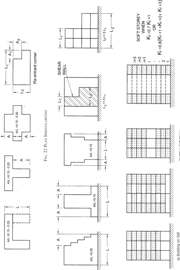
a) Plan irregularities — These are defined in
Table 4 of the Code as follows: 1) Torsion irregularity, 2) Re-entrant corners, 3) Diaphragm discontinuity, 4) Out of plane offsets, and 5) Non-parallel systems.
The geometric irregularities in building plans which can be easily identified are shown in Fig. 22.
These irregularities enhance the overall damage (increased grade of damage for example at re-entrant corners). Such a building may be recommended for detailed evaluation. b) Vertical irregularities — These are defined in
Table 5 of IS 1893 (Part 1). The following vertical irregularities may be seen in masonry buildings (see Fig. 23).
1) Mass irregularity
2) Vertical geometric irregularity
3) In-plane discontin uity in vertical elements resisting lateral forces. If any of these irregularities are noticed, the building should be recommended for detailed evaluation.
A-7.2.4 Falling Hazard
Where such hazards are present, particularly in Zones IV and V, recommendations should make reference to these in the survey report as indicated.
A-7.2.5 Type of Foundation Soil
IS 1893 (Part 1) defines three soil types hard/stiff, medium and soft. No effect of these is seen in the design spectra of short period buildings, T < 0.4, covering all masonry buildings, hence the effect may be considered not so significant.
F IG . 23 V E R TICAL I RREGULARITIES F IG . 22 P LAN I RREGULARITIES a) Building on Still