HP Verified Reference
Architecture for Microsoft Lync
Server 2013 Enterprise (5,000
user) enabled by SDN
Table of contents
Executive summary ... 3
Introduction ... 4
Lync solution design ... 4
Solution overview ... 5
Solution at a glance ... 6
HP devices used for Lync Server 2013 RA ... 6
HP ProLiant servers ... 7
Network configuration for lab ... 8
Designing the solution: architecture planning tools used ... 12
Capacity and sizing ... 13
HP Sizer for Microsoft Lync Server 2013 ... 14
Microsoft Lync Server 2013 Capacity Calculator... 15
Microsoft Lync Server 2013, Planning Tool ... 16
Testing scenarios and results ... 16
How the test was performed ... 16
Analyzing the test results ... 17
System performance... 18
Lync Server Role performance ... 20
Test results ... 27
Overview of deployment guidance ... 28
Configuration overview graphic ... 28
Lync Server 2013 environment ... 29
Lync 2013 client simulation environment ... 29
Lync network ... 30
SDN solution for Lync Server 2013 ... 31
Site configuration ... 36
High Availability ... 36
Software configuration ... 36
Server configurations ... 37
Lync Stress and Performance Tool ... 43
Arcatech emutel | Harmony PSTN Simulator ... 44
Bill of materials ... 44
Summary ... 49
Implementing a proof-of-concept ... 49
Appendix 1 – Performance counters ... 50
Appendix 2 – Workload configurations ... 52
For more information ... 58
HP Networking resources... 58
Microsoft Lync Server resources ... 58
Executive summary
As business technology needs change at an ever-increasing pace, it is difficult to quickly implement complex solution designs. HP and Microsoft® are positioned to help you deploy a stable, flexible and highly available Microsoft Lync Server 2013 infrastructure to serve your communications needs. HP and Microsoft have products, solution design and
implementation knowledge that build on their strong foundation and deep experience. The HP products contained in this reference architecture include:
• HP ProLiant DL360p and DL380p servers
• HP Networking gear for your datacenter and branch office wired and wireless Ethernet needs
The Microsoft products contained in this reference architecture include:
• Microsoft Lync Server 2013 Enterprise Edition
• Microsoft Windows Server® 2012 R2
These products are critical to the implementation of your Lync communication platform. Effective use of new features means that you can develop, implement, monitor and maintain all of the hardware components and applications in the solution. As newer components are made available or as additional functionality is required, it can be seamlessly added to the existing infrastructure.
The HP Verified Reference Architecture for Microsoft Lync Server 2013 Enterprise (5,000 user) is based on a tested and validated physical architecture with the following server and networking roles:
• Microsoft Lync 2013 Front End servers (with Mediation role collocated)
• Lync Server 2013 monitoring servers
• SQL Server 2012 Enterprise Service Pack 2 (Lync Back End servers)
• Lync Edge servers
• Office Web Apps server
• Lync 2013 persistent chat servers
• Lync 2013 director servers
• HP Software Defined Networking (SDN) / Virtual Application Network (VAN) controller with HP Networking Optimizer
• HP Networking SDN Manager
• HP Networking Modular Services Router (MSR)
• Arcatech emutel | Harmony PSTN simulator
Each of the machines that hold server roles is hosted on a physical ProLiant DL rack mounted server.
HP Software Defined Networking (SDN) is deployed in this solution to optimize Lync network traffic over HP’s OpenFlow compliant networking components. Optimization of Lync network traffic is based on the particular type of communication in use during a conversation including Instant Messaging, Presence, Audio, Video and Application Sharing.
The Microsoft Stress and Performance Test Tool for Lync Server 2013 was used for validation of Lync client workloads in testing ranging from 1.5 hours to 12 hours. This reference architecture (RA) is based on HP ProLiant DL380p Gen8 servers with internal drive cages for storage requirements and HP Networking devices, such as the HP 3800-48G-PoE+-4SFP+ Switch, the HP 10508 Core Switch, and the HP MSR50-60 Router, a Multi-service Router with E1, FXS and FXO ports. The results of the testing performed shows that the server and network devices selected for the reference architecture support a Microsoft Lync Server 2013 workload for 5,000 users during normal operational conditions as well as in multiple failure scenarios. This white paper provides details on the selection and configuration of the physical ProLiant servers that host the Lync roles, HP Networking devices and SDN to meet the solution requirements.
For more information, please visit:hp.com/go/uc.
Note
For more information on “Lync Server 2013 User Models” please visit: http://technet.microsoft.com/en-us/library/gg398811.aspx
Target audience: This white paper is intended to assist IT decision makers, Lync architects and Microsoft® Windows® engineers involved in the planning, deployment and management of a physical deployment of Lync Server 2013 infrastructure using HP ProLiant servers with HP Networking components.
Document purpose: The purpose of this document is to describe a recommended architecture/solution, highlighting
recognizable benefits to technical audiences.
This Reference Architecture describes testing performed in March 2015.
Introduction
The HP RA for Microsoft Lync Server 2013 Enterprise (5,000 user) provides a tested Lync Server 2013 solution that is designed to support 5,000 corporate users. The Lync Server 2013 product is part of the Unified Communications (UC) platform from Microsoft that also includes Microsoft Exchange Server 2013 and SharePoint 2013. The Microsoft UC platform is an integrated set of technologies that enables users within a company to efficiently communicate with their peers and with those outside of their company. With the Microsoft UC platform, the 2013 versions of Lync, Exchange and SharePoint are closely integrated and allow users with Microsoft Office products to use resources such as email and presence, document management and storage in a seamless fashion.
The physical deployment of Lync Server 2013 in a highly available design requires proper sizing and the use of
recommended best practices when sizing the server roles and network components. The design and sizing performed for this reference architecture has been tested as part of this project to ensure that it is capable of supporting 5,000 corporate users with the instant messaging and presence (IM&P), enterprise voice, dial-in and web conferencing with voice, video and application sharing Lync features during both normal operations and failure scenarios.
For most customers, designing and sizing a Lync Server 2013 implementation is a complex process emcompassing servers, storage and networking. This project delivers a basic implementation of Lync Server 2013 and a customer can use the tools discussed to customize the implementation to meet their needs.
This project also provides the outcome of functional and performance testing. The functional testing ensures that the components are able to work together as envisioned and the performance testing ensures that the solution is capable of supporting 5,000 users with the desired features. Using this reference architecture as a guide, a customer can accelerate their design and implementation for Lync Server 2013 as part of an overall Microsoft UC strategy.
HP’s deep technical knowledge and experience help our customers build stable Lync infrastructure solutions to provide reliable access to Lync’s collaboration features. HP’s deployment experience and testing is documented in reference architectures to help customers to accelerate their solutions by providing an implementation blueprint.
Note
The HP RA for Microsoft Lync Server 2013 Mid Market (2,500 User) is available from: http://h20195.www2.hp.com/V2/GetDocument.aspx?docname=4AA4-7901ENW
Lync solution design
The HP reference architecture project solutions for Lync are driven by product and application experts across multiple HP business units to ensure that the solutions provided to customers incorporate expert knowledge from multiple sources representing the entire end to end infrastructure.
Key solution design points • Proper design and implementation
– Is sufficient performance provided for the Lync 2013 workload by the solution?
• Lync Stress and Performance Tool system validation
– Do all of the functional parts of the Lync 2013 solution work as expected? – Is the CPU load of the servers within design parameters when deployed? – Does the network infrastructure provide sufficient resources?
• Software Designed Networking
• High availability failure scenario testing
– Is the availability of Lync services maintained to design specifications during the failure of each component? – What service interruptions are expected as connections are failed over from one component to another in the HA
implementation? This speaks to the Service Level Agreement that a customer can target as well as setting expectation for the user experience.
Solution overview
The 5,000 user reference architecture equipment selection is based on HP ProLiant DL380p and DL360p Gen8 servers, the HP 10508 core switch, two HP 3800 distribution switches, an HP MSR50-60 Multi-service router and SDN Controller components.
The ProLiant DL servers depicted in Figure 1 are required to support the Lync Server 2013 functionality deployed for this highly available physical configuration. Figure 1 shows a logical configuration with the representative Lync server roles. If a specific server role is depicted as a pool, it has multiple servers and the lab tested server count can be found in the Server configurations section and the recommended server count for production implementation can be found in the Bill of materials section.
Figure 1. Configuration Diagram
The configuration used to support the reference architecture consists of server and networking hardware components as well as software components from both Microsoft and Hewlett-Packard.
Firewalls and a server holding the Lync Reverse Proxy role are required in a production deployment but were not deployed for testing in this lab configuration.
Front End Server Pool Microsoft Lync SDN Environment with API Persistent Chat Server Pool Office Web App Server Pool
Active Directory Server
Back End SQL Server and Mirror
Director server Array Edge Server Pool Microsoft Lync SDN Manager HP VAN SDN Controller with HP Network Optimizer Microsoft Lync Stress and Performance Tool Server (internal users) 3800 Switch OpenFlow Enabled 3800 Switch OpenFlow Enabled 10508 Switch
OpenFlow Not required
MSR 50-60 PSTN Gateway
Arcatech emutel™ | Harmony as PSTN Simulator Microsoft Lync Stress and Performance Tool Server (External users) Microsoft Lync Stress and Performance Tool Server (PSTN users) Microsoft Lync Stress and Performance Tool Server (internal users) VLAN 10 VLAN 30 VLAN 20 LACP Trunks E1
Solution at a glance
The HP RA for Microsoft Lync Server 2013 Enterprise (5,000 user) incorporates Lync features that a typical corporate user would access on a daily basis. The reference architecture is designed to provide high availability and resiliency in the event of failure. The integration of best practices from both HP and Microsoft in the solution design was a key factor.
Table 1. Solution at a glance
Description Value
Lync Clients 5,000
Active Users1 100%
Central Sites One
Remote Sites None
Instant Messaging and Presence Yes
Audio/Video, Dial-in and Web Conferencing Yes
Application Sharing and Data Collaboration Yes
Persistent Chat and Compliance Yes
Reverse Proxy Not Tested
Office Web Apps Yes
Monitoring Yes
Archiving Yes
PSTN Gateway Yes
Enterprise Voice-enabled Users 60%
PSTN Calls per Hour / Trunk Type 4 / E1
Phone calls using media bypass 0%
Remote User Connectivity / External Users Yes / 30%
Physical Infrastructure Yes
Lync Server 2013 version Enterprise Edition
High Availability/Redundancy2 Yes
Maximum Active Users per FE server 5,000
Storage Server Internal HDD
1 For testing purposes a concurrency rate for Lync users of 100% is used. In a typical corporate environment Lync concurrency is expected
to be in the 20% to 30% range.
2 For testing purposes High Availability/Redundancy was deployed for the Lync Server roles only and not for the network components.
HP devices used for Lync Server 2013 RA
High-level descriptions of each of the HP products used in the 5,000 user reference architecture are described in the following sections.
Note
The equipment described below should be taken as a reference only; a Lync solution is in no way limited to only these specific models. For example, the DL380p Gen8 is performing at par with the DL360p Gen8 but the DL380p Gen8 was positioned due to the flexibility it offers with six PCI expansion slots. The testing has been performed on the Gen8 models of the ProLiant servers and the Gen9 ProLiant servers are now available. The Gen9 servers can be implemented in place of the Gen8 servers by matching the respective processor, memory, networking and storage configurations.
HP ProLiant servers
ProLiant DL380p
The HP ProLiant DL380p is an unmatched investment that can handle today’s demanding compute requirements while safeguarding the investment for future growth. HP sets the standard of 2U 2-socket rack servers for the industry with the DL380p ProLiant server line. Substantial effort went into making the DL380p servers easy to service while packing the most up-to-date features into the small 2U form-factor. Overall, the DL380p is the perfect solution for today's growing
businesses and demanding datacenters due to its enhanced configuration flexibility, unmatched performance, and leading energy efficient design. In the event of a hardware failure, parts for the HP ProLiant DL380p servers are stocked in service depots around the world allowing for fast replacement to get your server back into production.
Figure 2. HP ProLiant DL380p Gen8
ProLiant DL360p
The HP ProLiant DL360p has the equivalent processing power as the ProLiant DL380p in a 1U 2-socket rack server. The DL360p server is as easy to service as the DL380p but with fewer PCI slots and fewer hard drives than the DL380p server. Figure 3. HP ProLiant DL360p Gen8
Both the HP ProLiant DL380p and DL360p servers support either Small Form Factor (SFF) or Large Form Factor (LFF) drives with both Solid State Drives (SSD) and Hard Disk Drives (HDD) with various capabilities to match your specific design needs. These drives run using the advanced technologies available on the HP Smart Array disk controllers.
Server network connectivity
ProLiant servers offer a selection of 1 and 10 GbE network interface cards which provide a variety of capabilities and the ability to change the cards as requirements evolve. Flexible LAN on Motherboard (FlexibleLOM) cards, shown below, are used to change the personality of the built-in networking ports in the server. The FlexibleLOM cards shown in figure 4 are replaceable without the use of tools.
Figure 4. FlexibleLOM cards for HP ProLiant DL servers
HP Ethernet 1Gb 4-port 331FLR FIO Adapter HP FlexFabric 10Gb 2-port 554FLR-SFP+ FIO Adapter
The HP Ethernet 1GbE 4-port 331FLR (LAN on Motherboard – LOM) and HP Ethernet 1Gb 4-port 331T (PCI) adapters selected for this configuration are used in both the DL380p and DL360p servers to provide multiple 1GbE ports for each physical server.
Network configuration for lab
Multiple network components are used in the deployment of a successful Lync server communications solution. The components range from HP networking datacenter switches, routers and management components to the distribution and edge switches that connect to your Lync enabled client devices over both wired and wireless technologies.
Lab network configuration
The network configuration consists of a combination of HP Networking hardware components and servers that host functions for the Lync infrastructure and is deployed into multiple network segments and one telephony segment:
• Internal network – the lab network that simulates the datacenter and client network connections.
• Edge Network – a border (or DMZ) network that is configured between internal network and the Internet. The Edge Network is located between two firewalls.
• Internet – a public network that is connected through the use of a Wide Area Network (WAN) connection to enable users outside of the company to connect to the Edge Network and access corporate services.
• SDN Network – a management network that is used for SDN control and switch management traffic.
• Public Switched Telephone Network (PSTN) – a telephony segment that is connected through the HP Multi-service Router (MSR) and can contain a Private Branch eXchange (PBX). This telephony segment connects to external telecom providers to allow calling external users of telephone services.
The HP 10508 core switch is the backbone of the network infrastructure and connects to the MSR50-60 and the HP 3800 switches that provide connectivity to the physical servers, routers and stress generation clients. For the scope of this testing, firewalls and the Lync Server 2013 reverse proxy server are not part of the configuration but are needed in a production Lync Server implementation.
HP Networking switches
The internal lab network contains an HP 10508 core switch with two 3800 distribution switches as the backbone of the network. This configuration provides the infrastructure necessary for testing the Software Defined Networking (SDN) features available for Lync Server 2013. The 10508 switch is configured with two 1GbE connections to each of the 3800 switches for connection redundancy. The 1GbE ports on each 3800 switch are connected to the ProLiant servers which allow access to the physical hosts that run the Lync server roles, the network management servers for SDN and HPN Intelligent Management Center and the tools servers which host the Lync Stress and Performance tools to simulate Lync client connections.
HP 10508 Switch
The HP 10508 Switch was used for core modular switching in the testing of the HP Networking 2-tier design selected for the 5,000 user reference architecture. This is a modular switch that supports virtualization modules, 10GbE core switching, PoE+, layer 3 routing and high availability features. The HP 10508 fits well for the 5,000 user design.
The HP 10508 Switch offers high performance, scalability, and a wide range of features in a high-availability platform that dramatically reduces complexity and provides reduced cost of ownership. As part of a unified wired and wireless network infrastructure solution, the 10508 switch provides platform technology, system software, system management, application integration, wired and wireless integration, network security, and the support that is common across HP modular and fixed-port switches. Together, they deliver an agile, cost-effective, high-availability network solution. With key technologies to provide solution longevity, the 10508 switch is built to deliver long-term investment protection without added complexity for network core, aggregation, and high-availability access layer deployments. It provides these capabilities while bringing to market the industry's first highly available switch with a lifetime warranty.
Benefits of the 10508 Switch
• Core, distribution, mission-critical access layer
• Advanced high-availability AllianceONE integrated applications and partner products
• Layer 2 switching, layer 3 services and routing and an intelligent edge feature set
• Enterprise-class performance and security
• Scalable 1/10/40 and 100 GbE connectivity
HP 3800 Switch Series modular switches
The HP 3800 Switch Series was used for access switching in the testing of the HP Networking 2-tier design selected for the 5,000 user reference architecture. The HP 3800 Switch Series is recommended for designs that go up to and include 5,000 users that are split across multiple 3800 switches.
The HP 3800 Switch Series is a family of nine fully managed Gigabit Ethernet switches available in 24-port and 48-port models, with or without POE+, and with either SFP+ or 10GBASE-T uplinks. The 3800 Switch Series utilizes the latest HP ProVision ASIC technology and advances in hardware engineering to deliver one of the most resilient and energy-efficient switches in the industry. Meshed stacking technology is implemented in the HP 3800 Switch Series to deliver chassis-like resiliency in a flexible, stackable form factor.
Figure 6. HP 3800 modular switch
Benefits of the HP 3800 Switch Series
• Fully managed Layer 3 stackable switch series
• Low-latency, highly resilient architecture
• RJ-45, SFP+, 10GBASE-T, PoE+, modular stacking
• Highly resilient meshed stacking technology
• OpenFlow compatible switch that supports SDN technology
• Industry-leading lifetime warranty
HP MSR Series router offerings
The HP MSR Series routers provide Wide Area Network (WAN) routing functionality within an HP FlexBranch Branch Office solution, supporting a large variety of WAN interfaces such as serial/T1/T3/E1/E3/ATM/xDSL/POS/CPOS/3G and protocols such as RIP/OSPF/IS-IS/BGP/MPLS/HSPA/WCDMA/IPv4/IPv6. The HP MSR Series routers have multiple models available for different price/performance/capability combinations. This variety of MSR versions allows the selection of models supporting small branch offices with only Ethernet connectivity up to large branch offices with needs for high performance and modularity, including OC-3/T3/E3 WAN bandwidth, security, resiliency, and scalability.
The HP MSR Series can be used as a SIP media gateway in a Microsoft Lync Server environment, providing:
• Analog and digital SIP media gateway
• Multiple interface types to connect to PSTN
• Modular and fixed configurations
• Integrated SIP stack
Benefits of the HP MSR Series routers
• Convergence of routing, switching, security, and voice
• Modular, multi-bus architecture provides high reliability and high performance
• Full line of enterprise modular routers for small offices to medium-large data centers
• Redundant power supply and hot swapping available on select models
• Unified management platform
• Common modules across many platforms
• Open application architecture enabled
• No extra license cost for features
• Within the HP FlexNetwork architecture, the HP MSR Series of routers is a major component of the HP FlexBranch reference architecture, providing:
– Integrated “all-in-one” with routing, switching, wireless LAN, 3G/4G, voice and security – Based on open standards (such as SIP) with modular interface options (WAN/LAN/voice) – Broad range of WAN access interfaces with data rates up to OC-3
– Unified operating system (Comware) across all HP routers
– Single pane of glass management with HP Intelligent Management Center (IMC) – Multi-vendor, best of breed SIP-based UC connectivity
Benefits of HP MSR50-60 Series routers
• 4U with 6 FIC slots
• 2 ESM modules
• 1 VCPM Module
• Optional Power over Ethernet chassis with up to 24 PoE ports
• Optional DC power supply chassis
• Optional external Redundant Power Supply
• Same performance, resiliency, and features as HP MSR30-60 in a medium form factor
• Optional Session Border Controller (SBC) Lync Modules for branch office implementations Figure 7. HP MSR50-60 Series router
Designing the solution: architecture planning tools used
HP’s solutions for Lync enable the optimization of Lync traffic to ensure that customer experience is maintained at a high level. Lync is sensitive to network design and latency and if not properly deployed, users experience poor performance as the resource demands increase beyond a pilot group of users.
The following sections describe the key points that were considered while designing this solution. The architecture planning process is also described in length for the customer benefit.
Key points
• Deployment of a highly available Lync Server 2013 infrastructure
• Design incorporates Microsoft, HP best practices
• Physical hardware deployment aligns with Microsoft guidance
• High Availability and failover strategies are useful in maintaining a chosen Service Level Agreement
• Describes SDN feature integration into HP’s solution for Lync Server 2013
This project documents the deployment of Lync Server 2013 in a highly available configuration for 5,000 users on HP ProLiant DL360p and DL380p Gen8 servers. This reference architecture contains tested designs for a highly available Microsoft Lync 2013 deployment based on the Lync Server 2013 User Models as defined by Microsoft. The Microsoft Stress and Performance Test Tool for Lync Server 2013 validates the Lync client workloads in testing ranging from 1.5 hours to 12 hours.
Software products included in this RA:
• Microsoft Lync Server 2013 – Enterprise Edition
• Microsoft SQL Server 2012
• Microsoft Lync Stress and Performance Tool
• Microsoft Windows Server 2012 R2
• HP Network Optimizer
For this RA, a physical deployment model aligns with the Microsoft recommendation for large Lync deployments. This reference architecture (RA) contains HP ProLiant DL360p and DL380p Gen8 servers with internal drive cages for the required storage. The HP Networking (HPN) devices align with the HPN Reference Design guides and include devices such as the HP 10508 Core Switch, 3800 Distribution switches, and the HP MSR50-60 Router (multi-service Router with E1/T1 FXS and FXO ports). This RA includes a section describing the use of Software Defined Networking (SDN) components, the features that SDN enables and the firmware/software levels necessary to implement SDN.
Hardware products included in this RA:
• ProLiant DL360p and DL380p Generation 8 servers
• HP core and branch networking gear
• HP Modular Services Router (MSR) Lync gateway
• Arcatech emutel | Harmony PSTN Simulator
Customer value
This reference architecture is the second in a series of HP RAs providing deployment examples for Lync Server 2013 for Channel Partners, Technical Services (TS), customers and other skilled Lync solutions implementers. These projects provide tested solutions that demonstrate concepts and design decisions made while sizing a Lync infrastructure to assist in the development of Unified Communications offerings.
Figure 8 below shows a graphical overview of the logical configuration for this HP Verified Reference Architecture for Microsoft Lync Server 2013 Enterprise (5,000 user). The configuration is split into multiple network areas: internal network, SDN Control network and Internet/Edge (DMZ) network.
Figure 8. Logical Configuration Diagram
Capacity and sizing
The sizing of a solution design is critical to ensure that your customer’s needs are fulfilled by the design choices you make. This process requires the ability to work with your customer to understand the features that they need incorporated in their design and how those needs are met and prioritized against real world constraints such as cost. In an ideal situation, there are no tradeoffs to be made, cost is not a factor and we can size the solution to include all of the features we would like to have. Reality tempers those solution designs by striking a balance between prioritization of features based on business requirements and the cost of various solutions versus the budget allocated to the project, integration with existing systems and existing infrastructure capacity. Each customer has a range of solutions that will meet their needs with varying degrees of completeness. Each customer’s solution is driven from a combination of their Service Level Agreement (SLA) and business requirements that establish the foundation of the required feature set, level of high availability and disaster recovery up to a feature set which includes the nice to have features that fit within the project budget.
Lync Server 2013 can be deployed as Standard Edition with simple availability features or as Enterprise Edition with a full complement of availability features. Lync Server 2013 can be deployed in a virtualized environment or in a physical
environment where each deployment methodology presents pros and cons. With the variety of deployment options for Lync Server, sizing tools exist to assist with performing “What if” design variations. Once the basic workload and site structure information is described in the tool, changes can be made to determine the solution outcome; for example, the number of blade or rack mount servers required given a specific processor or memory configuration choice.
Lync Edge
Reverse Proxy Office Web Apps
Lync Front End and File Shares
Mediation (co-located)
Lync Monitoring
Persistent Chat
SQL Back End HP Network Optimizer / VAN Controller
Gateway Lync Director Internet PSTN SDN Manager Customer Provided Firewalls Reverse Proxy
Several tools exist to assist with the design and sizing of a Lync Server 2013 implementation. The tools include the HP Sizer for Microsoft Lync Server 2013 that generates configuration details, and a bill of materials containing HP server and storage components across multiple site configurations based on a series of questions. The HP tool has the ability to save a defined workload and then change a variable such as the substitution of a four-socket ProLiant DL server for a two-socket ProLiant DL server and determine the effect that the change has on the solution design and cost. Another tool, the Microsoft Lync Server 2013 Capacity Calculator, provides a set of inputs for the various Lync Server 2013 workload components and outputs the quantity of servers needed for each server role. Microsoft also provides the Lync Server 2013 Planning Tool that assists with the definition of site topology, the server roles and hardware needed for each site. Each tool is discussed below.
HP Sizer for Microsoft Lync Server 2013
The HP Sizer for Microsoft Lync Server 2013 provides an analysis of the HP server and storage hardware needed to implement the features that you select in the Sizer. The site names and number of users homed in each central site are entered and Lync features are selected with the use of checkboxes. The tool then allows the configuration of the Enterprise Voice feature and co-location configuration for roles. Branch office information is entered including the number of branch offices and the users in each as well as configuration details for the external communication connections that each branch office has available. The specific type of server is selected from the Role Server Options page and can range from allowing the Sizer to recommend the servers or the selection of specific features such as rack mount (DL) servers or BladeSystem servers (BL). At each step of the process, the Solution Preview button shows the current configuration based on the inputs and selections that have been entered. After working through each of the pages in the Sizer and clicking on the Finish button, the Sizer performs the full set of calculations and generates multiple views of the configuration recommendations. A Bill of Materials (BOM) is generated that can be provided to your HP sales specialist for quotation of the server and storage components along with detailed configuration views, graphical topology views and the ability to save the solution to a file for later reference. The HP Sizer for Microsoft Lync Server 2013 is available at: hp.com/solutions/microsoft/lync2013/sizer Figure 9. HP Sizer for Microsoft Lync Server 2013
Microsoft Lync Server 2013 Capacity Calculator
The Microsoft Lync Server 2013 Capacity Calculator is an Excel spreadsheet developed by Microsoft that allows for the input of the number of users and is pre-configured with a mixture of Lync Server 2013 workloads. The workloads are specified by the percentage of the total user population that uses a specific Lync feature. The defaults in the tool can be used as a starting point or custom values can be entered into the orange cells if you have more accurate data for your environment. The tool then outputs a recommendation for the minimum quantity of servers for each server role. Since this solution includes high availability features for the Lync Server roles, additional servers have been incorporated into the design to ensure Lync services are available in a failure situation.
The Microsoft Lync Server 2013 Capacity Calculator is available from the Microsoft download site: microsoft.com/en-us/download/details.aspx?id=36828
Figure 10. Microsoft Lync Server 2013 Capacity Calculator
Note
We set the value for media bypass from the default of 65% to 0% which changes the concurrent calls to 397. This is done to increase the load on the Lync environment to ensure that the test cases are using the highest level of Lync server resources possible.
Microsoft Lync Server 2013, Planning Tool
The Microsoft Lync Server 2013, Planning Tool, developed by Microsoft, provides the ability to describe a Lync site configuration and feature selection that is specific to your company’s requirements and then matches the number of servers and networking components needed to implement the overall topology. The tool starts the design process with an interview to assess the Lync features and high availability options and proceeds through a site description covering central and branch sites and the features each site has enabled. The tool then asks for the Web Conferencing, Voice features, Exchange Unified Messaging and other Lync features to ensure an accurate implementation.
The Microsoft Lync Server 2013, Planning Tool is available from the Microsoft download site: microsoft.com/en-eg/download/details.aspx?id=36823
Figure 11. Microsoft Lync Server 2013, Planning Tool
Each of the tools is run and the results compared to ensure that the sizing is accurate. The HP tool provides server and storage results based on the specific capabilities provided by ProLiant servers. The Microsoft sizers provide sizing based on a generic server platform that must be adjusted for the specific hardware that you wish to use to ensure accurate sizing.
Testing scenarios and results
The Lync Server 2013 solution incorporated the Lync server roles described in the Server configurations section. The PSTN environment was set up using HP MSR Media Gateways and PSTN environment simulators. The SDN environment was configured and integrated into the Lync lab configuration. The Lync users were simulated using the Microsoft Stress and Performance Test tools. The test tools generated load on the Lync environment that consisted of all Lync workloads that the tool supported. The performance parameters were recorded on each of the Lync servers and the monitoring server for overall system performance. Test results were also captured from SDN components and the Arcatech emutel | Harmony PSTN simulator.
How the test was performed
The 5,000 users were divided into two groups of 2,500 each to divide the Lync user connections across the two HP 3800 switches. The Lync Server 2013 Stress and Performance Tool (often referred to as LyncPerfTool) was used to simulate the Lync workloads. The following scenarios were tested:
1.1: 5,000 users with 30% of users enabled for Enterprise Voice
2.1: 5,000 users with 60% of users enabled for Enterprise Voice
2.2: 5,000 users with 60% of users enabled for Enterprise Voice and 398 Concurrent UC-PSTN calls
3.1: 5,000 users with 60% of users enabled for Enterprise Voice and 398 Concurrent UC-PSTN calls (Failover with loss of 1 Lync FE Server)
3.2: 5,000 users with 60% of users enabled for Enterprise Voice and 398 Concurrent UC-PSTN calls (Failover with loss of 1 Lync SQL Server)
3.3: 5,000 users with 60% of users enabled for Enterprise Voice and 398 Concurrent UC-PSTN calls (Failover with loss of 1 Lync Edge Server)
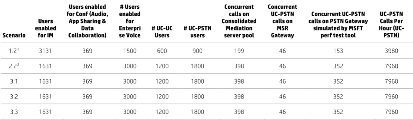
For each of the above scenarios, the following table shows the user distribution for each type of workload: IM&P, Enterprise Voice (UC-UC and UC-PSTN), Conferences (including different modalities: Audio, Application Sharing and Data Collaboration).
Note
The Data Collaboration load works for internal Lync users. In the lab configuration, neither a reverse proxy or load balancer was configured for testing therefore the Lync Edge connected users did not upload content to the conference/meeting.
Table 2. User Distribution Per workload (5,000 Lync users)
Scenario
Users enabled
for IM
Users enabled for Conf (Audio,
App Sharing & Data Collaboration) # Users enabled for Enterpri
se Voice # UC-UC Users # UC-PSTN users
Concurrent calls on Consolidated Mediation server pool Concurrent UC-PSTN calls on MSR Gateway Concurrent UC-PSTN calls on PSTN Gateway simulated by MSFT perf test tool
UC-PSTN Calls Per Hour (UC-PSTN) 1.21 3131 369 1500 600 900 199 46 153 3980 2.22 1631 369 3000 1200 1800 398 46 352 7960 3.1 1631 369 3000 1200 1800 398 46 352 7960 3.2 1631 369 3000 1200 1800 398 46 352 7960 3.3 1631 369 3000 1200 1800 398 46 352 7960
1 The user distribution for scenario 1.1 was the same as scenario 1.2 2 The user distribution for scenario 2.1 was same as that of 2.2
The performance parameters at the individual Lync server role and overall system level performance were captured. The details are discussed in the test results analysis section below.
Analyzing the test results
The test results data is collected from various parts of the test environment and is compared with Key Health Indicator (KHI) thresholds. The environment is designed to handle the Lync load during both normal and failure scenarios. The Key Health Indicators show if the test results are staying within the KHI threshold limits for each test performed.
The following types of data are collected:
• System level – This data shows the overall health of the Lync environment and includes the following reports: – System usage data
– Call diagnostic summary – QoE performance
• Individual Lync Server role level – This data is collected for each Lync server role and compared with KHI thresholds. The type of data includes:
– “Performance Data”: The system performance data is collected from each Lync server role – “Latency Data”: This includes the “Queue latency” and “Sproc latency” for Front End server role
• Performance metrics collected from SDN Controller – This data includes: – QoE Metrics: Shows the number of Good, Acceptable or Bad quality calls
– Concurrent Session information: Shows the number of concurrent sessions that are controlled by the SDN controller over a period of time
– Lync SDN Manager Status: Shows the connectivity status of the SDN Managers with the SDN controller – Session Info: per session details include caller IP/Port, callee IP/Port, time, DSCP value configured, DSCP value
expected and most importantly QoE status with Jitter and Mean Opinion Score (MOS) score that gives us quality of each Lync session
• The UC-PSTN call data captured from Arcatech emutel | Harmony PSTN simulator
System performance
System usage matrix
This data contains the following system usage parameters: Total number of users that logged into the system, total peer-to-peer sessions and total conferences, as well as detailed information on the number of IM sessions, audio sessions, video sessions, application sharing sessions and PSTN sessions.
Call diagnostics summary
This data shows how the Lync environment performed in terms of successfully processing the entire workload. The data collected shows the number of total sessions processed by the system and failure rate per modality (IM, Audio, Application Sharing and A/V conference) for peer-to-peer calls and conferences.
Figure 13. “Call Diagnostics Summary Report” for scenario 3.1
Media Quality Diagnostics
This data shows the overall media quality of the entire Lync environment. It shows the number and percentage of poor quality calls for peer-to-peer and conference sessions.
Figure 14. Media Quality Diagnostics for one scenario 2.2
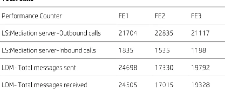
DNS load balancing performance
This data shows how sessions were distributed evenly across the servers in the pool by the DNS load balancer. The following table shows that the sessions were balanced almost equally across the three Lync Front End servers in the pool.
Table 3. DNS load balancing performance matrix for scenario 2.2
Total Calls
Performance Counter FE1 FE2 FE3
LS:Mediation server-Outbound calls 21704 22835 21117
LS:Mediation server-Inbound calls 1835 1535 1188
LDM- Total messages sent 24698 17330 19792
Lync Server Role performance
CPU utilization, memory and network utilization
The following data matrix shows the CPU, memory and network utilization per Lync server role for the test scenarios both for SDN and non-SDN types of configuration. In the non-SDN configuration type, OpenFlow was disabled, so the HP Network Optimizer/VAN controller processed the messages received from SDN Managers but no traffic prioritization was done. The performance values reported are good and well below the thresholds.
Table 4. Average CPU, memory, network usage per Lync Server Role (FE, SQL and Edge servers) in SDN Mode
Lync Front End Servers Lync Back End/SQL Servers Lync Edge Servers
Scenario CPU % used Average Memory Used Average (GB) Network Used Average (Mbps) CPU % used Average Memory Used Average (GB) Network Used Average (Mbps) CPU % used Average Memory Used Average (GB) Network Used Average (Mbps) - Internal Network Used Average (Mbps) - External 1.1 16 -19 8.5 – 10 3.5 – 4.5 0.3 38 0.215 1.5 2 0.115 0.149 1.2 14 - 30 8.5 – 10 7.9 – 8.7 0.5 28 0.252 1.5 2 0.121 0.147 2.1 19 - 28 6.9 – 7.5 7.5 – 7.7 0.6 38 0.226 1.33 2 0.104 0.122 2.2 42 – 56 7.5 – 8.5 14.7 – 15 0.7 32 0.237 1.4 2 0.129 0.125 3.1 54 – 63 17 – 18 19.2 – 19.4 1.32 40 0.23 1.27 2 0.085 0.087 3.2 38 – 53 13 – 20 13.1 – 13.6 0.668 43 0.177 1.3 2 0.107 0.125 3.3 46-55 15 - 17 15.5 – 16.4 0.75 43 0.237 1.4 2 0.123 0.115
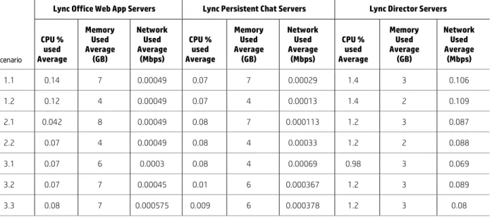
Table 5. Average CPU, Memory, Network usage per Lync Server Role (Webapp, PChat and Director server) in SDN Mode
Lync Office Web App Servers Lync Persistent Chat Servers Lync Director Servers
Scenario CPU % used Average Memory Used Average (GB) Network Used Average (Mbps) CPU % used Average Memory Used Average (GB) Network Used Average (Mbps) CPU % used Average Memory Used Average (GB) Network Used Average (Mbps) 1.1 0.14 7 0.00049 0.07 7 0.00029 1.4 3 0.106 1.2 0.12 4 0.00049 0.07 4 0.00013 1.4 2 0.109 2.1 0.042 8 0.00049 0.08 7 0.000113 1.2 3 0.087 2.2 0.07 4 0.00049 0.08 4 0.00033 1.2 2 0.088 3.1 0.07 6 0.0003 0.08 4 0.00069 0.98 3 0.069 3.2 0.07 7 0.00045 0.01 6 0.000367 1.2 3 0.089 3.3 0.08 7 0.000575 0.009 6 0.000378 1.2 3 0.08
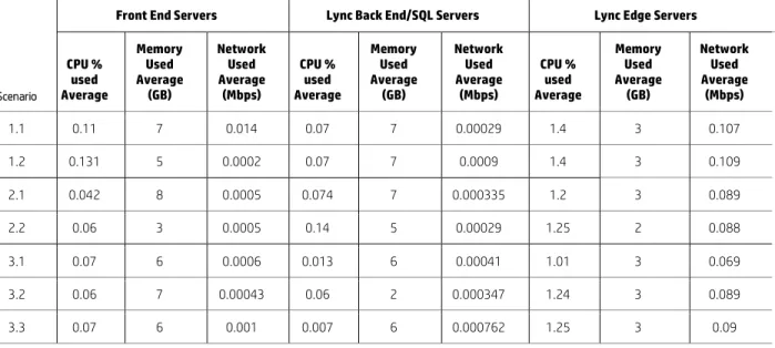
Table 6. Average CPU, Memory, Network usage per Lync Server Role (FE, SQL and Edge servers) in Non-SDN Mode
Front End Servers Lync Back End/SQL Servers Lync Edge Servers
Scenario CPU % used Average Memory Used Average (GB) Network Used Average (Mbps) CPU % used Average Memory Used Average (GB) Network Used Average (Mbps) CPU % used Average Memory Used Average (GB) Network Used Average (Mbps) - Internal Network Used Average (Mbps) - External 1.1 10.5 - 13 12.5 – 14.0 3.5 – 4.5 0.3 38 0.215 1.5 2 0.115 0.149 1.2 19.41 – 32.35 12.5 – 14.0 8.3 – 8.6 1.39 35 0.258 1.6 2 0.121 0.15 2.1 20.5 – 33.5 9.5 – 10.5 8.8 – 9.7 0.7 39 0.223 1.37 2 0.113 0.126 2.2 42 - 58 9.0 – 10.5 14.7 – 15.6 0.7 29 0.237 1.4 2 0.12 0.126 3.1 56.2 – 65.15 13 – 14 21.1 – 22 0.73 36 0.231 1.12 2 0.085 0.097 3.2 44 – 58 14 – 15 14.9 – 15.5 0.702 39 0.161 1.5 2 0.107 0.125 3.3 41 - 55 13 – 15 13.7 – 14.8 0.69 38 0.237 1.59 2 0.131 0.134
Table 7. Average CPU, Memory, Network usage per Lync Server Role (Webapp, PChat and Director server) in Non-SDN Mode
Front End Servers Lync Back End/SQL Servers Lync Edge Servers
Scenario CPU % used Average Memory Used Average (GB) Network Used Average (Mbps) CPU % used Average Memory Used Average (GB) Network Used Average (Mbps) CPU % used Average Memory Used Average (GB) Network Used Average (Mbps) 1.1 0.11 7 0.014 0.07 7 0.00029 1.4 3 0.107 1.2 0.131 5 0.0002 0.07 7 0.0009 1.4 3 0.109 2.1 0.042 8 0.0005 0.074 7 0.000335 1.2 3 0.089 2.2 0.06 3 0.0005 0.14 5 0.00029 1.25 2 0.088 3.1 0.07 6 0.0006 0.013 6 0.00041 1.01 3 0.069 3.2 0.06 7 0.00043 0.06 2 0.000347 1.24 3 0.089 3.3 0.07 6 0.001 0.007 6 0.000762 1.25 3 0.09
Change in user distribution observations with respect to workload
• 30% Enterprise Voice (Default) to 30% Enterprise Voice (198 concurrent UC-PSTN calls) - (Scenarios 1.1 and 1.2): – Front End servers: Average CPU utilization on Front End servers was increased by about 12% (19% Avg. for 1.1 vs. 30%
for 1.2). Almost the same amount of memory (<10GB) and network bandwidth was used in both scenarios. The additional CPU utilization was attributed to the fact that there was an increase in the UC-PSTN workload. – The resource usage on all other Lync server roles was insignificant. There was no change in the Queue and Sproc
latency.
• 30% Enterprise Voice (198 concurrent UC-PSTN calls) to 60% Enterprise Voice (396 UC-PSTN concurrent calls) - (Scenarios 1.1 and 2.2):
– Front End Servers: CPU utilization increased by about 25% (14-30% versus 42-56%). Memory usage was almost the same (<10GB). Network usage increased marginally (by about 8Mbps). The increase in CPU utilization can again be attributed to the increase in the UC-PSTN workload.
– The resource usage on all other Lync server roles was insignificant. The Queue and Sproc latencies increased slightly (Queue latency increased by about 1ms and Sproc latency by about 7%).
• Lync Front End server Failover (Scenario 3.1):
– Front End servers: The CPU usage was up by about 10% per FE (Average utilization on remaining FEs was about 54-63%). The memory usage increased about 10GB (about 17-18GB was used). There was marginal increase in network usage.
– The resource utilization on the SQL back end servers increased slightly but all other Lync servers were used
insignificantly. The Queue and Sproc latencies increased more than in scenario 2.2. (Queue latency increased to 8.24% and Sproc latency was about 63% max., with both well within the thresholds). This significant increase in latency is due to the increase in wait time for messages to get processed. This leads to the conclusion that if more workload is thrown on the system, latency can shoot up and needs consideration especially during failover situations.
• SQL Failover (Scenario 3.2):
– Front End servers: Utilization was almost the same as scenario 2.2 (60% EV without failover) on Front End servers except for an increase in memory usage (about 7GB). There was a slight increase in CPU utilization (about 0.5%) and memory usage (about 10GB) on the remaining SQL server. The latencies were of course increased (Queue latency increased to 13% and Sproc latency was about 48% max., both well within the thresholds). This increase in latencies was obviously for more waiting time needed for messages to get processed.
• Edge Failover (Scenario 3.3):
– There was no significant change in the resources utilization on all the Lync server roles. Latencies were increased slightly (Sproc latency was found to be about 47%). There was no significant change in resources utilization maybe because Web conf load was not tested.
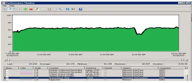
The following screenshot shows the CPU utilization from one of the Lync Front End servers during the Front End failover scenario. The CPU utilization is well below the recommended value (up to 75%). The momentary spikes are expected under full workload condition but average CPU utilization is somewhere around 65%. As expected, the CPU utilization is slightly higher (but within the limits) in the FE failover scenario than the normal scenarios where all FEs are up and running. This is due to the extra load that the remaining two active Front End servers have to carry due to failure of one of the Lync Front End servers.
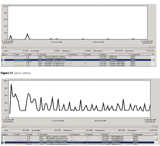
Latency
The following table shows the Queue and Sproc latency for the user services database captured on the Lync Front End server. The Average Queue and Sproc Latency is shown to be well below the allowed threshold value of 100ms.
• Queue Latency: It is the amount of time (in milliseconds) that it takes for a request to leave the Lync Front End Server’s queue towards the Back End database.
• Sproc Latency: It is the amount of time (in milliseconds) that it takes for the SQL server database to process the request. This performance value is collected from the time the request leaves the Lync Front End Server queue until that request returns.
Table 8. Queue and Sproc Latency (captured from FE servers) in SDN Mode
Front End Servers
Scenario Queue Latency Average (ms) Sproc Latency Average (ms)
1.1 0.045 – 1.73 15.51 – 23.83 1.2 0.06 – 1.73 20.42 – 27.32 2.1 0.054 – 1.12 18.65 – 24.7 2.2 0.064 – 1.18 22.8 – 34.8 3.1 1.29 – 8.24 48.02 – 63.08 3.2 3.2 – 13.5 31.7 – 48.0 3.3 0.10 – 1.8 29.8 – 47.1
Table 9. Queue and Sproc Latency (captured from FE servers) in Non-SDN Mode
Front End Servers
Scenario Queue Latency Average (ms) Sproc Latency Average (ms)
1.1 0.05 – 0.16 16.05 – 23.32 1.2 0.05 – 0.17 20.87 – 27.65 2.1 0.029 – 1.5 22.7 – 29.8 2.2 0.064 – 1.4 23.52 – 32.39 3.1 0.2 – 1.6 27.25 – 55.33 3.2 0.33 – 2.9 28.67 – 44.42 3.3 0.6 – 2.8 27.7 – 44.0
The following figures show screenshots from a Front End server for Queue and Sproc latency for one of the scenarios mentioned above, the average latency is well below the threshold (<100ms).
Figure 16. Queue Latency
Figure 17. Sproc Latency
Performance data from SDN controller
The current version of the SDN controller shows the performance data in graphics format only. The following data is collected:
• QoE Matrix shows that all the sessions in the system were of Good Quality and no poor quality sessions were reported.
• The “SDN Manager Status” shows that all three SDN managers were configured and reachable from the SDN controller.
• The “Session Info” table shows the session data that was sent by SDN managers to SDN controller. This data is about source and destination IP/port information, the media type used for the session, the protocol used and the quality of the session. The “Quality data” shows that all sessions are Good quality (QoE status is PASS) with no jitter or packet loss found and MOS score of about 4.3 (any session with MOS score above 4 is treated as a good quality session).
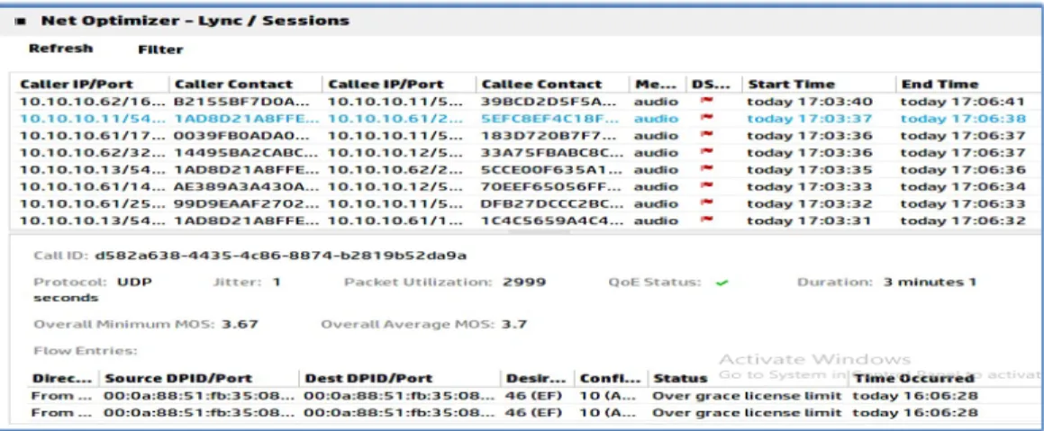
The following figure shows the “Session Info” captured from the SDN Controller Dashboard. It shows that the desired DSCP value set by the SDN Controller is 46, which means traffic prioritization was intended. The “Configured” value of DSCP will be shown as 46 for the sessions that were successfully prioritized. A “Configured” value of DSCP=10 shows the sessions with “Best Efforts”, meaning the session was not prioritized by the HP Network Optimizer/ VAN Controller.
Figure 18. SDN Controller Dashboard – Session Info for prioritized Sessions
Note
We used a license for SDN that allowed the management of 100 concurrent sessions. The number of active sessions constantly exceeded the HP Network Optimizer limit but the sessions over the license limit were still processed without applying DSCP marking by HP SDN Controller. In a production environment, it is important to purchase and install an HP Network Optimizer with a higher license limit to prioritize all the Lync sessions.
Figure 19. SDN Controller Dashboard – Session Info for Non-prioritized Sessions
The session QoE status shows “pass” with good quality. The Lync sessions were reported with good MOS, jitter and without packet loss.
The following graphical records were captured from HP Network Optimizer/VAN Controller during the tests. The QoE Matrix shows that all the calls were of good quality and no bad quality calls were reported from Lync.
Figure 20. QoE Matrix for Lync Sessions
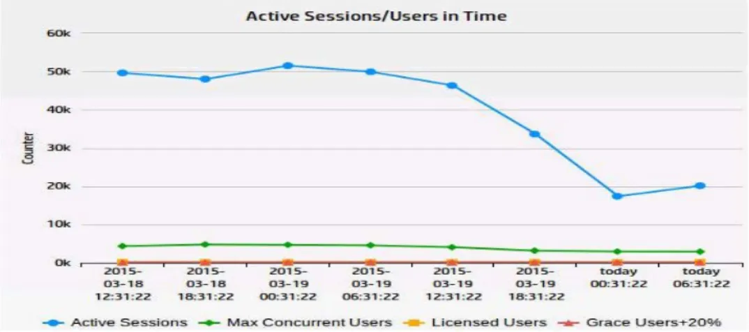
The Active sessions data shows how many active sessions were running at a variety of points in time on the SDN Controller. Figure 21. Active Sessions or Concurrent Users
The following graph shows the number of SDN Managers configured (3) and reachable (3) from HP Network Optimizer/VAN Controller. We tested two configurations:
• Configuration one: HA configuration with two SDN managers (one as a primary and one as secondary)
• Configuration two: Each LDL configured pointing to both SDN Managers
In non-HA configuration three LSMs were configured on three VMs and each LDL was configured to point to only one LSM. The results were the same as the HA configuration above.
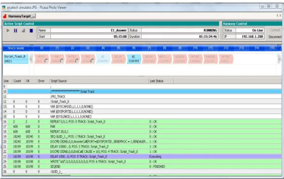
UC-PSTN calls data from Arcatech emutel | Harmony PSTN simulator
This data shows that the Arcatech emutel | Harmony PSTN simulator successfully processed all of the UC-PSTN calls that were configured for it to generate or receive with Lync. No failures were reported.
Figure 23. Test result screenshot from Arcatech emutel | Harmony PSTN simulator
The result from the Arcatech emutel | Harmony PSTN simulator shows that there are multiple calls that are received from Lync and also sent from the simulator to Lync server. All the calls are pass and there are no errors or failures reported.
Test results
The following are the important observations from the test results that are reported.
Key observations
• For both normal and failure scenarios, the hardware resource usage (CPU utilization, memory usage, network usage, etc.) was well below the thresholds for all Lync servers roles.
• The latencies that are critical to Lync performance (Queue and Sproc latencies) were well below the thresholds.
• All Lync sessions reported good quality (Good MOS) without any jitter or packet loss.
• The Media Quality Diagnostics Matrix showed that all the peer-to-peer and conference calls were reported to have good quality with no bad quality calls reported.
• The main resource utilization is on the Lync Front End Servers. The resources consumed on all other Lync server roles were insignificant. Lync Front End server planning is critical for adequate configuration during failure scenarios. – Maximum CPU usage (less than 63% during Lync Front End Failover scenario), maximum memory used (less than
20GB), maximum network bandwidth used (20 Mbps)
– Latencies (Queue and Sproc Latency) were less than 63ms which is well below the threshold of 100ms
• If multiple Lync databases are to be collocated on the Back End servers, it is recommended to install additional memory on the backend SQL server (more than 64GB would be recommended for a 5,000 user configuration).
• The workloads that consume the most CPU cycles are Enterprise Voice UC-PSTN peer-peer calls and conferences as well as application sharing. The other workloads consume few CPU resources. Capacity planning for the Lync server roles needs to be done based on user distribution per workload. If more users are using PSTN and application sharing workloads then the CPU utilization shoots up significantly and may require the deployment of an additional Lync Front End server.
• The following observations are critical from a planning perspective:
– In the 30% Enterprise Voice scenario, we decreased the number of IM peer-to-peer users significantly (from 3,131 to 600) and found that there is no significant decrease in CPU usage (barely a 2% decrease). This was because the IM workload does not consume more CPU per user.
– When the UC-PSTN workload users and application sharing users were increased there was significant increase in CPU and other resource consumption.
– The “CoversationLengthInSec” for UC-PSTN calls, and other workloads as well, is a critical parameter to consider for planning. It was observed that if this value was set to standard 180 second for UC-PSTN calls (with other values set to default), the average CPU utilization on the Lync Front End servers was around 12% but when the conversation length was set to 900 seconds then to 1,800 seconds, the CPU utilization on the Lync Front End servers shot up to 90%. If the average length of conversation is as high as 900 seconds in your environment, then additional Lync Front End servers will be needed for the same number of users.
High availability observations
• Performance in all of the failover scenarios was good. This included the Lync Front End server failover, SQL Back End server failover, Lync Edge server failover, etc.
• Among all failover scenarios, the Lync Front End failover caused more resource usage and latency on the remaining Front End servers than the other failure scenarios. The CPU utilization on the remaining active Lync Front End servers was observed to have gone up to 65% and Sproc latency was found to have increased to 63% but did remain well below the thresholds.
• The load was evenly distributed across all the servers in the pool of Lync servers with DNS load balancing.
SDN observations
• The performance data shows that the Lync configuration performance was good and almost the same both with and without SDN.
• The HP Network Optimizer/ VAN Controller can process the number of active sessions that the license limit allows. Therefore acquire the permanent license capacity that will be adequate to process the number of expected active sessions. For the over-the-license-limit sessions, the API events still get processed but the DSCP markings won’t be applied by the HP Network Optimizer/ VAN controller.
• When the DSCP marking was applied by the SDN Controller (Desired and Configured DSCP=46), all the sessions reported an excellent quality with overall good MOS scores, without any jitter and no packet loss.
• Traffic prioritization by the SDN controller can also be tested by introducing artificial network impairments through network impairment generator tools to report bad quality sessions to the SDN controller and see that the SDN controller applies the DSCP markings to those sessions to convert them to good sessions. This was not tested in any of our scenarios.
Overview of deployment guidance
Configuration overview graphic
The graphic below shows an overview of the logical configuration for this HP Verified Reference Architecture for Microsoft Lync Server 2013 Enterprise (5,000 user). The configuration is split into multiple network areas: internal network, SDN Control network and Internet/Edge (DMZ) network.
The servers depicted in the diagram are needed to support the Lync Server 2013 functionality deployed for this highly available physical configuration and are deployed on ProLiant DL Gen8 servers. Figure 9 shows a logical configuration with the representative Lync server roles. If a specific server role is depicted as a pool, it has multiple servers and the true server count can be found in the Server configurations and Bill of materials sections.
Figure 24. Configuration Diagram
The configuration used to support the reference architecture consists of server and networking hardware components and software components from both Microsoft and Hewlett-Packard. The components and their roles are detailed below. For the specific server counts and details for each role refer to the Server configurations section.
Firewalls and a server holding the Lync Reverse Proxy role are needed in a production deployment but are not deployed for testing in this lab configuration.
Lync Server 2013 environment
The Lync environment is set up using the physical servers with different Lync roles deployed on them (as shown in Figure 24 with Lync server roles labels).
Lync clients connect to Lync Front end servers to make any voice, video or conference calls. The Lync clients (both Local and Remote) are simulated by Lync Server 2013 Stress and Performance Tool (LSS) on HP blade workstations.
The Lync Front End server has the LYNC SDN API integrated. The Lync Front End server communicates with HP SDN controller using LYNC SDN API. The Lync Monitoring Server role that is collocated on the Front End server, stores the Quality of Experience (QoE) data for call quality for each Lync session. The call quality Matrix data is sent by Lync Front End server to SDN controller through the LYNC SDN API.
Lync 2013 client simulation environment
The Lync 2013 client simulators are divided into three groups: local, remote and PSTN client simulators. The local users are simulated by two Microsoft Lync Server 2013 Stress and Performance Tool servers with one server configured on each 3800 network switch to allow testing of SDN processing of Lync Server sessions. The two Lync Server 2013 Stress and Performance Tool servers each simulate 2,500 local users. The remote users that connect to Lync through the Edge server are simulated by the Microsoft Lync Server 2013 Stress and Performance Tool deployed on a third server.
Front End Server Pool Microsoft Lync SDN Environment with API Persistent Chat Server Pool Office Web App Server Pool
Active Directory Server
Back End SQL Server and Mirror
Director server Array Edge Server Pool Microsoft Lync SDN Manager HP VAN SDN Controller with HP Network Optimizer Microsoft Lync Stress and Performance Tool Server (internal users) 3800 Switch OpenFlow Enabled 3800 Switch OpenFlow Enabled 10508 Switch
OpenFlow Not required
MSR 50-60 PSTN Gateway
Arcatech emutel™ | Harmony as PSTN Simulator Microsoft Lync Stress and Performance Tool Server (External users) Microsoft Lync Stress and Performance Tool Server (PSTN users) Microsoft Lync Stress and Performance Tool Server (internal users) VLAN 10 VLAN 30 VLAN 20 LACP Trunks E1
Test tool configuration
The following types of Lync users were used:
• Internal Lync users that connect with the Lync Front End Server Pool
• External or Remote Lync users that connect with the Lync Edge Server Pool
An additional Microsoft Stress and Performance test tool server was configured as PSTN Gateway simulator to process UC-PSTN calls and Figure 25 shows the two routes created for UC_UC-PSTN calls.
Figure 25. Configuration of UC-PSTN routes
Figure 25 shows how UC-PSTN routes are configured. On the Lync Front End server, Under Voice Routing Route, the four routes (global, Arca1, Arca2 and Arca3) map onto the Media Gateway MSR50-60. The GWsimulator Route maps to the PSTN Gateway simulated by the Microsoft Stress and Performance Test tool.
Lync network
The Lync network is formed by two HP 3800 switches and an HP 10508 switch. Three VLANs are created: VLAN 10, 20 and 30. The entire Lync environment (servers and clients) and SDN managers are on VLAN10. The SDN controller is on a separate VLAN (VLAN20). The Edge server and Remote Lync user client are connected to VLAN30. One of the HP 3800 switches has VLAN 10, 20 and 30, whereas another HP 3800 switch has VLAN 10 and 20. The HP 10508 switch has VLAN 10, 20 and 30 created on it.
The Lync environment (all the Lync servers and local Lync clients) are physically connected to one of the HP 3800 Switches. Each HP 3800 switch connects to 2,500 Lync clients. The SDN controller is also connected to the same switch physically. The Edge server and Remote Users client are connected to another HP 3800 switch (that has VLANs 10, 20 and 30 on it). The Arcatech emutel | Harmony PSTN simulator is connected to the HP 10508 switch through an HP MSR50-60 Media Gateway.
Figure 26. Network Configuration for the Lync RA for 5,000 users
The two 1 GbE uplink connections between each 3800 switch and the 10508 were configured as a link-aggregation group (LACP). On one of the 3800 switches, VLAN10 and VLAN 20 were tagged onto the trunk connecting to the 10508. On the other 3800 switch, VLAN10, VLAN20 and VLAN30 were tagged onto the trunk connecting to the 10508.
• Internal network (VLAN10): This network, with IP addresses in the range of 10.10.10.0/24, constituted all the Lync servers (including internal interface of the Edge server), Lync client simulators (two client machines simulating 2,500 users each), SDN Managers, and Active Directory servers.
• PSTN network (VLAN10 and PSTN): The PSTN set up consisted of the Media Gateway (deployed on HP MSR50-60) and PSTN simulators. There were two routes created for UC-PSTN calls. One route was formed by MSR50-60 (Media Gateway) and Arcatech emutel | Harmony PSTN simulator simulating the PSTN environment. Another UC-PSTN route was formed by Microsoft Lync Stress and Performance test tool that simulated the UC-PSTN Gateway and PSTN environment.
• SDN Manager and network switch network (VLAN20): This network, with IP addresses in the range of 20.20.20.0/24, contains the Microsoft Lync SDN manager and the two 3800 switches.
• Edge (DMZ) and Internet network (VLAN30): This network, with IP addresses in the range of 30.30.30.0/24, connects from the external interfaces of the Edge servers and is comprised of three parts: Access interface, A/V interface and Web interface that connect to a separate Lync Stress and Performance Tool server located on the 30.30.30.0/24 network to simulate the outside world where public IM and federated users are located.
Due to lab hardware availability, the MSR50-60 could route only 46 concurrent UC-PSTN calls. This was caused by the lack of availability of voice co-processor cards for installation into the MSR. The remainder of the UC-PSTN load from Lync was routed on the PSTN GW simulated by the Microsoft Lync Stress and Performance Tool server.
The PCM trunks configured between the MSR50-60 and the Arcatech emutel | Harmony PSTN simulator were E1 type.
SDN solution for Lync Server 2013
Microsoft Lync Server 2013 Software Defined Networking (SDN) functionality was added late in the project and used equipment that was available to deploy quickly. This resulted in the implementation of the SDN components in a non-optimal configuration. This configuration included the SDN high availability components but was not designed for non-optimal high availability. An example of this is the deployment of both Microsoft SDN manager virtual machines on the same physical Hyper-V host. The result was that failure of the virtual machine could be simulated but not the failure of the physical host.
Office Web Apps Server pool Lync Persistent Chat Pool Lync Front End pool
Lync Back End SQL pool
Lync Director pool Infrastructure Servers
Lync Edge Server pool
Lync Stress & Performance Tools Network Optimizer/ VAN Controller
Test Workstations
Lync PSTN Gateway Simulator
Lync Stress & Performance Tools Lync Stress & Performance Tools
SDN Managers 10.10.10.11
10.10.10.12 10.10.10.13
(Mediation, Archiving & Monitoring co-located on FE)
10.10.10.21 10.10.10.22 10.10.10.31 10.10.10.32 10.10.10.41 10.10.10.42 10.10.10.52 30.30.30.11 30.30.30.12 30.30.30.13 (access) (web) (av) 30.30.30.21 30.30.30.22 30.30.30.23 (access) (web) (av) 10.10.10.02 10.10.10.01 10.10.10.51 3800 Switch-A Top 3800 Switch-B Bottom 10.10.10.81 10.10.10.82 ARCA PSTN Simulator MSR 50-60 Gateway 10.10.10.71
(Archiving & Monitoring DB, Persistent Chat & Compliance
DB co-located on BE) (Active Directory & DNS Servers) 10508 Switch (External Users) 30.30.30.31 20.20.20.125 Not Configured 10.10.10.91 10.10.10.96 30.30.30.85 (Internal Users) 10.10.10.62 (Internal Users) 10.10.10.61 VLANs Configured on Switch
VLAN1: 192.168.1.0 VLAN 10: 10.10.10.0 VLAN 20: 20.20.20.0
IP Routes Configured on Switch
192.168.1.0/24 DG: 10.10.10.0/24 DG: 20.20.20.0/24 DG: Management Port
IP Address: 192.168.1.210/24
VLANs Configured on Switch
VLAN1: 192.168.1.0 VLAN 10: 10.10.10.0 VLAN 20: 20.20.20.0 VLAN 30: 30.30.30.0
IP Routes Configured on Switch
192.168.1.0/24 DG: 10.10.10.0/24 DG: 20.20.20.0/24 DG: 30.30.30.0/24 DG: Management Port IP Address: 192.168.1.211/24
VLANs Configured on Switch
VLAN1: 192.168.1.0 VLAN 10: 10.10.10.0 VLAN 20: 20.20.20.0 VLAN 30: 30.30.30.0
IP Routes Configured on Switch 192.168.1.0/24 DG: 10.10.10.0/24 DG: 20.20.20.0/24 DG: 30.30.30.0/24 DG: Management Port IP Address: 192.168.1.201/24 DG: Management Port IP Address: 192.168.1.202/24 DG: Management Port IP Address: 192.168.1.200/24 DG: LACP Trunk
VLAN 10 and VLAN20
10.10.10.118 10.10.10.126 Port 13 Port 12 Port 10 Port 47 Port 19 Port 18 Port 26 Port 27 LACP Trunk VLAN 10, VLAN20 & VLAN30