Belgacom b-box
Instructions for use
Version 1.0
TABLE OF CONTENTS
CHAPTER 1 INTRODUCTION ...4
About the Belgacom b-box ... 4
Telephony over IP... 4
CHAPTER 2 INSTALLATION ...6
Package Contents ... 6
System Requirements... 6
Hardware Description ... 6
Hardware Installation... 8
ADSL Connection... 8
Fast Ethernet Connection... 8
FXS Connection... 8
ISP Settings... 8
Connect the System... 8
Connect the ADSL Line... 8
Attach to Your Network Using Ethernet Cabling... 11
Connect the Power Adapter ... 11
CHAPTER 3 CONFIGURING THE CLIENT PC...12
TCP/IP Configuration ... 12
Configuring Your Computer in Windows 2000 ... 12
Obtain IP Settings From Your Belgacom b-box... 14
Manual IP Configuration ... 15
Disable HTTP Proxy... 15
Configuring Your Computer in Windows XP DHCP IP Configuration... 15
Obtain IP Settings from Your Belgacom b-box... 17
Disable HTTP Proxy... 19
Disable HTTP Proxy... 20
CHAPTER 4 CONFIGURING THE BELGACOM B-BOX...22
Navigating the Web Browser Interface... 22
Making Configuration Changes... 22
Setup Wizard... 23
Quickstart... 23
Configure your Telephone settings... 24
ADSL ... 26
Status... 27
Advanced Setup ... 29
Making Configuration Changes... 30
System Settings... 30
Time Settings ... 30
Password Settings ... 31
Remote Management ... 31
DNS... 32
WAN ... 33
ATM PVC... 33
ATM Interface ... 34
Clone MAC Address... 35
LAN ... 36
Wireless... 38
Wireless Settings... 38
Channel and SSID... 38
Access Control ... 40
Security ... 41
WEP ... 42
WPA... 43
802.1X... 45
Easy pairing ... 46
NAT ... 46
NAT Settings ... 47
Address Mapping ... 48
Virtual Server... 49
Special Applications ... 50
NAT Mapping Table... 52
Route ... 52
Static Route Parameters ... 52
RIP Parameter ... 53
Routing Table... 55
Firewall ... 56
Access Control ... 57
Access Control Add PC ... 57
MAC Filter... 58
URL Blocking... 59
Schedule Rule ... 61
Edit Schedule Rule... 61
Intrusion Detection... 62
DMZ... 66
SNMP... 67
Community ... 67
Trap ... 68
ADSL ... 69
ADSL Parameters ... 69
Status... 69
Telephony ... 72
Port Setting... 72
SIP Setting ... 73
Telephony Advanced Setting... 75
Dialing Plans... 76
Telephony Status... 77
Telephony Call Logs... 77
GLOSSARY ...86
SPECIFICATIONS ...89
CHAPTER 1 INTRODUCTION
Congratulations on your purchase of the Belgacom b-box. We are proud to provide you with a powerful yet simple communication device for connecting your local area network (LAN) to the Internet. For those who want to surf the Internet in the most secure way, this router provides a convenient and powerful solution. The Belgacom b-box also enables service providers to provide their residential and small office home office (SOHO)
customers with high-quality telephony service using traditional analog telephones and fax machines.
About the Belgacom b-box
The Belgacom b-box provides Internet access to multiple users by sharing a single-user account. It is a cost-efficient means for service providers to migrate their customers’ traditional analog telephones and fax machines onto IP-based networks. This new technology provides many secure and cost-effective functions. It is simple to configure and can be up and running in minutes.
Telephony over IP
Using Telephony over IP, instead of making calls over the regular telephone network, calls are made over computer (IP) networks, either through your Internet Service Provider’s connection or through your local network.
The basic steps involved in Telephony include the conversion of an analog voice signal to digital, the encoding and then compression of the signal into Internet Protocol (IP) packets. The Belgacom b-box is equipped with a digital signal processor (DSP), which segments the voice signal into frames and stores them in voice packets. Using the industry standard codecs, G.711, G.723.3 and G.729, these packets are encoded. These IP packets are then transmitted in accordance with Internet Engineer Task Force specification SIP over the Internet to their destination where the process is reversed.
Important information
• Please install and connect the product in the way as described in the chapter ‘Before You Start Guide’ only. This assures best installation results with the least technical hassles. • Please read this guide carefully before using the ADSL Wireless Base Station; and keep it for future reference.
• During set-up and installation, it may be helpful to have the instructions for your PC and other network components at hand.
Safety Precautions
• Do not expose the product to excessive moisture, rain, sand or heat sources.
• The product should not be exposed to dripping or splashing. No object filled with liquids, such as vases, should be placed on the product.
• Keep the product away from domestic heating equipment and direct sunlight.
• Allow a sufficient amount of free space all around the product for adequate ventilation. • Do not open this product. Contact your retailer if you experience technical difficulties.
Environmental information
All redundant packing material has been omitted. We have done our utmost to make the packaging easily separable into three mono materials: cardboard (box), polystyrene foam (buffer) and polyethylene (bags, protective foam sheet).Your set consists of materials that can be recycled if disassembled by a specialized company. Please observe the local regulations regarding the disposal of packing materials, exhausted batteries and old equipment.
Disclaimer
This product is provided by Philips ‘as is' and without any express or implied warranty of any kind of warranties, including, but not limited to, the implied warranties of
merchantability and fitness for a particular purpose are disclaimed.
In no event shall Philips be liable for any direct, indirect, incidental, special, exemplary, or consequential damages (including, but not limited to, procurement of substitute goods or services; loss of information, data, or profits; or business interruption) howsoever caused and on any theory of liability, whether in contract, strict liability, or tort (including negligence or otherwise) arising in any way out of the use of inability to use this product, even if advised of the possibility of such damages. Philips further does not warrant the accuracy or completeness of the information, text, graphics, illustrative examples links or other items can deviate from the product.
CHAPTER 2 INSTALLATION
Before installing the Belgacom b-box, verify that you have all the items listed under “Package Contents.” If any of the items are missing or damaged, contact your local distributor. Also be sure that you have all the necessary cabling before installing the Belgacom box. After installing the Belgacom box, refer to “Configuring the Belgacom b-box”.
Package Contents
After unpacking the Belgacom b-box, check the contents of the box to be sure you have received the following components:
• Belgacom b-box
• Power adapter
• One CAT-5 Ethernet cable
• Telephone patch cable
• One CD with drivers and documentation
Immediately inform your dealer in the event of any incorrect, missing, or damaged parts. If possible, please retain the carton and original packing materials in case there is a need to return the product.
System Requirements
You must meet the following minimum requirements:
• Internet access from your Internet Service Provider (ISP) using an ADSL line.
• A computer equipped with a 10 Mbps, 100 Mbps, or 10/100 Mbps Fast Ethernet card.
• TCP/IP network protocols installed on each PC that will access the Internet.
• A Java-enabled web browser, such as Microsoft Internet Explorer 5.0 or above installed on one PC at your site for configuring the Belgacom b-box.
Hardware Description
The Belgacom b-box contains an integrated ADSL modem and connects to the Internet or to a remote site using its RJ-11 port. It can be connected directly to your PC or to a local area network using the Fast Ethernet LAN ports.
Access speed to the Internet depends on your service type. Full-rate ADSL2+ provides up to 26 Mbps downstream and 1500 kbps upstream. G.lite (or splitterless) ADSL provides up to 1.5 Mbps downstream and 512 kbps upstream. However, you should note that the actual rate provided by specific service providers might vary dramatically from these upper limits. The Belgacom b-box comes with two FXS ports to connect with a phone or fax, turning your regular phone into an IP phone. Through your telephone or FAX, your can dial out through the gateway to another Telephone or FAX.
Data passing between devices connected to your local area network can run at up to 100 Mbps over the four Fast Ethernet ports.
The Belgacom b-box connections are described in the following figure and table.
f
Item Description
ADSL Port Blue ADSL port (RJ-11). Connect your ADSL line to this port.
LAN Ports Yellow Fast Ethernet ports (RJ-45). Connect devices on your local area network to these ports (i.e., a PC or switch). TV Ports Grey Fast Ethernet ports (RJ-45). Connect your settop
box(es) to these ports. Reset
Button
Use this button to reset the unit and restore the default factory settings. To reset without losing configuration settings, see “Reset” on page 4-85.
Power Inlet
Connect the included power adapter to this inlet.
Warning: Using the wrong type of power adapter may
cause damage.
FXS Ports Green RJ-11 port. Connect to standard analog telephone set or FAX.
Hardware Installation
ADSL Connection
Connect your ADSL line to this port.
Fast Ethernet Connection
Connect a PC to one of the RJ-45 ports on the Belgacom b-box with the provided network cable. When inserting an RJ-45 plug, be sure the tab on the plug clicks into position to ensure that it is properly seated.
The LAN ports are dual-speed RJ-45 ports. They support auto-negotiation, so the optimum communication mode (half or full duplex) and data rate (10 Mbps or 100 Mbps) are selected automatically.
FXS Connection
Connect a standard analog telephone set or fax machine to either of the FXS ports on the rear panel. The FXS ports are like your local phone service provider in that they can generate and provide a ring signal.
Note: When you have connected a device to the FXS port as you will hear a dial tone
provided by the FXS port once the handset is off-hook.
ISP Settings
Please collect the following information from your ISP before setting up the Belgacom b-box:
ISP account user name and password
Protocol, encapsulation and VPI/VCI circuit numbers
DNS server address
IP address, subnet mask and default gateway (for fixed IP users only)
Connect the System
The Belgacom b-box can be positioned at any convenient location in your office or home. No special wiring or cooling requirements are needed. You should, however, comply with the following guidelines:
• Keep the Belgacom b-box away from any heating devices.
• Do not place the Belgacom b-box in a dusty or wet environment.
You should also remember to turn off the power, remove the power cord from the outlet, and keep your hands dry when you install the Belgacom b-box.
Connect the ADSL Line
Run standard telephone cable from the wall jack providing ADSL service to the RJ-11 (“ADSL”) port on your Belgacom b-box. When inserting an ADSL RJ-11 plug, be sure the tab on the plug clicks into position to ensure that it is properly seated. If you are using splitterless ADSL service, be sure you add low-pass filters between the ADSL wall jack and your telephones. (These filters pass voice signals through but filter data signals out.)
Attach to Your Network Using Ethernet Cabling
The LAN ports on the Belgacom b-box auto-negotiates the connection speed to 10 Mbps Ethernet or 100 Mbps Fast Ethernet, as well as the transmission mode to half duplex or full duplex.
Use twisted-pair cabling to connect any of the LAN ports on the Belgacom b-box to an Ethernet adapter on your PC. Otherwise, cascade the LAN port on the Belgacom b-box to an Ethernet hub or switch, and then connect your PC or other network equipment to the hub or switch. When inserting an RJ-45 connector, be sure the tab on the connector clicks into position to ensure that it is properly seated.
Warning: Do not plug a phone jack connector into an RJ-45 port. This may damage the
Belgacom b-box. Instead, use only twisted-pair cables with RJ-45 connectors that conform with FCC standards.
Notes: 1. Use 100-ohm shielded or unshielded twisted-pair cable with RJ-45 connectors for
all Ethernet ports. Use Category 3, 4, or 5 for connections that operate at 10 Mbps, and Category 5 for connections that operate at 100 Mbps.
2. Make sure each twisted-pair cable length does not exceed 100 meters (328 feet).
Connect the Power Adapter
Plug the power adapter into the power socket on the side panel of the Belgacom b-box, and the other end into a power outlet.
Check the power indicator on the front panel is lit. If the power indicator is not lit, refer to “Troubleshooting” on page A-1.
In case of a power input failure, the Belgacom b-box will automatically restart and begin to operate once the input power is restored.
If the Belgacom b-box is properly configured, it will take about 30 seconds to establish a connection with the ADSL service provider after powering up. During this time the Sync indicator will flash. After the ADSL connection has been established, the ADSL Sync LED will stay on.
CHAPTER 3 CONFIGURING THE CLIENT PC
After completing hardware setup by connecting all your network devices, you need to configure your computer to connect to the Belgacom b-box. First determine how your ISP issues your IP address. Many ISPs issue these numbers automatically using Dynamic Host Configuration Protocol (DHCP). Other ISPs provide a static IP address and associated numbers, which you must enter manually. How your ISP assigns your IP address determines how you need to configure your computer.
Depending on your operating system see:
“Configuring Your Computer in Windows 2000” on page 3-3, “Configuring Your Computer in Windows XP” on page 3-9, “Configuring Your Macintosh Computer” on page 3-15.
TCP/IP Configuration
To access the Internet through the Belgacom b-box, you must configure the network settings of the computers on your LAN to use the same IP subnet as the Belgacom b-box. The default network settings for the ADSL Router are:
IP Address: 192.168.1.1 Subnet Mask: 255.255.255.0
Note: These settings can be changed to fit your network requirements, but you must first
configure at least one computer to access the Belgacom b-box’s web
configuration interface in order to make the required changes. (See “Configuring the Belgacom box” on page 4-1 for instruction on configuring the Belgacom b-box.)
Configuring Your Computer in Windows 2000
DHCP IP Configuration
1. On the Windows desktop, click Start/Settings/ Network and Dial-Up Connections. 2. Click the icon that corresponds to the connection to your Belgacom b-box. 3. The connection status screen will open. Click Properties.
1. Double-click Internet Protocol (TCP/IP).
2. If “Obtain an IP address automatically” and “Obtain DNS server address automatically” are already selected, your computer is already configured for DHCP. If not, select these options. Click Cancel to close each window.
Obtain IP Settings From Your Belgacom b-box
Now that you have configured your computer to connect to your Belgacom b-box, it needs to obtain new network settings. By releasing old DHCP IP settings and renewing them with settings from your Belgacom b-box, you can verify that you have configured your computer correctly.
1. On the Windows desktop, click Start/Programs/ Accessories/Command Prompt. 2. In the Command Prompt window, type “IPCONFIG /RELEASE” and press the ENTER key.
1. Type “IPCONFIG /RENEW” and press the ENTER key. Verify that your IP Address is
now 192.168.1.xxx, your Subnet Mask is 255.255.255.0 and your Default Gateway is
192.168.1.254. These values confirm that your Belgacom b-box is functioning.
Manual IP Configuration
1. Follow steps 1-4 in “DHCP IP Configuration” on page 3-3.
2. Select “Use the following IP address automatically.” Enter an IP address based on the default network 192.168.1.x (where x is between 2 and 254), use 255.255.255.0 for the subnet mask and the IP address of the Belgacom b-box (default: 192.168.1.1) for the Default gateway field.
3. Select “Use the following DNS server addresses.”
4. Enter the IP address for the Belgacom b-box in the Preferred DNS server field. This automatically relays DNS requests to the DNS server(s) provided by your ISP. Otherwise, add a specific DNS server into the Alternate DNS Server field and click OK to close the dialog boxes. 5. Record the configured information in the following table.
TCP/IP Configuration Setting
IP Address ____.____.____.____ Subnet Mask ____.____.____.____ Preferred DNS Server ____.____.____.____ Alternate DNS Server ____.____.____.____ Default Gateway ____.____.____.____
Disable HTTP Proxy
You need to verify that the “HTTP Proxy” feature of your web browser is disabled. This is so that your browser can view the Belgacom b-box’s HTML configuration pages.
Your computer is now configured to connect to the Belgacom b-box.
Configuring Your Computer in Windows XP DHCP IP Configuration
• On the Windows desktop, click Start/Control Panel.• In the Control Panel window, click Network and Internet Connections.
• The Network Connections window will open. Locate and double-click the Local Area Connection icon for the Ethernet adapter that is connected to the Belgacom b-box.
• In the connection status screen, click Properties.
• Double-click Internet Protocol (TCP/IP).
• If “Obtain an IP address automatically” and “Obtain DNS server address automatically” are already selected, your computer is already configured for DHCP. Click Cancel to close each window.
3-10
Obtain IP Settings from Your Belgacom b-box
Now that you have configured your computer to connect to your Belgacom b-box, it needs to obtain new network settings. By releasing old DHCP IP settings and renewing them with settings from your Belgacom b-box, you can verify that you have configured your computer correctly. 1. On the Windows desktop, click Start/Programs/Accessories/ Command Prompt. 2. In the Command Prompt window, type “IPCONFIG /RELEASE” and press the ENTER key.
3. Type “IPCONFIG /RENEW” and press the ENTER key. Verify that your IP Address is now
192.168.1.xxx, your Subnet Mask is 255.255.255.0 and your Default Gateway is 192.168.1.1.
These values confirm that your Belgacom b-box is functioning.
Type “EXIT” and press the ENTER key to close the Command Prompt window.
Your computer is now configured to connect to the Belgacom b-box.
Manual IP Configuration
1. Follow steps 1-5 in “DHCP IP Configuration” on page 3-9. 2. Select “Use the following IP Address.”
3. Enter an IP address based on the default network 192.168.1.x (where x is between 2 and 254), use 255.255.255.0 for the subnet mask. and the IP address of the Belgacom b-box (default: 192.168.1.1) for the Default gateway field.
4. Select “Use the following DNS server addresses.”
5. Enter the IP address for the Belgacom b-box in the Preferred DNS server field. This automatically relays DNS requests to the DNS server(s) provided by your ISP. Otherwise, add a specific DNS server into the Alternate DNS Server field and click OK to close the dialog boxes.
TCP/IP Configuration Setting IP Address ____.____.____.____ Subnet Mask ____.____.____.____ Preferred DNS Server ____.____.____.____ Alternate DNS Server ____.____.____.____ Default Gateway ____.____.____.____
Disable HTTP Proxy
You need to verify that the “HTTP Proxy” feature of your web browser is disabled. This is so that your browser can view the Belgacom b-box’s HTML configuration pages.
Your computer is now configured to connect to the Belgacom b-box.
Configuring Your Macintosh Computer
You may find that the instructions here do not exactly match your operating system. This is because these steps and screen shots were created using Mac OS 10.2. Mac OS 7.x and above are similar, but may not be identical to Mac OS 10.2.
Follow these instructions:
Pull down the Apple Menu . Click System Preferences.
Double-click the Network icon in the Systems Preferences window.
If “Using DHCP Server” is already selected in the Configure field, your computer is already configured for DHCP. If not, select this Option.
Your new settings are shown in the TCP/IP tab. Verify that your IP Address is now
192.168.1.xxx, your Subnet Mask is 255.255.255.0 and your Default Gateway is 192.168.1.1.
These values confirm that your Belgacom b-box is functioning.
Close the Network window.
Now your computer is configured to connect to the Belgacom b-box.
Disable HTTP Proxy
You need to verify that the “HTTP Proxy” feature of your web browser is disabled. This is so that your browser can view the Belgacom b-box’s HTML configuration pages. The following steps are for Internet Explorer.
Internet Explorer
Open Internet Explorer and click the Stop button. Click Explorer/Preferences.
In the Internet Explorer Preferences window, under Network, select Proxies.
CHAPTER 4 CONFIGURING THE BELGACOM
B-BOX
After you have configured TCP/IP on a client computer, use a web browser to configure the Belgacom b-box. The Belgacom b-box can be configured by any Java-supported browser such as Internet Explorer 4.0 or above. Using the web management interface, you may configure the Belgacom b-box and view statistics to monitor network activity.
To access the Belgacom box’s management interface, enter the IP address of the Belgacom b-box in your web browser:
http://192.168.1.1
(The Belgacom b-box automatically switches to Port 88 for management access.) Then click LOGIN. (By default there is no password.)
Navigating the Web Browser Interface
The Belgacom b-box’s management interface consists of a Setup Wizard and an Advanced Setup section.
Setup Wizard: Use the Setup Wizard if you want to quickly set up the Belgacom b-box.
Go to “Setup Wizard”.
Advanced Setup: Advanced Setup supports more advanced functions like hacker attack
detection, IP and MAC address filtering, virtual server setup, virtual DMZ host, as well as other functions. Go to “Advanced Setup”.
Making Configuration Changes
Configurable parameters have a dialog box or a drop-down list. Once a configuration change has been made on a page, be sure to click the “SAVE SETTINGS” or “NEXT” button at the bottom of the page to enable the new setting.
Note: To ensure proper screen refresh after a command entry, be sure that Internet Explorer 5.0 is configured as follows: Under the menu Tools/Internet
Options/General/Temporary Internet Files/Settings, the setting for “Check for newer versions of stored pages” should be “Every visit to the page.”
Setup Wizard
Quickstart
The first item in the Setup Wizard is Quickstart. The ADSL Wireless Base Station displays the Quickstart Web page.
Enter the Username and Password supplied by your Internet Service Provider.
• Enable Wireless
The wireless function is enabled by default. If you want to disable the wireless function of the ADSL Wireless Base Station, you can uncheck the “Enable Wireless” checkbox.
• Enable Broadcast
The ADSL Wireless Base Station broadcasts its Wireless ID by default. This means that the SSID will appear as an available network when scanned for by wireless- enabled devices.
If you uncheck this checkbox, you must manually type in the identical SSID in your wireless devices or clients in order to connect to the ADSL Wireless Base Station network.
• Wireless ID (SSID)
The Wireless ID is preset to “WiFi_xx?”. The “xx” corresponds with an unique number in your ADSL
Wireless Base Station. You can either leave it as is, or change it. On client PCs’ software, this might also be called the Network Name. The Wireless ID is used to identify this particular wireless network. Please refer to the manual of your wireless client on how to connect to the ADSL Wireless Base Station.
• Telephone Service
The telephone service is disabled by default. If you want to enable the Telephone function of the ADSL Wireless Base Station you can check the enable box to turn on the “Telephone Service” function.
• Click the “Save Settings/Next” button.
Once you leave your Telephone Service disabled please click on “Save Settings” and continue. You can now surf to your favorite websites by typing an URL in your browser’s location box or by selecting one of your favorite Internet bookmarks. If you enabled the Telephone Service please click on “Next” and continue with Step “Phone Number Selection”.
Configure your Telephone settings
1. Phone Number Selection
Please indicate which number you want to use and click “Next”. For this example scenario with “3 Phone numbers” has been choosen to explain the generic configuration.
2. Phone Number Settings
Enter the telephone number, Login and Password supplied by your Internet Service provider. Repeat this for each available port. The Belgacom b-box can append telephone numbers to outgoing calls. Select the number you want to use for each port. Click “Save Settings”. The connection status page will appear.
3.Click the “Ok” button.
ADSL
ADSL (Asymmetric Digital Subscriber Line) is designed to deliver more bandwidth downstream (from the central office to the customer site) than upstream. This section is used to configure the ADSL operation type and shows the ADSL status.
Status
The Status screen displays information on connection line status, data rate, operation data and defect indication, and statistics.
Advanced Setup
Clicking the Home icon returns you to the home page. The Main Menu links are used to navigate to other menus that display configuration parameters and statistics.
The Belgacom b-box’s advanced management interface contains 14 main menu items as described in the following table.
Menu Description
System : Sets the local time zone, the password for administrator access, the IP address of a PC that will be allowed to manage the Belgacom b-box remotely, and the IP address of a Domain Name Server.
WAN: Specifies the Internet connection settings.
LAN: Sets the TCP/IP configuration for the Belgacom b-box LAN interface and DHCP clients.
Wireless: Configures the radio frequency, SSID, and security for wireless communications. NAT: Shares a single ISP account with multiple users, sets up virtual servers.
Route: Sets routing parameters and displays the current routing table.
Menu Description
Firewall Configures a variety of security and specialized functions including: Access Control, URL blocking, Internet access control scheduling, Intruder detection, and DMZ. SNMP Community string and trap server setting.
ADSL Sets the ADSL operation type and shows the ADSL status. Telephony Configures Telephony settings for the Belgacom b-box.
File Allows you to enable or disable file server functionality. Server
Tools Contains options to back up and restore the current configuration, restore all configuration settings to the factory defaults, update system firmware, or reset the system.
Status Provides WAN connection type and status, firmware and hardware version numbers, system IP settings, as well as DHCP, NAT, and firewall information. Displays the number of attached clients, the firmware versions, the physical MAC address for each media interface, and the hardware version and serial number. Shows the security and DHCP client log.
Making Configuration Changes
Configurable parameters have a dialog box or a drop-down list. Once a configuration change has been made on a page, click the “SAVE SETTINGS” or “NEXT” button at the bottom of the page to make the new settings active.
Note: To ensure proper screen refresh after a command entry, check that Internet Explorer
5.0 is configured as follows: Under the menu Tools/Internet
Options/General/Temporary Internet Files/Settings, the setting for “Check for newer versions of stored pages” should be “Every visit to the page.”
System Settings
Time Settings
Set the time zone and time server for the Belgacom b-box. This information is used for log entries and client access control.
Check “Enable Automatic Time Server Maintenance” to automatically maintain the Belgacom b-box’s system time by synchronizing with a public time server over the Internet. Then configure two different time servers by selecting the options in the Primary Server and Secondary Server fields.
Password Settings
Use this page to restrict access based on a password. By default, there is no password. For security you should assign one before exposing the Belgacom b-box to the Internet.
Passwords can contain from 3 to12 alphanumeric characters and are not case sensitive.
Note: If your password is lost, or you cannot gain access to the user interface, press the reset
button (colored blue) on the rear panel (holding it down for at least five seconds) to restore the factory defaults. (By default there is no password.)
Enter a maximum Idle Time Out (in minutes) to define a maximum period of time an inactive login session will be maintained. If the connection is inactive for longer than the maximum idle time, it will be logged out, and you will have to login to the web management system again. (Default: 10 minutes)
Remote Management
By default, management access is only available to users on your local network. However, you can also manage the Belgacom b-box from a remote host by entering the IP address of a remote computer on this screen. Check the Enabled check box, and enter the IP address of the Host Address and click “SAVE SETTINGS.”
Note: If you check “Enabled” and specify an IP address of 0.0.0.0, any host can manage the Belgacom b-box.
For remote management via WAN IP address you need to connect using port 8080. Simply enter WAN IP address followed by :8080 in the address field of your web browser, for example, 212.120.68.20:8080.
Domain Name Servers are used to map a domain name (e.g., www.somesite.com) to the equivalent numerical IP address (e.g., 64.147.25.20). Your ISP should provide the IP address of one or more Domain Name Servers. Enter those addresses on this page.
WAN
Specify the WAN connection parameters provided by your Internet Service Provider (ISP).
The Belgacom b-box can be connected to your ISP in one of the following ways:
ATM PVC
Clone MAC
ATM PVC
The Belgacom b-box uses ATM as its WAN interface. Click on each ATM VC for WAN configuration.
See the table below for a description of the parameters.
Parameter Description
Description Click on the VC to set the values for the connection. VPI/VCI Virtual Path Identifier (VPI) and Virtual Circuit Identifier (VCI). Encapsulation Specifies how to handle multiple protocols at the ATM transport layer. . • VC-MUX: Point-to-Point Protocol over ATM Virtual
Circuit Multiplexer (null encapsulation) allows only one protocol running per virtual circuit with less overhead.
. • LLC: Point-to-Point Protocol over ATM Logical Link Control (LLC) allows multiple protocols running over one virtual circuit (using slightly more overhead).
Protocol Protocol used for the connection.
ATM Interface
Clicking on the ATM VC brings up the following screen. The Belgacom b-box uses ATM as its WAN interface. Protocols including 1483 Routing, 1483 Bridging, MAC Encapsulated Routing (MER), PPPoA and PPPoE with LLC-SNAP and VC-Mux encapsulations are supported for each ATM PVC.
When you have finished entering your connection parameters, click “SAVE SETINGS.” You can verify that you have established an ADSL connection by clicking Status at the bottom of the left-hand menu. See “Status” on page 4-86.
See the table below for a description of the parameters.
Parameter Description
Protocol
Disable: Disables the connection.
1483 Bridging: Bridging is a standardized layer 2 technology. It is typically used in corporate networks to extend the physical reach of a single LAN segment and increase the number of stations on a LAN without compromising performance. Bridged data is encapsulated using the RFC1483 protocol to enable data transport.
PPPoA: Point-to-Point Protocol over ATM is a method of encapsulating data for transmission to a far point.
1483 Routing: 1483 Routing allows a simple, low-cost connection to the Internet via a standard Ethernet port. The router looks up the network address for each packet seen on the LAN port. If the address is listed in the routing table as local, it is filtered. If the address is listed under the ADSL port, it is forwarded. Or if the address is not found, then it is automatically forwarded to the default router (i.e., the Belgacom b-box at the head end).
PPPoE: Point-to-Point over Ethernet is a common connection method used for xDSL.
MAC Encapsulated Routing: If your ADSL service is a Bridged mode service and you want to share the connection to multiple PC’s, please select MAC Encapsulated Routing. MER is a protocol that allows you do IP routing with NAT enabled.
VPI/VCI See Virtual Path Identifier (VPI) and Virtual Circuit Identifier (VCI). Data flows are broken up into fixed length cells, each of which contains a Virtual Path Identifier (VPI) that identifies the path between two nodes, and a Virtual Circuit Identifier (VCI) that identifies the data channel within that virtual path. Each virtual circuit maintains a constant flow of cells between the two end points. When there is no data to transmit, empty cells are sent. When data needs to be transmitted, it is immediately inserted into the cell flows.
Parameter Description
Encapsulation Shows the packet encapsulation type.
Packet encapsulation specifies how to handle multiple protocols at the ATM transport layer.
VC-MUX: Point-to-Point Protocol over ATM Virtual Circuit Multiplexer (null encapsulation) allows only one protocol running per virtual circuit with less overhead.
LLC: Point-to-Point Protocol over ATM Logical Link Control allows multiple protocols running over one virtual circuit (using slightly more overhead).
QoS Class ATM QoS classes including CBR, UBR and VBR.
PCR/SCR/MBS QoS Parameters - PCR (Peak Cell Rate), SCR (Sustainable Cell Rate) and MBS (Maximum Burst Size) are configurable.
IP assigned by Select Yes if the IP address was provided by your ISP. ISP
IP Address If your IP address is assigned by the ISP each time you connect, leave this field all zeros. Otherwise, enter your ISP supplied static IP address here.
Subnet Mask If your subnet mask is assigned by the ISP each time you connect, leave this field all zeros. Otherwise, enter your subnet mask here.
Connect Type
Sets connection mode to always connected, automatic or manual connection.
Idle Time
Enter the maximum idle time for the Internet connection. (minutes) After this time has been exceeded the
connection will be terminated. Username Enter user name. Password Enter password. Confirm
Password
Confirm password.
MTU Leave the Maximum Transmission Unit (MTU) at the default value (1500) unless you have a particular reason to change it.
Clone MAC Address
Some ISPs may require that you register your MAC address with them. If this is the case, the MAC address of the Belgacom b-box must be changed manually to the MAC address that you have registered with your ISP.
LAN
Use the LAN menu to configure the LAN IP address and to enable the DHCP server for dynamic client address allocation.
Parameter Description
LAN IP
IP Address The IP address of the Belgacom b-box. IP Subnet Mask The subnet mask of the Belgacom b-box.
DHCP Server To dynamically assign an IP address to client PCs, enable the DHCP (Dynamic Host Configuration Protocol) Server.
Lease Time Set the DHCP lease time.
Parameter Description
End IP Domain Name
Specify the start IP address of the DHCP pool. Do not include the gateway address of the Belgacom b-box in the client address pool. (See “TCP/IP Configuration” on page 3-2). If you attempt to include the Belgacom b-box gateway address (192.168.1.1 by default) in the DHCP pool, an error dialog box will appear. If you change the pool range, make sure the first three octets match the gateway’s IP address, i.e., 192.168.1.xxx.
Specify the end IP address of the DHCP pool.
If your network uses a domain name, enter it here. Otherwise, leave this field blank. Remember to configure your client PCs for dynamic address allocation. (See “TCP/IP Configuration” on page 3-2 for details.)
Wireless
The Belgacom b-box also operates as a wireless access point, allowing wireless computers to communicate with each other. To configure this function, you need to enable the wireless function, define the radio channel, the domain identifier, and the security options.
Wireless Settings
Check Enable and click “SAVE SETTINGS.”
Channel and SSID
You must specify an Service Set ID (SSID) and a common radio channel to be used by the Belgacom b-box and all of its wireless clients. Be sure you configure all of its clients to the same values. The SSID is case-sensitive and can consist of up to 32 alphanumeric
characters. Functioning as an access point, the Gateway can be configured for roaming clients by setting the SSID and wireless channel.
See the description of the parameters below.
Parameter Description
SSID Service Set ID. The SSID must be the same on the Belgacom b-box and all of its wireless clients.
Note: The SSID is case sensitive and can consist of up to 32 alphanumeric
characters. (Default: WLAN)
SSID Broadcast Enable or disable the broadcasting of the SSID. Enable SSID broadcasting on the wireless network for easy connection with client PCs. For security reasons, you should disable SSID broadcast. (Default: Enable)
Wireless Mode This device supports both 11g and 11b wireless networks. Make your selection depending on the type of wireless network that you have.
Channel The radio channel used by the wireless router and its clients to communicate with each other. This channel must be the same on the Belgacom b-box and all of its wireless clients.
The Belgacom b-box will automatically assign itself a radio channel, or you may select one manually.
Note: If you experience poor performance, you may be encountering interference
from another wireless device. Try changing the channel, as this may eliminate interference and increase performance. Channels 1, 6, and 11, as the three non-overlapping channels in the 2.4GHz range, are preferred.
The available channel settings are limited by local regulations. (Default: Auto; Range: 1-11)
Access Control
Using the Access Control functionality, you can specify which PCs can wirelessly connect to the access point. Each PC has a unique identifier known as a Medium Access Control (MAC) address. With MAC filtering enabled, only the computers whose MAC address you have listed in the filtering table may connect to the Belgacom b-box.
See the description of the Access Control features below.
Parameter Description
Filtering
Access Rule for When MAC filtering is enabled, all registered MAC addresses registered MAC are controlled by the Access Rule.
address
MAC Filtering Lists allowed MAC addresses. Table (up to 32
stations)
Security
It is important to be aware of security issues, especially when using wireless. You can configure your security settings on this page.
If you are transmitting sensitive data across radio channels, you should enable wireless security. For a more secure network, the Belgacom b-box can implement one or a combination of the following security mechanisms:
• No WEP, No WPA * . • WEP Only . • WPA Only
* Selecting the No WEP, No WPA option will bring you directly to the 802.1x configuration page.
network and management resources available, and the software support provided on wireless clients. A summary of wireless
security considerations is listed in the following table.
Security Client Support Implementation Considerations WEP Built-in support on all 802.11b and 802.11g devices
•Only provides weak security. •Requires manual key management. WPA Requires WPA-enabled system and network card driver (native support provided in Windows XP)
•Provides good security in small networks. •Requires configured RADIUS server, or manual management of pre-shared key.
802.1X Requires WPA-enabled system and network card driver (native support provided in Windows XP)
•Provides robust security in WPA-only mode (i.e., WPA clients only). •Requires configured RADIUS server. •802.1x Extensible
Authentication Protocol (EAP) type may require management of digital certificates for clients and server.
WEP
Wired Equivalent Privacy (WEP) encryption requires you to use the same set of encryption/decryption keys for the router and all of your wireless clients.
See the description of the Access Control features below.
Parameter DescriptionWEP WEP Mode
You can choose disabled, 64-bit or 128-bit encryption.
Key Entry Method
When MAC filtering is enabled, all registered MAC addresses are controlled by the Access Rule.
Key Provisioning Select static key or dynamic key.
Static WEP Key You may manually enter the keys or automatically generate
Setting encryption keys. To manually configure the keys, enter 10 digits for each 64-bit key, or enter 26 digits for the single 128bit key. (A hexadecimal digit is a number or letter in the range 0-9 or A-F.)
Default Key ID Select the default key.
Passphrase For automatic key generation, check the Passphrase box, enter a passphrase and click “SAVE SETTINGS.”
Key 1-4 If you do not choose to use the Passphrase for automatic key generation, you must manually enter four keys. For 64-bit encryption, enter exactly 10 digits. For 128-bit encryption, enter exactly 26 digits. (A hexadecimal digit is a number or letter in the range 0-9 or A-F.)
Click “SAVE SETTINGS” to apply your settings.
WPA
Wi-Fi Protected Access (WPA) combines Temporal Key Integrity Protocol (TKIP) and 802.1x mechanisms. It provides dynamic key encryption and 802.1x authentication service.
With TKIP, WPA uses 48-bit initialization vectors, calculates an 8-byte message integrity code, and generates an encryption key periodically. For authentication, it allows you to use 802.1x authentication for an environment with a RADIUS server installed on your network. Selecting the Pre-shared Key enables WPA to use the pre-shared key in a SOHO network.
See the description of the WPA settings below.
Field Default Parameter Description
WPA mode
The security mode your product is currently using.
WPA/WPA2 mode is the most secure option.
Cypher suite Auto/Aes The key encryption suite used by WPA and WPA2 for frame body and CRC frame encryption. This setting ensures maximum security
Authentication 802.1X Select the authentication mode:
802.1x: It is for an enterprise network with a RADIUS server installed.
Pre-shared Key: It is for a SOHO network without any authentication server installed.
Pre-shared key Passphrase (8~63 Select the key type:
type characters)
•Passphrase: Input 8~63 characters.
Hex: Input 64 hexadecimal digits. (A hexadecimal digit is a number or letter in the range 0-9 or A-F.)
Pre-shared Key None Specify in passphrase style or in 64-Hex characters.
802.1X
Management access will be checked against the authentication database stored on the router. If an authentication RADIUS server is used, you must specify the secret key of the Message-Authenticator attribute, i.e., Message Digest-5 (MD5), and the corresponding parameters in the RADIUS Server Parameters field for the remote authentication protocol.
See the description of the 802.1x features below. • General Parameters
Field Default Parameter Description
Enable 802.1X Yes Session Idle 300 seconds Timeout Re-Authentication 3600 seconds Period
Quiet Period 60 seconds
Server Type RADIUS Starts using 802.1x security control.
Defines a maximum period of time for which the connection is maintained during inactivity. Defines a maximum period of time for which the RADIUS server will dynamically re-assign a session key to a connected client station.
Defines a maximum period of time for which the router will wait between failed authentications. Selects the authentication server type.
• RADIUS Server Parameters
Field Default Description Parameter
Server Port 1812 UDP port used for RADIUS authentication messages. Re-Authentication 3600 Defines a maximum period of time for which the Period seconds RADIUS server will dynamically
re-assign a
session key to a connected client station.
Secret
Key None
Defines a text string on both the RADIUS client
and server to secure RADIUS traffic.The
RADIUS server requires the MD5 Message-
Authenticator attribute for all access request
messages. The 802.1x authentication scheme is
supported by using the Extensible Authentication
Protocol (EAP) over the RADIUS server.
NAS-ID None Defines the request identifier of the Network
Access Server (NAS) or RADIUS client that is
requesting client authentication from the RADIUS
server.
Easy pairing
Your Belgacom b-box is equipped with a wireless pairing button. This button helps you to set up a wireless network with protection at the push of a button. You can install wireless security by pressing the easy pairing button on your Belgacom b-box. The easy pairing button can be found on the top bezel of your Belgacom b-box and looks like depicted below.
NAT
From this section you can configure the Virtual Server, and Special Application features that provide control over the TCP/ UDP port openings in the router’s firewall. This section can be used to support several Internet based applications such as web, email, FTP, and Telnet.
NAT Settings
NAT allows one or more public IP addresses to be shared by multiple internal users. Enter the Public IP address you wish to share into the Global IP field. Enter a range of internal IPs that will share the global IP.
Address Mapping
Use Address Mapping to allow a limited number of public IP addresses to be translated into multiple private IP addresses for use on the internal LAN network. This also hides the internal network for increased privacy and security.
Virtual Server
Using this feature, you can put PCs with public IPs and PCs with private IPs in the same LAN area.
If you configure the Belgacom b-box as a virtual server, remote users accessing services such as web or FTP at your local site via public IP addresses can be automatically redirected to local servers configured with private IP addresses. In other words, depending on the requested service (TCP/UDP port number), the Belgacom b-box redirects the external service request to the appropriate server (located at another internal IP address).
For example, if you set Type/Public Port to TCP/80 (HTTP or web) and the Private IP/Port to 192.168.1.2/80, then all HTTP requests from outside users will be transferred to 192.168.1.2 on port 80. Therefore, by just entering the IP address provided by the ISP, Internet users can access the service they need at the local address to which you redirect them.
The more common TCP service ports include: HTTP: 80, FTP: 21, Telnet: 23, and POP3: 110.
Special Applications
Some applications, such as Internet gaming, videoconferencing, Internet telephony and others, require multiple connections. These applications cannot work with Network Address Translation (NAT) enabled. If you need to run applications that require multiple
connections, use the following screen to specify the additional public ports to be opened for each application.
Specify the public port number normally associated with an application in the Trigger Port field. Set the protocol type to TCP or UDP, then enter the ports that the application requires. The ports may be in the format 7, 11, 57, or in a range, e.g., 72-96, or a combination of both, e.g., 7, 11, 57, 72-96.
Popular applications requiring multiple ports are listed in the Popular Applications field. From the drop-down list, choose the application and then choose a row number to copy this data into.
Note: Choosing a row that already contains data will overwrite the current settings. Example:
ID Trigger Port Trigger
Type Public Port
Public Type
Comment
1 6112 UDP 6112 UDP Battle.net 2 28800 TCP
2300-2400, TCP
MSN Game Zone 47624
For a full list of ports and the services that run on them, see www.iana.org/assignments/port-numbers.
NAT Mapping Table
NAT Mapping Table displays the current NAPT address mappings. The NAT address mappings are listed 20 lines per page, click the control buttons to move forwards and backwards. As the NAT mapping is dynamic, a Refresh button is provided to refresh the NAT Mapping Table with the most up-to-date values.
The content of the NAT Mapping Table is described as follows:
Protocol - protocol of the flow.
Local IP - local (LAN) host’s IP address for the flow.
Local Port - local (LAN) host’s port number for the flow.
Pseudo IP - translated IP address for the flow.
Pseudo Port - translated port number for the flow.
Peer IP - remote (WAN) host’s IP address for the flow.
Peer Port - remote (WAN) host’s port number for the flow.
Route
These pages define routing related parameters, including static routes and Routing Information Protocol (RIP) parameters.
Static Route Parameters
Parameter Description
Index Displays the number of the route.
Network Address Enter the IP address of the remote computer for which to set a static route. Subnet Mask Enter the subnet mask of the remote network for which to set a static route.
Gateway Enter the WAN IP address of the gateway to the remote network. Configure Allows you to modify or delete configuration settings.
Click Add to display the following page and add a new static route to the list.
Parameter Description
Index Displays the number of the route.
Network Address Enter the IP address of the remote computer for which to set a static route. Subnet Mask Enter the subnet mask of the remote network for which to set a static route.
Gateway Enter the WAN IP address of the gateway to the remote network. Configure Allows you to modify or delete configuration settings.
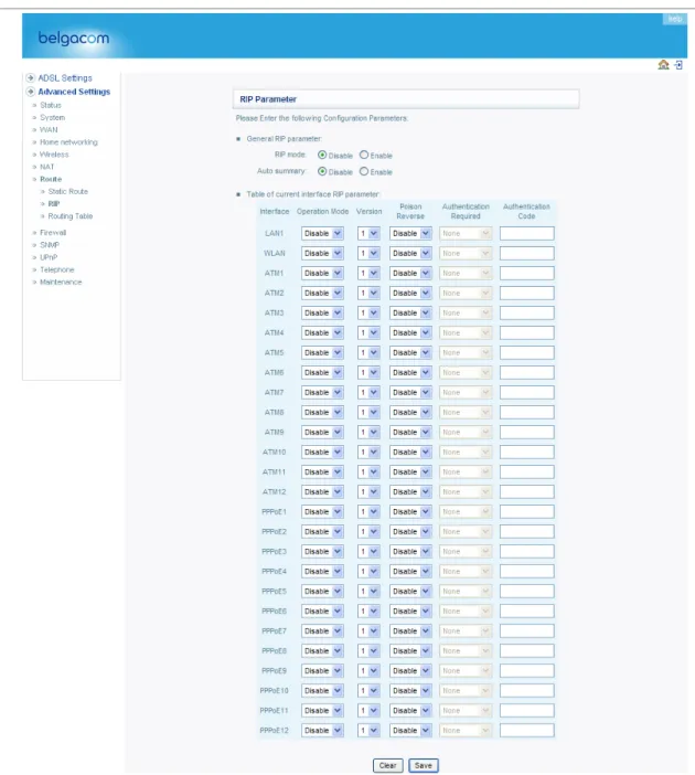
RIP Parameter
The device supports RIP v1 and v2 to dynamically exchange routing information with adjacent routers.
Parameter Description
General RIP Parameters
RIP mode Globally enables or disables RIP.
Auto summary If Auto summary is disabled, then RIP packets will include sub-network information from all subnetworks connected to the ADLS Router. If enabled, this sub-network information will be summarized to one piece of information covering all sub-networks.
Table of current Interface RIP parameter
Interface The WAN interface to be configured. Operation Mode Disable: RIP disabled on this interface.
Enable: RIP enabled on this interface.
not participate in sending route broadcasts.
Parameter Description
Version Sets the RIP version to use on this interface.
Poison Reverse A method for preventing loops that would cause endless retransmission of data traffic.
Authentication Required
None: No authentication.
Password: A password authentication key is included in the packet. If this does not match what is expected, the packet will be discarded. This method provides very little security as it is possible to learn the authentication key by watching RIP packets.
MD5: An algorithm that is used to verify data integrity through the creation of a 128-bit message digest from data input (which may be a message of any length) that is claimed to be as unique to that specific data as a fingerprint is to a specific individual.
Authentication Code Password or MD5 Authentication key.
RIP sends routing-update messages at regular intervals and when the network topology changes. When a router receives a routing update that includes changes to an entry, it updates its routing table to reflect the new route. RIP routers maintain only the best route to a destination. After updating its routing table, the router immediately begins transmitting routing updates to inform other network routers of the change.
Routing Table
Parameter Description
Flags Indicates the route status:
C = Direct connection on the same subnet. S = Static route.
R = RIP (Routing Information Protocol) assigned route. I = ICMP (Internet Control Message Protocol) Redirect route. Network Destination IP address. Address
Netmask The subnetwork associated with the destination.
This is a template that identifies the address bits in the destination address used for routing to specific subnets. Each bit that corresponds to a “1” is part of the subnet mask number; each bit that corresponds to “0” is part of the host number.
Gateway The IP address of the router at the next hop to which frames are forwarded. Interface The local interface through which the next hop of this route is reached.
Metric When a router receives a routing update that contains a new or changed destination network entry, the router adds 1 to the metric value indicated in the update and enters the network in the routing table.
Firewall
The Belgacom b-box’s firewall enables access control of client PCs, blocks common hacker attacks, including IP Spoofing, Land Attack, Ping of Death, IP with zero length, Smurf Attack, UDP port loopback, Snork Attack, TCP null scan, and TCP SYN flooding. The firewall does not significantly affect system performance and we advise leaving it enabled to protect your network.
Note: After you check the radio button in the “Enable or disable Firewall features” field, you must
Access Control
Access Control allows users to define the outgoing traffic permitted or not-permitted through the WAN interface. In the example above, all incoming and outgoing emails are blocked. The default is to permit all outgoing traffic. (See the following page for details.)
The Belgacom b-box can also limit the access of hosts within the local area network (LAN). The MAC Filtering Table allows the Belgacom b-box to enter up to 32 MAC addresses that are not allowed access to the WAN port.
The following items are displayed on the Access Control screen:
Parameter Description
Enable Filtering Enables or disables the filtering function. Function
Normal Filtering Table Displays the IP address (or an IP address range) filtering table. Click Add PC on the Access Control screen to view the following page.
Access Control Add PC
Define the appropriate settings for client PC services (as shown above). Click “OK” to save your settings. The added PC will now appear in the Access Control page.
MAC Filter
The Belgacom b-box can also limit the access of hosts within the local area network (LAN). The MAC Filtering Table allows the Belgacom b-box to enter up to 32 MAC addresses that are allowed access to the WAN port. All other devices will be denied access.
URL Blocking
To configure the URL Blocking feature, use the table below to specify the web sites (www.somesite.com) and/or keywords you want to filter on your network.
To complete this configuration, you will need to create or modify an access rule in “Access Control” on page 4-33. To modify an existing rule, click the Edit option next to the rule you want to modify. To create a new rule, click on the Add PC option.
From the Access Control, Add PC section, check the option for “WWW with URL Blocking” in the Client PC Service table to filter out the web sites and keywords selected below, on a specific PC.
The Belgacom b-box allows the user to block access to web sites from a particular PC by entering either a full URL address or just a keyword. This feature can be used to protect children from accessing violent or pornographic web sites.
Schedule Rule
You may filter Internet access for local clients based on rules.
Each access control rule may be activated at a scheduled time. Define the schedule on the Schedule Rule page, and apply the rule on the Access Control page.
Click Add Schedule Rule.
Edit Schedule Rule
Define the appropriate settings for a schedule rule (as shown on the following screen). The rule in the screen shot above prohibits emailing from 3.00pm to 11.59pm from Monday to Thursday. Upon completion, click “OK” to save your schedule rules.
Intrusion Detection
The Belgacom b-box’s firewall inspects packets at the application layer, maintains TCP and UDP session information including timeouts and number of active sessions, and provides the ability to detect and prevent certain types of network attacks such as Denial-of-Service (DoS) attacks.
Network attacks that deny access to a network device are called DoS attacks. DoS attacks are aimed at devices and networks with a connection to the Internet. Their goal is not to steal information, but to disable a device or network so users no longer have access to network resources.
The Belgacom b-box protects against DoS attacks including: Ping of Death (Ping flood) attack, SYN flood attack, IP fragment attack (Teardrop Attack), Brute-force attack, Land Attack, IP Spoofing attack, IP with zero length, TCP null scan (Port Scan Attack), UDP port loopback, Snork Attack.
Note: The firewall does not significantly affect system performance, so
we advise enabling the prevention features to protect your network.
Parameter Defaults Description
Enable SPI
and Yes
The Intrusion Detection feature of the Telephony
Anti-DoS firewall protection
Router limits the access of incoming traffic at the WAN port. When the Stateful Packet
Inspection (SPI) feature is turned on, all incoming packets are blocked except those types marked with a check in the Stateful Packet Inspection section at the top of the screen.
Stateful Packet Inspection
This option allows you to select different application types that are using dynamic port numbers. If you wish to use Stateful Packet
Inspection (SPI) for blocking packets, click on the Yes radio button in the “Enable SPI and Anti-DoS
firewall protection” field and then check the inspection type that you need, such as Packet
Fragmentation, TCP Connection, UDP Session, FTP Service, H.323 Service, and TFTP Service. It is called a “stateful” packet inspection because it examines the contents of the packet to determine the state of the communication; i.e., it ensures that
the stated destination computer has previously requested the current communication. This is a way of ensuring that all communications are initiated by the recipient computer and are taking place only with sources that are known and trusted from previous interactions. In addition to being more rigorous in their inspection of packets, stateful inspection firewalls also close off ports until a connection to the specific port is requested. When particular types of traffic are checked, only the particular type of traffic initiated from the internal LAN will be allowed. For example, if the user only checks FTP Service in the Stateful Packet Inspection section, all incoming traffic will be blocked except for FTP connections initiated from the local LAN.
Hacker Prevention Feature
Discard Ping from WAN
Discard Prevents a ping on the router’s WAN port from being routed to the network.
Parameter Defaults Description
RIP Defect Enabled If the router does not reply to an IPX RIP request
packet, it will stay in the input queue and not be
released. Accumulated packets could cause the
input queue to fill, causing severe problems for all
protocols. Enabling this feature prevents the packets accumulating. When hackers attempt to enter your network, we can alert youby email Your E-mail Address
Enter your email address. SMTP
Server Address
Enter your SMTP server address (usually the part of the email address following the “@” sign).
POP3 Server Address
Enter your POP3 server address (usually the part of the email address following the “@” sign). User Name Enter your email account user
name.
Password Enter your email account password. Connection Policy
Fragmentation 10 secs Configures the number of seconds that a packet
half-open wait state structure remains active. When the timeout value expires, the router drops the unassembled packet, freeing that structure for use by another packet.
TCP SYN wait 30 secs Defines how long the software will wait for a TCP session to reach an established state before dropping the session.
TCP FIN wait 5 secs Specifies how long a TCP session will be managed after the firewall detects a FIN-exchange.
TCP connection 3600 secs The length of time for which a TCP session will be idle timeout (1 hour) managed if there is no activity.
UDP session idle 30 secs The length of time for which a UDP session will timeout be managed if there is no activity.
H.323 data 180 secs The length of time for which an H.323 session will channel idle be managed if there is no activity.
timeout
Parameter Defaults Description
DoS Detect Criteria
Total incomplete 300 Defines the rate of new unestablished sessions that TCP/UDP sessions will cause the software to start deleting half-open sessions HIGH sessions.
Total incomplete 250 Defines the rate of new unestablished sessions that TCP/UDP sessions will cause the software to stop deleting half-open sessions LOW sessions.
Incomplete 250 Maximum number of allowed incomplete TCP/UDP sessions TCP/UDP sessions per minute. sessions (per min.)
HIGH
Incomplete 200 Minimum number of allowed incomplete TCP/UDP sessions TCP/UDP sessions per minute. sessions (per min.)
LOW
Maximum 10 Maximum number of incomplete TCP/UDP incomplete sessions from the same host.
TCP/UDP sessions number from same host
Incomplete 300 msecs Length of time before an incomplete TCP/UDP TCP/UDP session is detected as incomplete.
sensitive time period
Maximum 30 Maximum number of half-open fragmentation half-open packets from the same host.
fragmentation packet
number from same host
Half-open 1 secs Length of time before a half-open fragmentation fragmentation session is detected as half-open.
detect sensitive time period
Flooding cracker 300 secs Length of time from detecting a flood attack to block time blocking the attack.
DMZ
If you have a client PC that cannot run an Internet application properly from behind the firewall, you can open the client up to unrestricted two-way Internet access. Enter the IP address of a DMZ (Demilitarized Zone) host on this screen. Adding a client to the DMZ may expose your local network to a variety of security risks, so only use this option as a last resort.
SNMP
Community
Use the SNMP configuration screen to display and modify parameters for the Simple Network Management Protocol (SNMP). A computer attached to the network, called a Network
Management Station (NMS), can be used to access this information. Access rights to the agent are controlled by community strings. To communicate with the Belgacom b-box, the NMS must first submit a valid community string for authentication.
Parameter Description
Community A community name authorized for management access. Access Management access is restricted to Read
or Write.
Valid Enables or disables the entry.
Trap
Parameter Description
IP Address Community
Version Traps are sent to this address when errors or specific events occur on the network. A community string (password) specified for trap management. Enter a word, something other than public or private, to prevent unauthorized individuals from reading information on your system.
Sets the trap status to disabled, or enabled with V1 or V2c.
The v2c protocol was proposed in late 1995 and includes enhancements to v1 that are
universally accepted. These include a get-bulk command to reduce network management traffic when retrieving a sequence of MIB variables, and a more elaborate set of error codes for improved reporting to a Network Management Station.
ADSL
ADSL Parameters
We recommend leaving the Operation Mode at the default Automatic setting, to automatically negotiate with the remote DSLAM.
Parameter Description
Operation Mode • Automatic
T1.413 Issue 2 G.992.1 (G.DMT) G.992.2 (G.Lite) G.992.3 (ADSL2) G.992.5 (ADSL2+)