IMPLEMENTATION OF THE ZERO-ERROR
ONE SECOND TIMING ALGORITHM FOR
MICROCONTROLLER
Feyzi AKAR, CdrAsst.Prof.
Faculty of Electrical and Electronics Engineering, Naval Academy, Tuzla, 34940, Istanbul, Turkey
[email protected] Özdemir ÇETIN
Asst.Prof.
Technical Education Faculty, Computer Systems Education,
Esentepe Campus, Serdivan, Sakarya, 54187,Turkey [email protected]
Abstract
This paper presents a novel accurate timer method that can be used for generating regular of zero-error one second period. Time functions have crucial importance in many control systems. This may manifest itself in the measurement of duration, event counting or control of an external physical event for known periods. Microcontrollers have programmable timers which can be used in many tasks, such as generating timing signals, causing interrupts to be generated at specific time intervals, measuring frequency and time intervals, and so on. Timing errors, which can be measured with microseconds in interrupt subroutine that can be, bring about irretrievable results in control applications. The objective of this research is to propose a new algorithm and implementation its application for generating zero-error one-second period with PIC Microcontrollers that uses an interrupt to carry out accurate timing-related operations inside the microcontroller.
134
M
İKRODENETLEYİCİLER İÇİN SIFIR HATALI
BİR
-
SANİYE ZAMANLAMA
ALGORİTMALARININ
GERÇEKLEŞTİRİLMESİ
Özetçe
Bu makalede düzenli olarak sıfır-hatalı bir saniye periyodu üretilmesiyle ilgili yeni bir yöntem oluşturulmaktadır. Bir çok control sisteminde zamanlama fonksiyonları kritik öneme sahiptir. Bu durum harici fiziksel olayların saydırılmasında, sayma esnasında sürenin ölçümünde ortaya çıkabilir.
Mikrodenetleyicilerbir özel kesmelerin zamanlama sinyallerinin üretilmesi, frekans ölçülmesi vb. gibi bir çok görevlerde kullanılabilen programlanabilir zamanlayıcılara sahiptirler. Zamanlama hataları control uygulamalarında kesme altprogramları ile mikrosaniyelerle ölçülebilen telafi edilemez sonuçlara neden olabilmektedir. Bu çalışmanın amacı PIC
Mikrodenetleyiciler ile sıfır hatalı zamanlama periyotlarının üretilmesinde yeni bir algoritma önermek ve gerçekleştirmektir.
Keywords:Assembly, embedding systems, timing algorithm, interrupt, PIC
Anahtar Kelimeler: Assembly, gömülü sistemler, zamanlama algortimaları, kesme, PIC
1. INTRODUCTION 1.1. Embedded Systems
Basically a microcontroller is a self-contained computer system on a single chip that includes a processor, data and program memory (RAM, ROM, EEPROM), serial and parallel input/output ports which are some way of communicating with the outside world. Microcontrollers are virtually everywhere in our modern world. About 50 percent of all microcontroller applications are found in office and house equipment, such as mobile phones, DVD Players, video cameras, toys, kitchen appliances, TVs and VCRs, phones and answering machines, automobiles and most self-contained electronic systems. It is essential for the operation of above-mentioned devices and allows an independent functionality to its user. In
this sense an MCU (Microcontroller Unit) is also called an embedded system that provides the key element in the vast range of programmed devices which are now commonplace. In most cases the presence of a small LCD screen in electronic devices indicates that this device has got also an MCU.
Today many different microcontrollers are available in control applications. In this paper we shall be looking at “an accurate timer” programming and system design for the PIC (programmable interface controller) series of microcontrollers manufactured by Microchip Technology Inc.
1.2 Timer Modules
Timers are the most important parts of any microcontroller, which are available in all mid-range devices. Microcontrollers have programmable timers which can be used in many tasks, such as generating timing signals, causing interrupts to be generated at specific time intervals, measuring frequency and time intervals, and so on. Time functions have crucial importance in many control systems. This may manifest itself in the measurement of duration, event counting or control of an external physical event for known periods. Where time is of the essence these functions are often best implemented by using hardware counters to time events.
A timer can be 8 bits or 16 bits wide. Data can be loaded into a timer under program control, and the timer can be stopped or started by program control. Most timers can be configured to generate an interrupt when they reach a certain count (usually when they overflow). The user program can use an interrupt to carry out accurate timing-related operations inside the microcontroller [1].
A timer is basically a counter that is driven from either an external clock pulse or the microcontroller’s internal oscillator.
136
The TIMER0 module shown in Fig.1 is present in all PICs of this family. It has the following features:[2]
8-bit timer/counter Readable and writable
8-bit programmable Prescaler External or internal clock source
Interrupt generation on overflow (from FFh to 00h) Edge select for external clock
2. PROPOSED ZERO-ERROR TIMING TECHNIQUE 2.1. Design of Timing Algorithm
The formula that follows can be used to calculate the time it will take for the timer to overflow (or to generate an interrupt) given the oscillator period, the value loaded into the timer, and the Prescaler value: [3,4,5]
Overflow time = 4 TOSC Prescaler (256 – TMR0) (1.1)
Where;
Overflow time: Overflow time is in ms. TOSC : TOSC is the oscillator period
in ms.
Prescaler : Prescaler is the Prescaler value.
TMR0 : TMR0 is the value loaded into
TMR0 register.
For example, assume that we are using a 4MHz crystal, and the Prescaler is chosen as 1:8 by setting bits PS2:PS0 to 010. Also assume that the value loaded into the timer register TMR0 is decimal 100. The overflow time is then given by:
4MHz clock has a period, T = 1/f = 0.25s
using the below formula;
Overflow time = 4 TOSC Prescaler (256 – TMR0) Overflow time = 4 0.25 8 (256 – 100) = 1248s
Thus, the timer will overflow after 1.248msec, and a timer interrupt will be generated if the timer interrupt and global interrupts are enabled.
138
What we normally want is to know what value to load into the TMR0 register for a required overflow time. This can be calculated by modifying Equation (1.1) as follows:
TMR0 = 256 – (Overflow time) / (4 TOSC Prescaler) (1.2)
For example, suppose we want an interrupt to be generated after 500ms and the clock and the prescaler values are as before. The value to be loaded into the TMR0 register can be calculated using Equation (1.2) as follows:
TMR0 = 256 – (500) / (4 0.25 8) = 193.5
The closest number we can load into TMR0 register is 193.
The common application of the Timer0 module is as an instruction cycle counter in implementing delay loops. Timer0 register is also called a free running timer. There are two advantages of using free running timers over conventional delay loops: the Prescaler provides a way of slowing down the count, and the delay is independent of the number of machine cycles in the loop body. In most cases, it is easier to implement an accurate time delay using the Timer0 module than by counting instruction cycles [6]. Calculating the time is taken by each counter iteration that consists of dividing the clock speed by four. For example, a PIC is running on a 4 MHz oscillator clock increment the counter every 1 MHz. If the Prescaler is not used, the counter register is incremented at a rate of 1 µs; the timer beats at a rate of 1,000,000 times per second. If the Prescaler is set to the maximum divisor value (256) then each increment of the timer takes place at a rate of 1,000,000/256 µs, which is approximately 3.906 ms (exact value: 3.906.25ms). Since this is the slowest possible rate of the timer in a machine running at 4 MHz, it is often necessary to employ supplementary counters in order to achieve larger delays [6].
140
Overflow time = 4 TOSC Prescaler (256 – TMR0)
Where;
Overflow time: Overflow time is in ms. TOSC : TOSC is the oscillator period
in ms. 4MHz clock has a period, T = 1/f = 0.25s
Prescaler : Prescaler is the Prescaler value. (TMR0 Rate: 1:1)
TMR0 : TMR0 is the value loaded into
For example, assume that we are using a 4MHz crystal, and the Prescaler is chosen as 1:1. To achieve a 1:1 Prescaler assignment for the TMR0 register, assign the Prescaler to the Watchdog Timer (OPTION_REG <3> PSA=1) [7,8].
Also assume that the value loaded into the timer register TMR0 is 00h. The overflow time is then given by: using the below formula;
Overflow time = 4 TOSC Prescaler (256 – TMR0) Overflow time = 4 0.25 1 (256 – 0) = 256 s
Thus, the timer will overflow after 0.256 msec, and a timer interrupt will be generated if the timer interrupt and global interrupts are enabled [7,8,9].
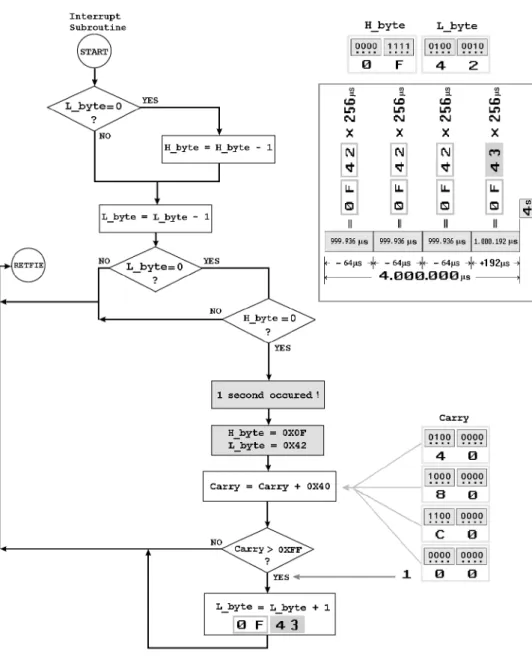
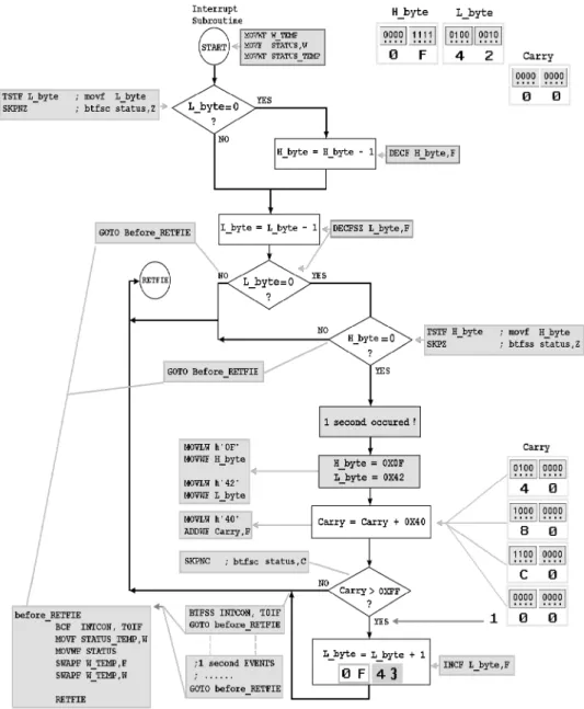
256s 0F42h =
256s 3.906 = 999.936s 256s 0F43h =
256s 3.907 = 1.000.192s
Error values of the TMR0 are zero for every four seconds in Timer0; this situation can be shown in below.
Overflow time = 4 TOSC Prescaler (256 – TMR0)
Where;
Overflow time: Overflow time is in ms. TOSC : TOSC is the oscillator period
in ms. 4MHz clock has a period, T = 1/f = 0.25s
Prescaler : Prescaler is the Prescaler value. (TMR0 Rate: 1:2)
TMR0 : TMR0 is the value loaded into
TMR0 Register. (00h)
For example, assume that we are using a 4MHz crystal, and the prescaler is chosen as 1:2 by setting bits PS2:PS0 to 000. Also assume that the value loaded into the timer register TMR0 is 00h. The overflow time is then given by:
4MHz clock has a period, T = 1/f = 0.25s
using the below formula;
Overflow time = 4 TOSC Prescaler (256 – TMR0) Overflow time = 4 0.25 2 (256 – 0) = 512s
Thus, the timer will overflow after 0.512msec, and a timer interrupt will be generated if the timer interrupt and global interrupts are enabled. To achieve a 1:2 prescaler assignment for the TMR0 register, assign the prescaler to the Timer0 (OPTION_REG <3> PSA=0).
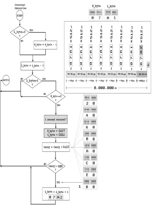
512s 07A1h =
512s 1.953 = 999.936s 512s 07A2h =
144
2.2 Implementation of One-Second-Timer Control Algorithm
This study contains a novel accurate timer method that can be used for generating regular of zero-error one-second period. Time functions have crucial importance in many control systems. This may manifest itself in the measurement of duration, event counting or control of an external physical event for known periods. Timing errors, which can be measured with microseconds in interrupt subroutine that can be, bring about irretrievable results in control applications. The objective of this research is to propose a new algorithm and implementation its application for generating zero-error one-second period with PIC Microcontrollers that uses an interrupt to carry out accurate timing-related operations inside the microcontroller.
In Fig. 2.1 and 2.3, flowchart of the one-second timer control algorithms is presented with two distinct approaches respectively. Ultimate aim is to reset the error rate at the end of the fourth and eighth second.
146
3. CONCLUSION
148
In this paper, we have proposed two new zero-error one-second timer control algorithms based on PIC micro. In this proposed algorithms, the total error rate is zero at the each end of the fourth and eighth seconds by the system, which makes this study distinctive in the literature. The objective of this research is to propose a new algorithm and implementation its application for generating zero-error one-second period with PIC Microcontrollers that uses an interrupt to carry out accurate timing-related operations inside the microcontroller.
REFERENCES
[1] Dogan Ibrahim, Advanced PIC Microcontroller Projects in C, ISBN-13: 978-0-7506-8611-2, Elsevier, 2008.
[2] PICmicro™ Mid-Range MCU Family Reference Manual, DS33023A, Microchip Technology Inc.,1997
[3]. PIC16F87XA, Data Sheet- DS39582B, Microchip Technology Inc., 2003. [4] PIC16F62X, Data Sheet- DS40300C, Microchip Technology Inc., 2003. [5] PIC16F84A, Data Sheet- DS35007B, Microchip Technology Inc., 2001. [6] Julio Sanchez, Maria P. Canton Microcontroller
Programming The Microchip PIC CRC Pres, 2007
[7] Feyzi Akar, Mustafa Yağımlı, PIC Mikrodenetleyiciler, 16F84A & 16F628A, Beta Yayınevi, 2006
[8] Feyzi Akar, Mustafa Yağımlı, PIC 16F877A Proje Tasarımı, Beta Yayınevi, 2007 [9] John Iovine, PIC Microcontroller Project Book, McGraw-Hill, 2000.
[10] Charles Kim, Embedded Computing with PIC 16F877 – Assembly Language Approach, 2006