A Low Latency Router Supporting Adaptivity for On-Chip
Interconnects
∗Jongman Kim
Dongkook Park
T. Theocharides
N. Vijaykrishnan
Chita R. Das
Department of Computer Science and Engineering
The Pennsylvania State University
University Park, PA 16802.
{jmkim, dpark, theochar, vijay, das}@cse.psu.edu
ABSTRACT
The increased deployment of System-on-Chip designs has drawn attention to the limitations of on-chip interconnects. As a potential solution to these limitations, Networks-on -Chip (NoC) have been proposed. The NoC routing algorithm significantly influences the performance and energy consumption of the chip. We propose a router architecture which utilizes adaptive routing while maintain-ing low latency. The two-stage pipelined architecture uses look ahead routing, speculative allocation, and optimal output path se-lection concurrently. The routing algorithm benefits from congestion-aware flow control, making better routing decisions. We simulate and evaluate the proposed architecture in terms of network latency and energy consumption. Our results indicate that the architecture is effective in balancing the performance and energy of NoC de-signs.
Categories and Subject Descriptors:
[B.4 I/O and Data Communications]:Interconnections(Subsystems),
[B.8:Performance and Reliability]:Performance Analysis and De-sign Aids.
General Terms:
Design, Performance.
Keywords:
Adaptive Routing, Networks-On-Chip, Interconnection Networks.
1.
INTRODUCTION
With the growing complexity of System-on-Chip (SoC) archi-tectures, the on-chip interconnects are becoming a critical bottle-neck in meeting performance and power consumption budgets of the chip design. The ICCAD 2004 Keynote Speaker [17] empha-sized the need for an interconnect centric design by illustrating that in a 65nm chip design, up to 77% of the delay is due to intercon-nects. Packet-based on chip communication networks [10, 5, 4]
∗This research was supported in part by NSF grants CCR-0093085,
CCR-0098149, CCR-0208734, CCF-0429631, EIA-0202007, and MARCO/DARPA GSRC:PAS.
Permission to make digital or hard copies of all or part of this work for personal or classroom use is granted without fee provided that copies are not made or distributed for profit or commercial advantage and that copies bear this notice and the full citation on the first page. To copy otherwise, to republish, to post on servers or to redistribute to lists, requires prior specific permission and/or a fee.
DAC 2005,June 13–17, 2005, Anaheim, California, USA
Copyright 2005 ACM 1-59593-058-2/05/0006 ...$5.00.
(a.k.a network-on-chip (NoC) designs) have been proposed to ad-dress the challenges of increasing interconnect complexity.
The design of NoC imposes several interesting challenges as compared to traditional off-chip networks. The resource limita-tions - area and power limitalimita-tions - are major constraints influenc-ing NoC designs. Early NoC designs used dimension order rout-ing, due to its simplicity and deadlock avoidance. However, tra-ditional networks enjoy complicated routing algorithms and pro-tocols, which provide adaptivity to various traffic topologies, han-dling congestion as it evolves in the network. The challenge in using adaptive routing in NoC designs, is to limit the overhead in implementing such a design.
In this work, we present a low-latency two-stage router archi-tecture suitable for NoC designs. The router archiarchi-tecture uses a speculative strategy based on lookahead information obtained from neighboring routers, in providing routing adaptation. A key aspect of the proposed design is its low latency feature that makes the lookahead information more representative than possible in many existing router architectures with higher latencies. Further, the router employs a pre-selection mechanism for the output channels that helps to reduce the complexity of the crossbar switch design.
We evaluated the proposed router architecture by using it in 2D mesh and torus NoC topologies, and performing cycle-accurate simulation of the entire NoC design using various workloads. The experimental results reveal that the proposed architecture results in lower latency than when using a deeper pipeline router. This results from the more up to date congestion information used by the pro-posed low-latency router. We also demonstrate that the adaptivity provides better performance in comparison to deterministic rout-ing for various workloads. We also evaluate our design from an energy standpoint, as we designed and laid out the router compo-nents, and obtained both dynamic and leakage energy consumption of the router. Our results indicate that for non-uniform traffic, our adaptive routing algorithm consumes less energy than dimension order routing, due to the decrease in the overall network latency.
This paper is organized as follows. First, we give a short back-ground of existing work in Section 2. We present the proposed router architecture and the algorithm in Section 3, and we evalu-ate our architecture in Section 4. Finally we conclude our paper in Section 5.
2.
RELATED WORK
The quest for high performance and energy efficient NoC ar-chitectures has been the focus of many researchers. Fine-tuning a system into maximizing system performance and minimizing en-ergy consumption includes multiple trade-offs that have to be ex-plored. As with all digital systems, energy consumption and system
performance tend to be contradictory forces in the design space of on-chip networks. Router architectures have dominated early NoC research, and the first NoC designs [5, 9] proposed the use of simplistic routers, with deterministic routing algorithms. Grad-ually researchers have explored multiple router implementations, and ongoing research such as [12, 2, 7, 3] explores implementations where pipelined router architectures utilize virtual channels and ar-bitration schemes to achieve Quality of Service (QoS) and high-bandwidth on-chip communication. Mullins, et. al. [14] propose a single stage router with a doubly speculative pipeline to minimize deterministic routing latency. Among the disadvantages however of such approach, is an increased contention probability for the cross-bar switch, given the single-stage switching. The results given in [14] do not seem to take contention into consideration. Addition-ally, emphasis on the intra-router delay does not imply adaptivity to the network congestion. As such, a better approach should com-bine both low intra-routing latency, and adaptivity to the network traffic.
Under non-uniform traffic, or application-specific (i.e. real time multimedia) traffic, deterministic routing might not be able to re-act to congestion due to network bursts, and consequently results in an increase in network delay. Adaptive routing algorithms em-ployed in traditional networks as a solution to congestion avoidance are more suitable for NoC implementations. As a result, adaptive routing algorithms have recently surfaced for NoC platforms. Such examples include thermal aware routing [18], where hotspots are avoided by using a minimal-path adaptive routing function, and a mixed-mode router architecture [11] which combines both adap-tive and deterministic modules, and employs a congestion control mechanism. Both these adaptive schemes do not use up-to-date congestion information to make the routing decision. A preferred method is to use real time congestion information about the des-tination node, and concurrently utilize adaptive routing to handle fluctuation. A disadvantage, however, that adaptive routing algo-rithms might suffer is the increased hardware complexity, and pos-sibly higher power consumption. Energy consumption is a primary design constraint, and power driven router design and power mod-els for NoC platforms, have been investigated in [19, 8]. Energy consumption depends on the number of hops a packet travels prior to reaching its destination, We believe that by reducing the overall network latency and increasing the throughput, the minor energy penalty paid when migrating from deterministic to adaptive routing is nullified by the performance of adaptive routing in non-uniform traffic. The motivation for our work, therefore, focuses on sup-porting adaptivity, while maintaining low latency and low energy consumption.
3.
PROPOSED ROUTER MODEL
The NoC latency impacts the performance of many on-chip ap-plications. Minimization of message latency by optimizing the intra-node delay and utilizing organized wiring layout with regular topologies has been targeted in NoC designs. The proposed router, designed with this objective, consists of a two-stage pipelined model with look ahead routing and speculative path selection [6, 16]. In this section, we present a customized router architecture that can support deterministic, and adaptive routing in 2-D mesh and torus on-chip networks.
3.1
Proposed Router Architecture
A typical state-of-the-art, wormhole-switched, virtual channel (VC) flow control router consists of four major modules: rout-ing control (RC), VC allocation (VA), switch allocation (SA), and switch transfer (ST). In addition, it may have an extra stage at
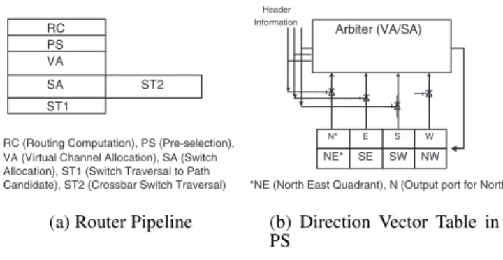
each input port for buffering and synchronization of arriving flits. Pipelined router architectures typically arrange each module as a pipeline stage. It is possible to reduce the critical path latency by reducing the pipelined stages through look-ahead routing [14]. Fig-ure 1(a) illustrates the logical modules of our two-stage pipelined router incorporating look ahead routing and speculative allocation. The first stage of the router performs look ahead routing decision for the next hop, pre-selection of an optimal channel for the in-coming packet (header), VA and SA in parallel. The actual flit transfer is essentially split in two ”stages”, the preliminary semi-switch traversal through the VC selection (ST1) and the decom-posed crossbar traversal (ST2). In contrast to the prior router ar-chitectures, the proposed model incorporates a pre-selection (PS) unit as shown in Figure 1. The PS unit uses the current switch state and network status information to decide a physical channel (PC) from among the possible paths, computed during the previ-ous stage look-ahead decision. Thus, when a header flit arrives at a router (stagei), the RC unit decides a possible set of output PCs for the next hop (i+1). The possible paths depend on the destination tag and the routing algorithm employed. Instead of using a routing table for path selection, we use a hardware control that computes a 3-bit direction vector, called Virtual Channel ID (VCID), (based on the four destination quadrants (NE, NW, SE, and SW) and four di-rections (N, E, S and W)), which can be sent along with the header, for deciding an optimal path using the PS unit in the next hop. The VA and SA are then performed concurrently for the selected output, before the the transfer of flits across the crossbar.
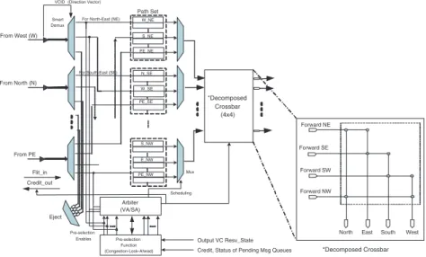
The detailed design of the router is shown in Figure 2. We de-scribe its functionality with respect to a 2-D mesh or torus. The router has five inputs, marked for convenience inputs from the four directions and one from the local PE. It has four sets of VCs, called path sets; one set for possible traversal in each of the four quad-rants; NE, SE, NW, SW. Each path set has three groups of VCs to hold flits from possible directions from the previous router.
VA
SA ST2
RC (Routing Computation), PS (Pre-selection), VA (Virtual Channel Allocation), SA (Switch Allocation), ST1 (Switch Traversal to Path Candidate), ST2 (Crossbar Switch Traversal)
PS RC
ST1
(a) Router Pipeline
NE* SE SW NW
N* E S W
Arbiter (VA/SA)
Header Information
*NE (North East Quadrant), N (Output port for North)
(b) Direction Vector Table in PS
Figure 1: The Two-Stage Pipelined Router
This grouping is customized for a 2-D interconnect. For exam-ple, a flit will traverse in the NE quadrant only if is coming from the west, south or the PE itself. Similarly, it will traverse the NW quadrant if the entry point is from south, east or the local PE. Thus, based on this grouping, we have 3VCs per PC. Note that it is pos-sible to provide more VCs per group if there is adequate on-chip buffering capacity, and the VA selects one of the VCs in a group.
The MUX in each path set selects one of the VCs for crossbar arbitration. In the mean time, the PS generates the pre-selection enable signals to the arbiter based on the credit update, and con-gestion status information of the neighboring routers. The arbiter, in turn, handles the crossbar allocation.
Another novelty of this router is that since we are using topology tailored routing, we use a4×4decomposed crossbar with half the
VCID From West (W) From North (N) From PE Path Set Smart Demux Arbiter (VA/SA) Pre-selection Function (Congestion-Look-Ahead) Pre-selection Enables Flit_in Credit_out *Decomposed Crossbar (4x4)
Credit, Status of Pending Msg Queues Output VC Resv_State W_NE
S_NE (Direction Vector)
Eject
For North-East (NE)
For South-East (SE) PE_NE N_SE S_NW W_SE PE_SE E_NW PE_NW Forward NE Forward SE Forward SW Forward NW
North East South West
*Decomposed Crossbar Mux
Scheduling
Figure 2: Proposed Router Architecture
connections of a full crossbar as shown in Figure 2. Usually a5×5 crossbar is used for 2-D networks with one of the ports assigned to the local PE. In our architecture, a flit destined for the local PE, does not traverse the crossbar. Utilizing the look-ahead routing in-formation, it is ejected after the DEMUX. Thus, the flits save two cycles at the destination node by avoiding the switch allocation and switch traversal. This provides a significant advantage for nearest-neighbor traffic, and can take advantage of NoC mapping which places frequently communicating PEs close to each other [13].
The decomposed crossbar offers two advantages for on-chip de-sign. First, it needs less silicon and second, it should consume less energy compared to a full crossbar. In addition, because of less number of connections, the output contention probability is re-duced. This, in turn, should help in reducing the mis-speculation of the VA and SA stages.
3.2
Pre-selection Function
The pre-selection function, as outlined earlier, is responsible for selecting the channel for a packet. It maintains a direction vector table for the path selection and works one cycle ahead of the flit arrival. The direction vector table, as shown in Figure 1 (b), se-lects the optimal path for each of the four quadrant path sets. As an example, if a flit is in the W NE VC, the PS decides whether it will use the N or E direction and inputs this enable signal to the arbiter. The PS logic uses the congestion look-ahead information and cross-bar status to determine the best path, and also immediately updates the credit priorities into the arbitration. The congestion look-ahead scheme provides adaptive routing decisions with the best VC (or set of VCs) and path selection from the corresponding candidates based on the congestion information of neighboring nodes.
3.3
Adaptive Routing Algorithm
An adaptive routing algorithm either needs a routing table or hardware logic to provide alternate paths. Our proposed router can support deadlock-free fully adaptive routing for 2-D mesh and torus networks using hardware logic. Note that a flit can use any minimal path in one of the four quadrants, as discussed in the router model in Section 3.1. The final selection of an optimal channel is done by the PS module. It can be easily proved that the adaptive routing is deadlock free for a 2-D mesh because the four path sets, shown in Figure 2 are not involved in cyclic dependency. Whenever two
flits from two quadrants are selected to traverse in the same direc-tion (for example a flit from NE and a flit from SE contend for an east channel), they use separate VC in the NE and SE path sets, thereby avoiding channel dependency.
For a 2-D torus network, we use an additional VC to support deterministic and fully adaptive routing similarly to other adaptive routing algorithms in torus. One of the VCs in each subset is used for crossing dimensions in ascending order, and the other VC is used for descending order, which is possible for wrap-around links in a torus. Note that prior adaptive routing schemes need at least 3 VCs per PC to support adaptivity.
Although an adaptive routing algorithm helps in achieving bet-ter performance specifically under non-uniform traffic patbet-terns, the underlying path selection function has a direct impact on perfor-mance. Most adaptive routing algorithms take little account of tem-poral traffic variation and other possible traffic interferences.
The proposed adaptive routing algorithm, utilizes look-ahead con-gestion detection for the next router’s output links using credit-based system. The PS module keeps track of credits for each neigh-boring router on the candidate paths. Neighneigh-boring routers send credits indicating congestion (VC state), with the amount of free buffer space available for each VC. In addition, time between suc-cessive transmissions to neighboring routers is kept minimal due to the low latency of our architecture, and consequently our pro-posed architecture captures congestion traffic in short spurts and reacts accordingly. This helps in capturing congestion fluctuation and picking the right channel from amongst the available candidate channels.
3.4
Contention Probabilities
To illustrate the benefits of our decomposed crossbar architec-ture, we compare the contention probabilities of a full crossbar versus our decomposed crossbar design. We derive the contention probability as a function of the offered loadλ, whereλis the prob-ability that a flit arrives at an arbitrary time slot for each input port [15], for a generic (NxN) full crossbar and an (N-1xN-1) decom-posed crossbar, assuming uniform distribution. Letλf,λP Edenote
load directed to an output port and ejection channel respectively. LetPsbe the probability that a port is busy serving a request. Let
Qn be the probability that an input port has n flits for a specific
time Markov-chain (DTMC) as follows:
Q0= 1−λPf
s, Q0P E= 1−
λP E
Ps
The contention probabilities, Pcon f ull for the full crossbar and
Pcon decthe decomposed crossbar, can be formulated as:
Full Crossbar: Pcon f ull= NX−1 j=2 1 j „ N−1 j « (1−Q0)jQN−1−j 0 Q0P E + NX−1 j=2 1 j „ N−1 j−1 « (1−Q0)j−1QN−j 0 (1−Q0P E) Decomposed Crossbar: Pcon dec= N−1 2 X j=2 1 j „ N−1 2 j « (1−Q0)jQN2−1−j 0
The contention probability is shown in Figure 3. It is evident that the decomposed crossbar outperforms the full crossbar. The tree structure of the decomposed crossbar (see Figure 2) provides flits with pre-selected path sets towards the destination, thus reducing contention. 0.1 0.2 0.3 0.4 0.5 0.6 0.7 0.8 0.9 0 0.1 0.2 0.3 0.4 0.5 0.6 0.7 0.8 0.9 1 Contention Probability
(λf) Offered Load per Input Port for An Output Port
Full Crossbar Decomposed Crossbar
Figure 3: Comparison of Contention Probability
4.
PERFORMANCE EVALUATION
In this section, we present simulation-based performance eval-uation of our architecture in terms of network latency and energy consumption, under various traffic patterns. We describe our exper-imental methodology, and detail the procedure followed in evalua-tion of our proposed architecture.
4.1
NoC Simulator
To evaluate our architecture, we have developed an architectural level cycle-accurate NoC simulator using C, and we used simula-tion models for various traffic patterns. The simulator inputs are parameterizable allowing us to specify parameters such as network size and topology, routing algorithm, the number of VCs per PC, buffer depth, PE injection rate, flit size, and number of flits per packet. Our simulator breaks down the router architecture into individual components, modeling each component separately and combining the models in unison to model the entire router and subsequently the entire network architecture. We measure net-work latency from the time a packet is created to the netnet-work in-terface of the PE, to the time its last flit arrives at the destination
PE, including network queuing time. We assume that link prop-agation happens within a single clock cycle. In addition to the network-specific parameters, our simulator accepts hardware pa-rameters such as power consumption (leakage and dynamic) and clock period for each component, and utilizes these parameters to provide results regarding the network energy consumption.
4.2
Energy Estimation
Energy consumption for on-chip networks consumes a large chunk of the total chip energy. While no absolute numbers are given, re-searchers [19] estimate the NoC energy consumption to approx-imately 45% of the total chip power. The generic estimation in [19] relates the energy consumption for each packet to the num-ber of hop traversals per flit per packet, times the energy consumed for each flit per router. We took this estimation a step further, de-composing the router into individual components which we laid out in 70nm technology, using a power supply voltage of 1V, and 200MHz clock frequency. We used the Berkeley Predictive Tech-nology model [1], and measured the average dynamic power using 50% switching activity on the inputs. Additionally, we measured the leakage power of each component when no input activity is recorded. We imported these values into our architectural level cycle-accurate NoC simulator and simulated all individual com-ponents in unison to estimate both dynamic and leakage power in routing a flit. Doing so we were able to identify the individual utilization rates of each component, thus accurately modeling the leakage and dynamic power consumption.
A particular detail which we emphasized was to distinguish be-tween each flit type (header, data, tail) so as to correctly model the power consumed by each flit type. For instance, a header flit will be accessed by all components, where as a data flit will simply stay in the buffer until propagated to the output port.
4.3
Experimental Setup
We evaluated our architecture using two 8x8 networks, one us-ing 2D torus and the other usus-ing 2D mesh topologies. We use 4 flits per packet and wormhole routing, with 4-flit deep buffers per VC. We use 3 VCs per PC for 2D mesh and 6VCs per PC for 2D torus (as required by our algorithm). Every simulation initiates a warm-up phase of 20,000 packets. Thereafter, we inject 1,200,000 packets and simulate our architecture until all the packets are re-ceived at the destination nodes. We log the simulation results and gather network performance metrics based on our simulations for various traffic patterns. For packet injection rates, we used three workload traces: self similar web traffic, uniform and MPEG-2 video multimedia traces. We simulated each trace using four dif-ferent traffic permutations: normal-random, transpose, tornado and bit-complement [6].
4.4
Simulation Results
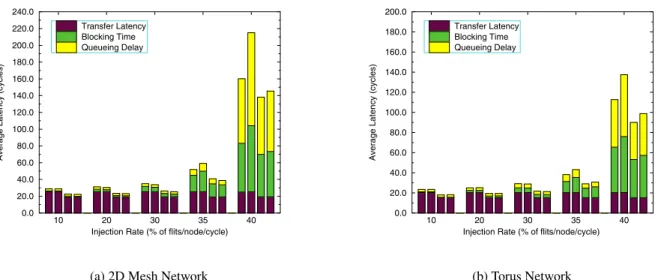
First we compare our proposed 2-stage router architecture to a 3-stage pipelined router, in order to evaluate the average network la-tency. In the 3-stage router, we implement both a dimension-order (DOR) algorithm, as well as our adaptive routing algorithm. We separate the crossbar arbitration from the routing decision stage, resulting in three stages in the router pipeline when using our adap-tive algorithm. A direct effect of this is a full crossbar switch in-stead of the decomposed crossbar our 2-stage architecture employs. We compare both routers (2-stage vs. 3-stage) using both DOR and our adaptive algorithm, and show the results in Figure 6. We par-tition the average latency in three parts: contention free transfer latency, blocking time, and queuing delay in source node. In both zero load latency, and congestion avoidance, the 2-stage router
per-forms better than the 3 stage. Figure 6 shows also the impact of adaptivity, indicating poor performance when compared to DOR under uniform random traffic. Spatial traffic evenness benefits load balancing in DOR, even if we improve adaptivity. In the presence of non-uniform traffic however, the adaptive algorithm outperforms the DOR algorithm as shown in Figure 7 for transpose (TP), self-similar(SS) and Multimedia(MM) traffic patterns. As bursty traffic is more representative of a practical on-chip communication envi-ronment, we expect our adaptive algorithm to be very useful.
An additional NoC property is spatial locality. PEs that com-municate often with each other, are usually placed in proximity to each other. In our architecture, when a packet arrives its destina-tion router, instead of traversing the crossbar to the PE, the VC selection mechanism ejects the packet into the PE immediately, by-passing the router traversal as shown in Figure 4. We also show a 3-stage router without the bypass modification in Figure 4, to illus-trate the difference. Even though in Figure 4 we assume no block-ing inside the router, as the injection rate increases, the blockblock-ing latency inside the router increases as well and the bypassing tech-nique results in significant benefits. We simulated the 2-stage and 3-stage router architectures for nearest-neighbor traffic in order to investigate the latency, which we show in Figure 5, illustrating that early ejection and intra-router latency reduction jointly decrease the overall network latency. The increased hardware complexity in im-plementing the adaptive routing algorithm results in a higher power consumption than when implementing the simpler, DOR algorithm. However, the latency reduction when using adaptive algorithm for non-uniform, more practical traffic environments, more than com-pensates for this power increase, reducing the overall energy. Fig-ure 8(a)shows the energy consumption per packet for uniform and transpose traffic, when comparing adaptive routing vs. DOR. In Figure 8(b), we also see that adaptive routing is beneficial when we consider the Energy-Delay Product for non-uniform traffic.
5.
CONCLUSIONS
We present a low-latency router architecture suitable for on-chip networks which utilizes an adaptive routing algorithm. The archi-tecture uses a novel path selection scheme resulting in a 2-stage switching operation with a decomposed crossbar switch. We eval-uate our architecture using various traffic patterns, and we show that under non-uniform traffic our architecture reduces the overall network latency by a significant factor. Due to the low latency of our architecture, congestion information about each router’s neigh-boring routers is swiftly updated, resulting in almost real-time up-dates. We also show that the energy consumption when using adap-tive routing is also reduced due to the reduction in the network la-tency. Results also show a better performance in the presence of
PE PE Router Traversal (2cycles) Packet Injection (1cycle+Tq) Bypass Link Link Traversal (1cycle) Packet Ejection PE Router Traversal (3cycles) Router Link Traversal (1cycle) Packet Ejection Router Traversal (3cycles) Router Router Packet Injection (1cycle+Tq) Normal Ejection Router Tq : Queueing Delay 2 stage bypass 3 stage non-bypass PE
Figure 4: Latency Analysis of Nearest-Neighbor Traffic
5 10 15 20 25 30 35 40 6 7 8 9 10 11 12 13
Injection Rate (% flits/node/cycle)
Average Latency (cycle)
Decomposed CB(2stage) Full CB (3stage)
Figure 5: Comparison of Nearest-Neighbor Traffic
nearest-neighbor traffic, a particular benefit for NoC designs which emphasize spatial locality. In the future we are planning to explore architectural optimizations in reducing the latency to a single stage thus obtaining better congestion information, and introduce more features in our adaptive algorithm implementation. In particular, we can expand the lookahead information for the destination router from VC state only, to include the link state and other parameters such as hotspots and permanent faults in the links and routers in order to provide hotspot avoidance and fault tolerance.
6.
REFERENCES
[1] Berkeley predictive technology model. http://www-device.eecs.berkeley.edu/ ptm/.
[2] The nostrum backbone project. http://www.imit.kth.se/info/FOFU/Nostrum/. [3] Stanford-bologna netchip project.
http://akebono.stanford.edu/users/nanni/research/net/netchip/.
[4] L. Benini and G. D. Micheli. Networks on Chips: A New SoC Paradigm.IEEE Computer, 35(1):70–78, 2002.
[5] W. J. Dally and B. Towles. Route Packets, Not Wires: On-Chip Interconnection Networks. InProceedings of the 38th Design Automation Conference, June 2001.
[6] W. J. Dally and B. Towles.Principles and Practices of Interconnection Networks. Morgan Kaufmann, 2003.
[7] J. Dielissen and et. al. Concepts and implementation of the Philips network-on-chip. InIP-Based SOC Design, Nov. 2003.
[8] N. Eisley and L.-S. Peh. High-level power analysis for on-chip networks. In
Proceedings of CASES, pages 104–115. ACM Press, 2004.
[9] P. Guerrier and A. Greiner. A generic architecture for on-chip packet-switched interconnections. InProc. of DATE, pages 250–256. ACM Press, 2000. [10] M. Horowitz, R. Ho, and K. Mai. The future of wires. InProc. of SRC
Conference, 1999.
[11] J. Hu and R. Marculescu. DyAD - Smart Routing for Networks-on-Chip. InIn Proceedings of the 41’st ACM/IEEE DAC, 2004.
[12] A. Jalabert, S. Murali, L. Benini, and G. D. Micheli. xpipes compiler: a tool for instantiating application specific networks on chip. InProc. of DATE, pages 884–889, 2004.
[13] R. M. Jingcao Hu. Energy-aware mapping for tile-based noc architectures under performance constraints. InProc. of ASPDAC, January 2003.
[14] R. Mullins and et. al. Low-latency virtual-channel routers for on-chip networks. InProc. of the 31st ISCA, page 188. IEEE Computer Society, 2004.
[15] S. Y. Nam and D. K. Sung. Decomposed crossbar switches with multiple input and output buffers. InProc. of IEEE GLOBECOM, 2001.
[16] L.-S. Peh and W. J. Dally. A Delay Model and Speculative Architecture for Pipelined Routers. InProceedings of the 7th International Symposium on High-Performance Computer Architecture, 2001.
[17] P. Rickert. Problems or opportunities? beyond the 90nm frontier, 2004. ICCAD - Keynote Address.
[18] L. Shang, L.-S. Peh, A. Kumar, and N. K. Jha. Thermal Modeling, Characterization and Management of On-Chip Networks. InProc. of the 37th MICRO, 2004.
[19] H.-S. Wang, L.-S. Peh, and S. Malik. Power-Driven Design of Router Microarchitectures in On-Chip Networks. InProceedings of the 36th MICRO, November 2003.
10 20 30 35 40 Injection Rate (% of flits/node/cycle) 0.0 20.0 40.0 60.0 80.0 100.0 120.0 140.0 160.0 180.0 200.0 220.0 240.0
Average Latency (cycles)
Transfer Latency Blocking Time Queueing Delay
(a) 2D Mesh Network
10 20 30 35 40
Injection Rate (% of flits/node/cycle) 0.0 20.0 40.0 60.0 80.0 100.0 120.0 140.0 160.0 180.0 200.0
Average Latency (cycles)
Transfer Latency Blocking Time Queueing Delay
(b) Torus Network
Figure 6: Comparison of 2-stage vs. 3-stage routers utilizing both DOR and adaptive routing algorithms. [For each injection rate, from left to right, columns correspond as follows: 3-Stage DOR, 3-Stage Adaptive, 2-Stage DOR, 2-Stage Adaptive]
5 10 15 20 25 30 35 40 0 20 40 60 80 100 120 140 160 180 200
Injection Rate (% flits/node/cycle)
Average Latency (cycle)
DOR(TP) DOR(SS) DOR(MM) Adaptive(TP) Adaptive(SS) Adaptive(MM)
(a) 2D Mesh Network
5 10 15 20 25 30 35 40 0 20 40 60 80 100 120 140 160 180 200
Injection Rate (% flits/node/cycle)
Average Latency (cycle)
DOR(TP) DOR(SS) DOR(MM) Adaptive(TP) Adaptive(SS) Adaptive(MM) (b) Torus Network
Figure 7: Performance Comparison under Non Uniform Traffic
10 20 30 40 0 0.5 1 1.5 2
Injection Rate (% flits/node/cycle)
Energy Per Packet (pJ)
DOR−UR Adaptive−UR DOR−TP Adaptive−TP
(a) Energy Consumption in Uniform and Transpose Traffic Patterns UR TP SS MM 0 50 100 150 200 Traffic Pattern
Energy Delay Product (pJ x cycle)
DOR Adaptive
(b) Energy Delay Product