PRODUCT OVERVIEW
SCHEDA TECNICA - TECHNICAL SHEET
Tel. +39 0432 747911 - Fax +39 0432 758444 www.friulsider.com - [email protected] Assistenza tec. per Italia: Tel. 0432 747906
FM-ISOMAXFissaggio con chiodo in acciaio per sistemi a cappotto ETICS / Fixing with steel nail for ETICS thermal insulation system Pag. 1/2 Rev: 02
Friulsider S.p.A si riserva il diritto di apportare modifiche senza preavviso / Friulsider reserves the right to make modifications without prior notice.
DATI TECNICI - TECHNICAL DATA
tfix = spessore max fissabile / fixture thickness do = diametro foro / hole diameter
h1 = profondità minima foro / minimum hole depth
hnom = profondità minima di posa / nominal embedment depth hmin = spessore minimo supporto / minimum support thickness d = diametro chiodo / nail diameter
dr = diametro testa / head diameter L = lunghezza ancorante / anchor length Lc = lunghezza chiodo / nail length
tipo - type do x L tfix mm h1 [mm] hnom [mm] hmin [mm] d [mm] Lc [mm] dr [mm] Cod. min max Ø8x100 25 45 70 55 100 5 100 60 61925008100 Ø8x120 45 65 115 61925008120 Ø8x140 65 85 135 61925008140 Ø8x160 85 105 155 61925008160 Ø8x180 105 125 175 61925008180 Ø8x200 125 145 195 61925008200 Ø8x220 145 165 215 61925008220 Ø8x260 180 205 260 61925008260 Ø8x300 220 245 300 61925008300 Ø8x360 280 305 360 61925008360 Ø8x400* 320 345 400* 61925008400*
* Misure non certificate CE - Not covered by CE certification
Rondella per pannelli morbidi
Washer for soft panels
Ø
[mm] Cod.
100 61925000100
SUPPORTI – BASE MATERIALS
idoneo / suitable applications parzialmente indicato / partially suitable applications calcestruzzo / concrete mattone pieno / solid brickmattone semipieno / honeycomb brick mattone forato / cell like clay brick
blocco forato Poroton / light weight honeycomb brick blocco forato cemento / hollow dense aggregate block blocco forato Leca / hollow light aggregate block cemento cellulare / aerated concrete
SCHEDA TECNICA - TECHNICAL SHEET
Tel. +39 0432 747911 - Fax +39 0432 758444 www.friulsider.com - [email protected] Assistenza tec. per Italia: Tel. 0432 747906
FM-ISOMAXFissaggio con chiodo in acciaio per sistemi a cappotto ETICS / Fixing with steel nail for ETICS thermal insulation system Pag. 2/2 Rev: 02
Friulsider S.p.A si riserva il diritto di apportare modifiche senza preavviso / Friulsider reserves the right to make modifications without prior notice.
INSTALLAZIONE - INSTALLATION
Temperatura di posa / Installation temperature: 0 / +40 °C
Temperatura di esercizio / Working temperature: -40 / +30 °C (max +70 °C breve periodo / for short period)
Trasmittanza termica/ Point thermal trasmittance:
tfix=45÷300mm - Technical Report TR025)
Calcestruzzo/Concrete Bimattone doppio UNI / Double brick UNI
= 0.005 [W/K]
= 0.004 [W/K] Non sono consigliate applicazioni permanenti con carichi sospesi oltre i 40°C utilizzando ancoranti plastici
The use of plastic anchors is not recommended for permanent suspended loading applications above 40°C.
CARATTERISTICHE ANCORANTE - PRODUCT FEATURES
Tipo Type Materiale Material Tassello Plug polipropilene polypropylene Chiodo Nail
acciaio con testa in polipropilene steel with polypropylene head
Rondella
Washer
polipropilene polypropylene
CARICHI di TRAZIONE di PROGETTO
(1)e AMMISSIBILI
(2)DESIGN
(1)and RECOMMENDED
(2)TENSILE LOADS
Tipo tasselloAnchor type Ø8
Profondità minima di posa
Nominal embedment depth hnom [mm] 55
Calcestruzzo C20/25 Concrete C20/25 Nrd [kN] 0,20 Ncons [kN] 0,13 Mattone pieno Solid brick EN771-1 fb >= 28,2 MPa Nrd [kN] 0,15 Ncons [kN] 0,10
Bimattone doppio UNI
Hollow clay brick double UNI EN771-1 fb >= 12,4 MPa
Nrd [kN] 0,15
Ncons [kN] 0,10
1kN = 100 kgf
(1)
I carichi di progetto Nrd derivano dai carichi caratteristici riportati sulla certificazione ETA-08/0094 per ETICS ETAG014 e sono comprensivi del
coefficiente parziale di sicurezza ym=2,0. / The design loads Nrd derive from the characteristic loads on the ETA-08/0094 certification for ETICS ETAG014 and are inclusive of the partial safety factor ym=2,0.
(2) I carichi ammissibili N
cons derivano dai carichi caratteristici riportati sulla certificazione ETA-08/0094 per ETICS ETAG014 e sono comprensivi dei
coefficienti parziali di sicurezza yf =1.5 and ym =2,0. Escludere la percussione nella fase di foratura su mattoni forati. Tenere conto dell’eventuale
presenza di intonaco non portante, che va compreso nello spessore fissabile tfix. / The recommended loads Ncons derive from the characteristic loads on the ETA-08/0094 certification for ETICS ETAG014 and are inclusive of the partial safety factors yf =1.5 and ym =2,0. Avoid rotary percussion when drilling into hollow brick. In presence of plaster (non-load equalizing layer), the thickness must be added to that of the insulation tfix.
In assenza di marcatura CE, i carichi consigliati derivano da prove eseguite presso il laboratorio Friulsider nel rispetto delle norme di riferimento. I valori di carico riportati hanno valore solo se l'installazione è stata eseguita correttamente. Il progettista è responsabile del dimensionamento e del numero degli ancoraggi. In the absence of CE markings, the recommended loads derive from tests carried out in the Friulsider laboratory in accordance with the appropriate standards. The load values are only valid if the installation has been carried out correctly. The design engineer is responsible for the designing and calculation of the fixing.
ETA-08/0094
Categoria d’uso A-B-C Use category A-B-C
Evropsk a org anizacij a za tehnična sog lasj a
European Org anisation f or T echnical Approvals
Slovenije
Slovenian National Building and Civil Engineering Institute
Dimičeva 12, 1000 Ljubljana, Slovenija Tel.: +386 (0)1-280 42 50 Fax: +386 (0)1-436 74 49 e-mail: [email protected] http://www.zag.si Ermächtigt u n d n o t i f i z i e r t g em äß A rt i k el 1 0 de r Richtlinie des Rates vom 21. Dezember 1988 zur An-gleichung der Rechts- und Verwalt ung svors chrift en d e r M i t g l i e d s t a a t e n
üb er B aup rod uk te (89/106/EWG)
član EOTA
European Technical Approval
ETA-08/0094
[English translation prepared by ZAG – Original version in Slovenian language]
Komercialno ime
Trade name FM-ISOMAX
Imetnik soglasja
Holder of approval
Friulsider S.p.A. via Trieste 1
33048 San Giovanni al Natisone (UD) Italy
Tip gradbenega proizvoda in njegova predvidena uporaba
Zabito plastično sidro za pritrjevanje toplotno izlolacijskih sistemov z ometi na podlagi iz betona in opečnih votlakov Generic type and use
of construction product
Nailed-in plastic anchor for fixing of external thermal insulation composite systems with rendering on concrete and hollow masonry
Veljavnost od Validity from do to 02.11.2010 16.07.2015 Proizvodni obrat Manufacturing plant Friulsider S.p.A. Manufacturing plant n.1 Slovenia
To Evropsko tehnično soglasjevsebuje
This European Technical Approval contains:
15 strani vključno s 5 prilogami, ki so sestavni del tega soglasja
15 pages including 5 annexes, which form an integral part of the document
I
LEGAL BASES AND GENERAL CONDITIONS
1. This European Technical Approval is issued by the Slovenian National Building and Civil
Engineering Institute (ZAG) in accordance with:
− Council Directive 89/106/EEC of 21 December 1988 on the approximation of laws,
regulations and administrative provisions of Member States relating to construction
products1, modified by the Council Directive 93/68/EEC2 and regulation (EC) No1882/2003
of the European Parliament and of the Council3;
− Zakon o gradbenih proizvodih – ZGPro (Ur. List, št. 52/00 in 110/02) “Construction
Product Act – ZGPro (OG RS No 52/00 and 110/02)”,
− Common Procedural Rules for Requesting, Preparing and the Granting of European
Technical Approvals set out in the Annex of Commission Decision 94/23/EC4;
− Guideline for European Technical Approval of “Plastic Anchors for Fixing of External
Thermal Insulation Composite Systems with Rendering”, ETAG 014, edition November 2001.
2. The Slovenian National Building and Civil Engineering Institute (ZAG) is authorised to
check whether the provisions of this European Technical Approval are met. Checking may take place in the manufacturing plant. Nevertheless, the responsibility for the conformity of the products with the European Technical Approval and for their fitness for the intended use remains with the holder of the European Technical Approval.
3. This European Technical Approval is not to be transferred to manufacturers or agents of
manufacturer other than those indicated on page 1; or manufacturing plants other than those indicated on page 1 of this European Technical Approval.
4. This European Technical Approval may be withdrawn by the Slovenian National Building
and Civil Engineering Institute (ZAG), in particular pursuant to information by the Commission according to Article 5 (1) of the Council Directive 89/106/EEC.
5. Reproduction of this European Technical Approval including transmission by electronic
means shall be in full. However, partial reproduction can be made with the written consent of the Slovenian National Building and Civil Engineering Institute (ZAG). In this case partial reproduction has to be designated as such. Texts and drawings of advertising brochures shall not contradict or misuse the European Technical Approval.
6. The European Technical Approval is issued by the approval body in its official language.
This version corresponds fully to the version circulated within EOTA. Translations into other languages have to be designated as such.
1
Official Journal of the European Communities No L 40, 11.2.1989, p.12 2
Official Journal of the European Communities No L 220, 30.8.1993, p.1 3
Official Journal of the European Union No L 284, 31.10.2003, p.1 4
II
SPECIFIC CONDITIONS OF THE EUROPEAN TECHNICAL
APPROVAL
1 Definition of product and intended use
1.1 Definition of product
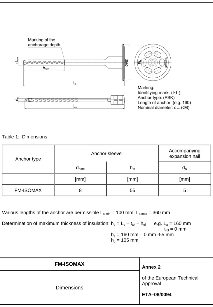
The FM-ISOMAX is a nailed-in anchor which consists of a plastic part with a plate made of polypropylene and an accompanying specific nail of galvanised steel. The head of a nail has an additional plastic coating.
The anchor is installed in drilled hole by hammering in the expansion nail. The expansion of the anchor applies the anchorage.
The installed anchor is shown in Annex 1.
1.2 Intended use
The anchor is intended to be used for anchorages for which requirements for safety in use in the sense of the Essential Requirement 4 of Council Directive 89/106/EEC shall be fulfilled and failure of anchorages made with these products cause low risk to human life. The anchor is to be used only as multiple fixing for the anchorage of bonded thermal insulation composite systems (ETICS) according to ETAG 004 in concrete and masonry. The base material shall be of reinforced or unreinforced normal weight concrete of strength classes C 16/20 at minimum and C50/60 at maximum according to SIST EN 206-1:2003 or of masonry walls made of clay bricks according to the Table 4 in Annex 4. The anchor may only be used for transmission of wind suction loads and shall not be used for the transmission of dead loads of the thermal insulation composite system. The dead loads have to be transmitted by the adhesion of the thermal insulation composite system.
The FM-ISOMAX may be used with the accompanying specific nail made of galvanised steel.
The provisions made in this European Technical Approval are based on an assumed working life of the anchor of 25 years. The indications given on the working life cannot be interpreted as a guarantee given by the manufacturer, but are to be regarded only as a means for choosing the right products in relation to the expected economically reasonable working life of the works.
2 Characteristics of product and methods of verification
2.1 Characteristics of product
The anchor corresponds to the drawings and information given in Annex 2 and 3. The characteristic material values, dimensions and tolerances of the anchor not indicated in these Annexes shall correspond to the respective values laid down in the technical
documentation5 of this European Technical Approval. The characteristic anchor values for the design of anchorage are given in Annex 4 and 5.
Each anchor is to be marked with the identifying mark of the manufacturer, the type, length and the diameter of the anchor. The minimum anchorage depth shall be marked. The anchor shall only be packaged and supplied as a complete unit.
2.2 Methods of verification
The assessment of fitness of the anchor for the intended use in relation to the requirements for safety in use in the sense of the Essential Requirement 4 has been made in accordance with
- the Guideline for European Technical Approval of “Plastic Anchors for Fixing of
External Thermal Insulation Composite Systems with Rendering” (ETAG 014), based on the use categories A and C and
- the EOTA Technical Report TR 025 “Determination of point thermal transmittance of
plastic anchors for the anchorage of external thermal insulation composite systems (ETICS).
In addition to the specific clauses relating to dangerous substances contained in this European Technical Approval, there may be other requirements applicable to the products falling within its scope (e.g. transposed European legislation and national laws, regulations and administrative provisions), In order to meet the provisions of the EU Construction Products Directive, these requirements need also to be complied with, when they apply.
3 Evaluation and attestation of conformity and CE marking
3.1 System of attestation of conformity
According to the decision 97/463/EC of the European Commission6 the system 2+ of
attestation of conformity applies.
This system of attestation of conformity is defined as follows:
System 2+: Declaration of conformity of the product by the manufacturer on the basis of: a) tasks for the manufacturer:
(1) initial type-testing of the product; (2) factory production control;
(3) testing of samples taken at the factory by the manufacturer in accordance with a control plan.
5
The technical documentation of this European Technical Approval is deposited at the Slovenian National Building and Civil Engineering Institute (ZAG) and, as far as relevant for the tasks of the approved bodies involved in the attestation of conformity procedure, is handed over the approved bodies.
6
b) tasks for the approved body:
(4) certification of factory production control on the basis of: - initial inspection of factory and of factory production control;
- continuous surveillance, assessment and approval of factory production control.
3.2 Responsibilities
3.2.1 Tasks of the manufacturer
3.2.1.1 Factory production control
The manufacturer shall exercise permanent internal control of production. All the elements, requirements and provisions adopted by the manufacturer are documented in a systematic manner in the form of written policies and procedures, including records of results performed. This production control system ensures that the product is in conformity with the European technical approval.
The manufacturer may only use raw materials stated in the technical documentation of this European technical approval. The incoming raw materials shall be subject to controls and tests by the manufacturer before acceptance. Check of incoming materials shall include control of the inspection documents presented by the manufacturer of the raw materials (comparison with nominal values) by verifying dimensions and determine the material properties.
The manufactured components of the anchor shall be subjected to the following tests:
− Steel nail
• Dimensions (diameter, lengths),
• Material property (ultimate strength),
• Check of coating (electro-galvanisation).
− Plastic sleeve
• Shape,
• Dimensions (diameter, lengths),
• Markings,
• Properties of polypropylene granules (density, melt mass-flow rate (MFR),
DSC-curve),
• Documentation of adjusting data of injection moulding machine.
− Visual control of correct assemblage and of completeness of the anchor.
The factory production control shall be in accordance with the “Control Plan of 16.07.2010 relating to the European technical approval ETA–05/0148 issued on 16.07.2010” which is part of the technical documentation of this European technical approval. The “Control Plan” is laid down in the context of the factory production control system operated by the manufacturer and deposited at the Slovenian National Building and Civil Engineering Institute (ZAG).
The results of factory production control shall be recorded and evaluated in accordance with the provisions of the “Control Plan”.
3.2.1.2 Other tasks of the manufacturer
The manufacturer shall, on the basis of a contract, involve a body which is approved for the tasks referred to in a section 3.1 in the field of FM - ISOMAX in order to undertake the actions laid down in section 3.3. For this purpose the “Control Plan” referred to in sections 3.2.1.1 and 3.2.2 shall be handed over by the manufacturer to the approved body or bodies involved.
The manufacturer shall make a declaration of conformity, stating that the construction product is in conformity with the provisions of the European technical approval ETA-08/0094 issued on 02.11.2010.
3.2.2 Tasks of approved bodies
The approved body shall perform the:
- initial inspection of factory and of factory production control,
- continuous surveillance, assessment and approval of factory production control,
in accordance with the provisions laid down in the “Control plan of 16.07.2010, relating to the European technical approval ETA–05/0148 issued on 16.07.2010”.
The approved body shall retain the essential points of its actions referred to above and state the results obtained and conclusions drawn in a written report.
The approved certification body involved by the manufacturer shall issue an EC certificate of conformity of the factory production control stating the conformity with the provisions of this European technical approval.
In cases where the provisions of the European technical approval and its “Control Plan” are no longer fulfilled the certification body shall withdraw the certificate of conformity and inform the Slovenian National Building and Civil Engineering Institute (ZAG) without delay.
3.3 CE-Marking
The CE marking shall be affixed on each packaging of anchors. The symbol “CE” shall be followed by the identification number of the approved certification body and be accompanied by the following additional information:
− the name and address of the manufacturer,
− the last two digits of the year in which the CE-marking was affixed,
− the number of the EC certificate for the factory production control,
− number of the European technical approval,
− the number of the guideline for European technical approval,
− the identification number of the certification body,
− the name or identifying mark of the manufacturer and manufacturing plant,
− size of the plastic anchor,
Example of CE marking and accompanying information for FM-ISOMAX, with La =
160 mm.
1234
“CE”-symbol
Identification number of approved certification body
Friulsider S.p.A. via Trieste 1 33048 San Giovanni al Natisone (UD) Italy 10 1234-CPD-0321
Name and the address of the manufacturer (legal entity responsible for the manufacturer)
Two last digits of the year of affixing the CE marking Number of EC certificate for the factory production control
ETA-08/0094 ETAG 014
PSK 160 category A, B and C
Number of European technical approval
Number of guideline for European technical approval Size of the plastic anchor
Use category
4 Assumptions under which the fitness of the product for the intended use was favourably assessed
4.1 Manufacturing
The European technical approval is issued for the product on the basis of agreed data/information, deposited with the Slovenian National Building and Civil Engineering Institute (ZAG), which identifies the product that has been assessed and judged. Changes to the product or production process, which could result in this deposited data/information being incorrect, should be notified to the Slovenian National Building and Civil Engineering Institute (ZAG) before the changes are introduced. The Slovenian National Building and Civil Engineering Institute (ZAG) will decide whether or not such changes affect the ETA and consequently the validity of the CE marking on the basis of the ETA and if so whether further assessment or alternations to the ETA, shall be necessary.
4.2 Installation
4.2.1 Design of anchorages
4.2.1.1 General
The ETA only applies to the manufacture and use of the anchor. Verification of stability of the external thermal insulation composite system including application of loads on the anchor are not subjects of this European Technical Approval.
The design of anchorages is carried out in compliance with ETAG 014 “ Guideline for European Technical Approval of Plastic Anchors for Fixing of External Thermal Insulation Composite System with Rendering” under the responsibility of the engineer experienced in anchorages.
Verifiable calculation notes and drawings shall be prepared taking account of the loads to be anchored, the nature and strength of the base materials, the thickness of insulation and the dimensions of the anchorage members as well as of the relevant tolerances. Proof of direct local application of load on the base material has been delivered.
The anchor shall only be used for the transmission of wind suction loads. All other loads such as dead load and restraints shall be transmitted by the adhesion of the relevant external insulation composite system.
4.2.1.2 Resistance
The characteristic values of the tension resistance of the anchor are given in Table 4, Annex 4. If there is a difference in the characteristic values of the base material or a similar base material of category C is supposed to be used; job-site tests according to 4.2.3. shall be carried out and the characteristic tension resistance shall be determined. 4.2.1.3 Characteristic values, spacing and dimensions of anchorage member
The minimum spacing and dimensions of anchorage member according to Annex 5 shall be observed.
4.2.1.4 Displacement behaviour
When loaded to the design value of resistance in normal weight concrete and masonry made of clay bricks, a displacement of approximately 0,9 mm in load direction is expected.
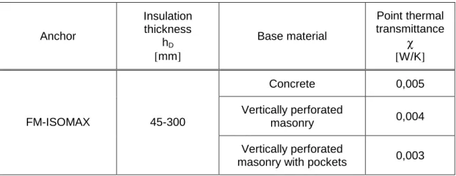
4.2.1.5 Point thermal transmittance according EOTA Technical Report TR 025
The point thermal transmittance (χ) of the anchor according EOTA Technical Report TR
025 “Determination of point thermal transmittance of plastic anchors for the anchorage of external thermal insulation composite systems (ETICS)” is given in the following Table for use category A, B and C respectively.
Table 4.1: Point thermal transmittance
Anchor Insulation thickness hD [mm] Base material Point thermal transmittance χ [W/K] Concrete 0,005 Vertically perforated masonry 0,004 FM-ISOMAX 45-300 Vertically perforated
4.2.1.6 Plate stiffness according to EOTA Technical Report TR 026 No performance determined.
4.2.2 Installation of anchors
The fitness for use of the anchor can only be assumed if the following conditions are met:
− Anchor installation carried out by appropriately qualified personnel and under the
supervision of the person responsible for technical matters on the site.
− Use of the anchor only as supplied by the manufacturer without exchanging the
components of an anchor.
− Anchor installation in accordance with the manufacturer’s specifications and
drawings using the tools indicated in this European Technical Approval.
− Checks before placing the anchor to ensure that the characteristic values of the
base material in which the anchor is to be placed, is identical with the values, which the characteristic loads apply for.
− Observation of the drill method (Drill holes in masonry made of verticaly preforated
clay bricks may only be drilled using the rotary drill. Other drilling methods may also be used if job site tests according to 4.2.3 evaluate the influence of hammer or impact drilling).
− Placing drill holes without damaging the reinforcement.
− Temperature during the installation of the anchor ≥ 5ºC.
− Exposure to UV due to solar radiation of the anchor not protected by rendering ≤ 6
weeks.
4.2.3 Job site tests
The characteristic tension resistance of the anchor may be determined by means of job site pull-out tests carried out on the material actually used, if a characteristic resistance of the base material does not exist (for example masonry made of solid masonry units). The characteristic resistance of the anchor shall be determined by carrying out at least 15 centric tension pull-out tests on site. These tests are also possible under same conditions in a laboratory.
Execution and evaluation of these tests as well as the issue of the test report and the determination of the characteristic resistance should be under responsibility of approved testing laboratories or the supervision of the person responsible for the execution of the works on site.
Number and position of the anchors to be tested shall be adapted to the relevant special conditions of the site and, for example, to be increased in the case of hidden and larger areas, such that reliable information about the characteristic resistance of the anchor in the base material in question can be derived. The tests shall take into account the most unfavourable conditions of the practical execution.
4.2.3.1 Assembly
The anchor to be tested shall be installed (e.g. preparation of drill hole, drilling tool to be used, drill bit) and the spacing and the edge distance shall be in the same way as planned for the fixing of external thermal insulation composite system.
Depending on the drilling tool and according to ISO 5468, hard metal hammer-drill bits or hard metal percussion drill bits, respectively, shall be used. The cutting diameter shall be at the upper tolerance limit.
4.2.3.2 Execution of test
The test rig used for the pull-out tests shall provide a continuous slow increase of the load, controlled by a calibrated load cell. The load shall apply perpendicular to the surface of the base material and shall be transmitted to the anchor via an hinge. The reaction forces shall be transmitted into the base material at a distance at least 15 cm from the anchor. The load shell shall be increased continuously in a way, that the ultimate load is reached after about 1 minute. The load is measured when the ultimate load (N1) is
achieved. 4.2.3.3 Test report
The test report shall include all information necessary to assess the resistance of the tested anchor. It shall be included in the construction dossier.
The minimum data required are:
• Construction site, owner of building; date and location of the tests, air temperature;
tape of member (ETICS) to be fixed
• Masonry (type of brick, strength class, all dimensions of bricks, mortar group),
Visual assessment of masonry (flush joints, joint clearance, regularity),
• Plastic anchor and nail; value of the cutting diameter of hard metal hammer-drill
bits, measured before and after drilling,
• Test rig; results of tests including the indication of value N1
• Tests carried out or supervised by; signature.
4.2.3.4 Evaluation of test results
The characteristic resistance NRk1 is obtained from the measured values of N1 as follows:
NRk1 = 0.6 · N1≤ 1.5 kN
N1 = the mean value of the five smallest measured values at the ultimate load
Responsibility for the manufacturer
It is in the responsibility of the manufacturer to ensure that the information on the specific conditions according to 1 and 2 including Annexes referred to 4.2.1, 4.2.2 and 5 is given to those who are concerned. This information may be made by reproduction of the respective parts of the European Technical Approval. In addition, all installation data shall be shown clearly on the packaging and/or on an enclosed instruction sheet, preferably using illustration.
The minimum data required are:
− base material for the intended use,
− drill bit diameter,
− minimum effective anchorage depth,
− minimum hole depth,
− information on the installation procedure,
− identification of the manufacturing batch.
All data shall be presented in a clear and explicit form.
5 Indications to the manufacturer
5.1 Packing, transport and storage
The anchor shall only be supplied as a complete unit.
The anchor shall be stored under normal climatic conditions in its original light-proof packaging. Before installation, it shall not be extremely dried or frozen.
Leading expert:
Dušica Drobnič, M.Sc., Research Engineer
Head of the Service for Technical Approvals:
Franc Capuder, M.Sc. The original document is signed by both signatories
FM-ISOMAX
Intended use
Annex 1
of the European Technical Approval
Table 1: Dimensions
Anchor sleeve Accompanying
expansion nail Anchor type
dnom hef dN
[mm] [mm] [mm]
FM-ISOMAX 8 55 5
Various lengths of the anchor are permissible La min = 100 mm; La max = 360 mm
Determination of maximum thickness of insulation: hd = La – ttol – hef e.g. La = 160 mm
ttol = 0 mm hd = 160 mm – 0 mm -55 mm hd = 105 mm FM-ISOMAX Dimensions Annex 2
of the European Technical Approval
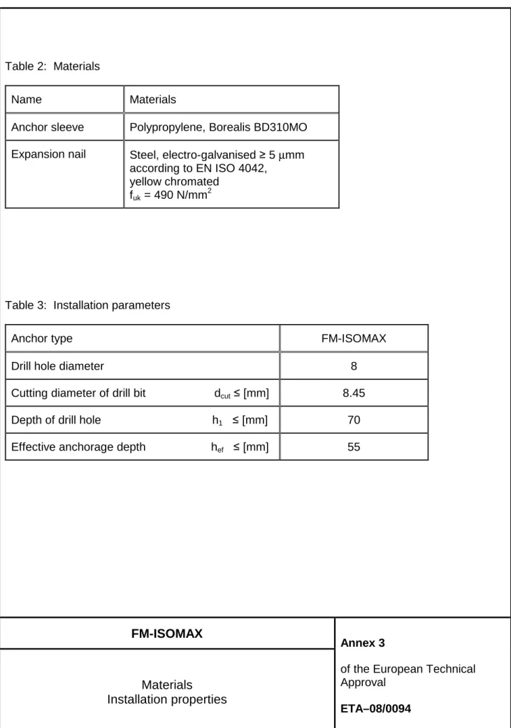
Table 2: Materials
Name Materials
Anchor sleeve Polypropylene, Borealis BD310MO
Expansion nail Steel, electro-galvanised ≥ 5 µmm
according to EN ISO 4042, yellow chromated
fuk = 490 N/mm
2
Table 3: Installation parameters
Anchor type FM-ISOMAX
Drill hole diameter 8
Cutting diameter of drill bit dcut≤ [mm] 8.45
Depth of drill hole h1 ≤ [mm] 70
Effective anchorage depth hef ≤ [mm] 55
FM-ISOMAX
Materials Installation properties
Annex 3
of the European Technical Approval
Table 4: Characteristic resistance to tension loads NRk in concrete and masonry for a single
anchor in kN
Base material Bulk
density [kg/m3] Minimum compression strength [MPa] General remarks NRk [kN] Concrete C 16/20 – C 50/60 SIST EN 206 - 1 0,4
Solid clay brick HD 250x120x65 mm
≥ 1600 28.2 0,3
Vertically perforated clay brick
LD 290x190x190 acc. SIST EN 771
≥ 1770 13.3
Exterior web thickness
≥ 9 mm
0,3
Vertically perforated clay brick with mortar pocket PTH 38 S LD 250x380x238 acc. SIST EN 771
≥ 1770 12.4
Exterior web thickness
≥ 10 mm
0,3
Partial safety factor 1) γM 2.0
1)
valid in absence other national regulations
FM-ISOMAX
Characteristic resistance
Annex 4
of the European Technical Approval
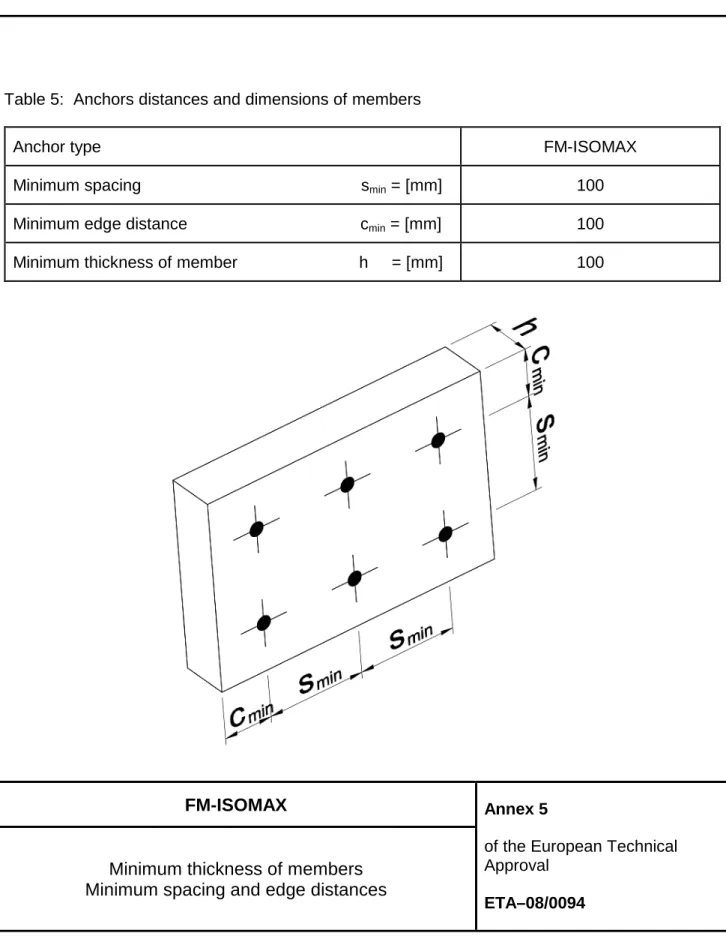
Table 5: Anchors distances and dimensions of members
Anchor type FM-ISOMAX
Minimum spacing smin = [mm] 100
Minimum edge distance cmin = [mm] 100
Minimum thickness of member h = [mm] 100
FM-ISOMAX
Minimum thickness of members Minimum spacing and edge distances
Annex 5
of the European Technical Approval
According to Construction Products Regulation CPR 305/2011/EU pg.1/2
Declaration of Performance
FM-ISOMAX via Trieste, 1 San Giovanni al Natisone
(UD) Italy - ph. +39 0432 747911 www.friulsider.com - [email protected]
Plastic anchor with steel nail for fixing of ETICS
Intended use or uses of the construction product according to ETAG014 and TR025*
Generic type Plastic anchor for multiple fixing for the anchorage of external thermal insulation composite systems with rendering (ETICS)
Base material (use category) > A: normal weight concrete acc. to EN 206-1 > B: Solid clay masonry acc. to EN 771-1
> C: hollow or perforated clay brick acc. to EN 771-1
Material Sleeve: Polypropylene acc.to ISO 1873-1 Nail: Zinc coated steel (f
uk ≥490N/mm²) the head as an additional plastic covers
Durability See ETA point 1.2
Loading only be used for transmission of wind suction loads and shall not be used for the transmission of dead loads of the ETICS
Fire Resistance NPD
Fire Reaction NPD
Point thermal transmittance* See table under
ETA-08/0094 issued by ZAG approval body nr.1404
On the basis of ETAG014
Certificate of Conformity 1404-CPD-1532 issued by ZAG notified body nr.1404
Under System (AVCP) 2+
Declared performances according to ETA-08/0094 (ETAG014)
Design method according to ETAG014
ESSENTIAL CHARACTERISTICS PERFORMANCE
Installation parameters FM-ISOMAX
d0 Nominal diameter of drill bit [mm] 8
hef Minimum effective anchorage depth [mm] 55
hmin Minimum thickness of base material [mm] 100
h1 Depth of drill hole to deepest point [mm] 70
smin Minimum spacing [mm] 100
cmin Minimum edge distance [mm] 100
Pull-out failure for use in Concrete
NRk,p Tension characteristic load in concreteC16/20÷C50/60 24°C2) / 40°C3) [kN] 0,4
Pull-out failure for use in Solid Clay Bricks HD 250x120x65 - fb ≥ 28,2 [MPa] - ≥ 1,6 [kg/dm3]
NRk,p Tension characteristic load 24°C2) / 40°C3) [kN] 0,3
Pull-out failure for use in Vertically perforated clay brick LD 290x190x190 - fb ≥ 13,3[MPa] - ≥ 1,77 [kg/dm3]
NRk,p Tension characteristic load 24°C2) / 40°C3) [kN] 0,3
Drill Method [-] Rotary drilling
Pull-out failure for use in Vertically perforated clay brick with mortar pocket PTH 38 S LD 250x380x238 - fb ≥ 12,4 [MPa] - ≥ 1,77 [kg/dm3]
NRk,p Tension characteristic load 24°C
2) / 40°C3)
[kN] 0,3
Drill Method [-] Rotary drilling
m 1) Partial safety factor [-] 2,0
1) In absence of other national regulations; 2) Maximum long term temperature; 3) Maximum short term temperature.
Declared performances according to TR025
ESSENTIAL CHARACTERISTICS PERFORMANCE
Point thermal transmittance
tfix 45÷300 [mm]
Concrete [W/K] 0,005
Vertically perforated masonry [W/K] 0,004
Vertically perforated masonry with mortar pocket [W/K] 0,003
We inform you that Friulsider is classified in the EC 1907/2006 Reach Directive as a Downstream-user of substances.
The product supplied does not contain substances classified as SVHC according to the Candidate List in a concentration equal or greater than 0.1% (weight / weight). Article 31 is not applicable to the present product.
Friulsider SpA DoP_isomax_rev.01
According to Construction Products Regulation CPR 305/2011/EU pg.2/2
The above performances apply for the following article numbers:
dnom5) L 5) [mm] tfix 6) [mm] Marking Cod. Ø8 100 45 PSK 100/Ø8 61925008100 120 65 PSK 120/Ø8 61925008100 140 85 PSK 140/Ø8 61925008100 160 105 PSK 160/Ø8 61925008100 180 125 PSK 180/Ø8 61925008100 200 145 PSK 200/Ø8 61925008100 220 165 PSK 220/Ø8 61925008100 260 205 PSK 260/Ø8 61925008100 300 245 PSK 300/Ø8 61925008100 360 305 PSK 360/Ø8 61925008100
4) Diameter of anchor sleeve; 5) Length of anchor; 6) Thickness fixture max.
The performances of the product identified by the above identification code are in conformity with the declared performance. This declaration of performance is issued under the sole responsibility of Friulsider SpA.
Signed for and behalf of the manufacturer by:
Name and functions Place and date of issue Signature
Eng.Vittorio Pilla