ROMAN FLOREA
NETWORKING SOLUTIONS FOR INTEGRATED
HETEROGENEOUS WIRELESS ECOSYSTEM
Master of Science thesis
Examiners: Prof. Yevgeni Koucheryavy and
Dr. Sergey Andreev
Examiners and topic approved by the Faculty Council of the Faculty of
Electronics and Communications Engineering on 4th May 2016
i
ABSTRACT
ROMAN FLOREA: Networking Solutions for Integrated Heterogeneous Wireless Ecosystem
Tampere University of Technology
Master of Science thesis, 57 pages, 5 Appendix pages June 2016
Master’s Degree Programme in Information Technology Major: Communication Systems and Networks
Examiners: Prof. Yevgeni Koucheryavy and Dr. Sergey Andreev
Keywords: traffic offloading, heterogeneous network, SDN, LTE, WiFi, 5G
This work targets at applying computer networking techniques to address challenges in modern wireless networks and in various environments built around these net-works. The main focus of the work is on designing and implementing prototypes and demonstrators to support research in domains of heterogeneous networks (Het-Nets). These research domains include centralized radio resource management in emerging cellular network architectures, network assistance role in device-to-device (D2D) communications, and studying prospective services in these networks. Within the research group the author was tasked with designing network architectures and demonstrating certain connectivity and functionality interesting for the research. The author was responsible for modifying commercial off-the-shelf equipment to be-come suitable for target research scenarios, selecting network technologies to achieve connectivity requirements, deploying network architecture entities within the re-search group’s cloud platform. For HetNet track, the primary goal was to design a platform that would mimic a device connected through a heterogeneous network, allowing researchers to experiment with traffic flow optimization in an environment close to the envisioned next-generation network architecture. Prototype solution and testbed were designed building on software defined network principles of au-tomation, abstraction and software based flow switching, and were implemented using overlay networks and virtual network functions. Within D2D communications research, the task was to design architecture demonstrating feasibility of traffic of-floading from infrastructure network to direct links. Prototype was implemented with automated routing control in overlay network. To demonstrate novel services enabled by advanced security frameworks, D2D platform was augmented and a new network application has been implemented, also suitable for wearable electronics.
ii
PREFACE
This work concludes 3 years of the author’s activity within the Department of Elec-tronics and Communications Engineering, Tampere University of Technology, Fin-land. The results presented in this thesis developed from multiple collaborations with other researchers and constitute a part of larger scale scientific effort within the research group.
I would like to thank Dr. Sergey Andreev and Prof. Yevgeni Koucheryavy for initiat-ing me to the academic world and acknowledge their guidance throughout my work at the department. Also this work wouldn’t be possible without all the brilliant peo-ple whom I was fortunate to meet at the research group. Furthermore, my deepest appreciations go to my comrades in arms Adam Surák and Aleksandr Ometov for their friendship and collaboration in both scientific and normal lives.
Finally, this achievement would be meaningless without my beloved Anna, my par-ents and other family members.
This work was supported in part by Intel Corporation, the Academy of Finland (project “Empowering Secure, Private, and Trusted Network-Assisted Device-to-Device Communication”), and the Internet of Things Program of DIGILE, funded by Tekes.
Tampere, 23.5.2016
iii
TABLE OF CONTENTS
1. Introduction . . . 1 1.1 Motivation . . . 1 1.2 Potential solutions . . . 2 1.3 Overview of tools . . . 31.4 Structure of this work . . . 5
2. Centralized radio resource management in HetNets . . . 7
2.1 Introduction and motivation . . . 7
2.2 H-CRAN: technology and standards background . . . 10
2.3 Practical testbed implementations . . . 13
2.3.1 Implemented R&S demonstrator . . . 13
2.3.2 H-CRAN architecture prototype . . . 14
2.3.3 Infrastructure for the prototype . . . 16
2.4 Technical details . . . 17
2.4.1 Toolchains and custom software on user equipment . . . 17
2.4.2 OpenFlow software switch . . . 18
2.4.3 Network side . . . 19
2.4.4 Architecture summary and workflow . . . 21
2.5 Conclusions on coordinated resource management . . . 22
3. Network assisted device-to-device communications . . . 24
3.1 Introduction and motivation . . . 24
3.2 Network assistance in D2D communications . . . 25
3.3 Implementing traffic offloading prototype . . . 29
3.3.1 Android networking subsystem . . . 29
3.3.2 Traffic offloading based on routing . . . 31
iv
3.4 Prototype implementation technical details . . . 35
3.4.1 User equipment . . . 35
3.4.2 D2D server . . . 37
3.4.3 Content register . . . 37
3.4.4 Utility nodes . . . 38
3.5 Conclusions on network-assisted D2D communications . . . 38
4. Security and trust in proposed ecosystem . . . 41
4.1 Securing network-assisted D2D communications . . . 41
4.2 Characterization of cryptographic primitives in IoT . . . 44
4.3 Applications of secure and trusted D2D connectivity . . . 47
5. Conclusions . . . 49
BIBLIOGRAPHY . . . 52
v
LIST OF FIGURES
2.1 Example of H-CRAN deployment and system modes . . . 11
2.2 Setup with Rohde and Schwartz CMW500 . . . 14
2.3 Proposed testbed topology for multi-RAT HetNets . . . 16
2.4 Overall architecture of prototype implementation . . . 17
2.5 Detailed network architecture of VPN server . . . 20
2.6 Setup with WAN emulation node . . . 21
3.1 Assisted D2D connection establishment via D2D server . . . 28
3.2 Proposed D2D services layout . . . 30
3.3 Prototype setup for D2D architecture . . . 35
3.4 D2D video presentation . . . 40
4.1 Connectivity example for security framework . . . 42
4.2 Demonstration of security framework application . . . 43
4.3 Devices used in assessments . . . 46
vi
LIST OF ABBREVIATIONS AND SYMBOLS
3GPP Third Generation Partnership Project4G Fourth Generation
5G Fifth Generation
ANDSF Access Network Discovery and Selection Function
AP Access Point
BBU Base Band Unit
BGP Border Gateway Protocol
BS Base Station
CAPEX Capital Expenditure COTS Commercial Off-The-Shelf
CRRM Cooperative Radio Resource Management D2D Device-to-device
GRE Generic Routing Encapsulation HetNet Heterogeneous Network
IoT Internet of Things
LPN Low Power Node
LXC Linux Container
MIMO Multiple-Input and Multiple-Output NAT Network Address Translation
NFV Network Functions Virtualization OPEX Operational Expenditure
OVS Open vSwitch
PBR Policy Based Routing POP Point Of Presence PoC Proof of Concept QoS Quality of Service
RAT Radio Access Technology
RPM RPM Package Manager
RRH Remote Radio Head
RSA Rivest, Shamir, Adleman
RSSI Received Signal Strength Indicator SDK Software Development Kit
vii SLA Service Level Agreement
TUT Tampere University of Technology
UE User Equipment
URL Uniform Resource Locator VETH Virtual Ethernet
VM Virtual Machine
WFD WiFi Direct
eSMLC Evolved Serving Mobile Location Centre ePC Evolved Packet Core
eNodeB Evolved Node B mmWave Millimeter Wave
1
1.
INTRODUCTION
1.1
Motivation
The evolution of wireless communications over the last decades has brought us to a point where users demand “anytime, anywhere” high speed mobile Internet access, and have high expectations on service quality (in terms of bandwith, latency, service continuity, privacy, security, etc.). Completion of the fourth generation (4G) of broadband communication standards in 2011 has introduced drastic improvements to the wireless systems deployments in terms of capacity, energy efficiency, and quality of service. Year 2015 was the first time when 4G traffic exceeded third-generation (3G) traffic [1]. Recently, the share of 4G mobile connections was at 14% and 4G mobile data traffic reached 47% [1], while current research efforts are shifting focus towards elaborating solutions that would comprise what may be referred to as fifth generation (5G) wireless networks. First deployments of 5G systems are expected around year 2020, which would conclude a historical 10-year cycle for a generation of communications standards.
Even though it is not yet exactly clear what technologies would comprise a 5G network, the trends in communications engineering and user demands already shape our vision on network requirements. As global mobile traffic increased with 1.6 exabytes of data per month in year 2015 (which makes it a 74 percent growth [1]), service providers seek ways to fulfill the ever increasing user expectations on being connected to the Internet at any location, with the ability to enjoy all the multimedia services offered through the network at any time. These demands for uniform connectivity regardless of users’ location, who their connection peers are, and what their preferred services are, pose significant challenges to the development of 5G technology to provide matching data rates.
However, modern wireless networks currently lack what it takes to provide expe-rience of ubiquitous connectivity. Currently, the networks are unable to deliver
1.2. Potential solutions 2
uniform data rates and are subject to excessive time delays, or even service dis-ruptions due to coverage issues and influence of interference conditions. Current technologies brought us a leap forward in dealing with these challenges; however, they are predicted to be unable to cope with anticipated (nearly eightfold between 2015 and 2020 [1]) growth in traffic demands, driven by quick evolution of wire-less devices in kinds and amounts. The picture is overshadowed by emerging huge amounts of various machine-type devices, taking the stage in the upcoming Internet of Things (IoT) era. These technology challenges emphasize the drive for research of novel approaches under the 5G network architecture initiatives.
1.2
Potential solutions
Fortunately, the evolution of Information Technology (IT) and communications is not all about challenges. Over the last decade the evolution of technology in various directions like cloud computing, virtualization, high speed fiber optics communica-tions, efficient signal processing, advances in data center IT architectures, etc., has provided researchers and engineers with powerful tools for elaborating future-proof solutions to modern challenging demands.
Heterogeneous multi-radio architectures for mobile networks (HetNets) are mod-ern solution for service providers, brought to address emerging connectivity de-mands by hierarchically adding smaller and smaller cells. The resulting setup allows user device to interact with the infrastructure via multiple radio access technologies (RATs). While more and more user devices are being equipped with multiple ra-dio transceivers, this architecture allows mobile network operators to significantly improve network capacity by efficiently utilizing spectra of these radio technologies, thus offering higher quality of experience to their customers.
Thorough study of integration of new RATs, and understanding of required intelli-gence sharing between user equipment (UE) and infrastructure, for efficient use of these technologies, are envisioned to be fundamental enablers for future 5G stan-dards. A confirmed example of benefits brought by HetNet architectures could be performance improvements in an unlicensed-band network, like WiFi, by leveraging centralized control from designated entity in mobile network core, like 3GPP LTE [2].
1.3. Overview of tools 3
software elaboration, operation, and evaluation principles very attractive to other technology fields. Software Defined Networking (SDN) paradigm comprises a set of automation and abstraction concepts aimed to bring networking closer to its ultimate goal of interconnecting users and applications in the most efficient way, by providing entities that use the network with tools to shape network services to their needs. Within the scope of this work, SDN vision aligns well with HetNet architectures in desire to optimize resource allocation through centralized decisions, based on end-to-end view of traffic flows, and in attempt to involve both user and network sides of communication into optimization process, while allowing UE to efficiently use all the available communication technologies. While, the term SDN is relatively new, and there is a lot of debate around SDN concepts going among researchers, engineers, and equipment vendors, the principles of network control automation, abstraction from underlying network functionality, and software based flow switching laid foundation for prototyping within this research work.
Another networking solution proved useful in research and development of new ar-chitectures is the concept of overlay networks. Building another logical network layer on top of existing transport network is useful in highly dynamic environments like data centers, or in cases where major changes to underlay transport network are very expensive, like in large scale operator networks. Within this work, config-uring tunnels over different provider networks and different technologies allowed to achieve desired connectivity without modifying underlying network protocols, which otherwise would require open access to a live cellular installation. The drawback is increased overhead in the network, but it does not interfere with research objectives and is acceptable for the scope of this work.
1.3
Overview of tools
Open VPN
Open VPN is a network tunneling software. Open VPN is widespread due to its openness, and availability for a variety of platforms. Particularly interesting for this project is its capability to dynamically deploy and execute custom applications or scripts on connecting client, based on triggered events, and capability to run as remote gateway interconnecting multiple private networks.
1.3. Overview of tools 4
Open vSwitch
Open vSwitch is a multilayer software switch. Important feature for the project is its ability to expose forwarding functions to remote entities for programmatic extension and control via protocols like OpenFlow.
VMware vSphere
Easy to use and well documented virtualization solution. Used to abstract and share physical server resources to multiple virtual machines. Important feature is its robustness.
Docker
Software packaging solution, allowing to isolate an application at OS kernel level together with all required dependencies, files and network interfaces in a standard-ized unit – container. Used for persistent and automated deployment and runtime across various environments.
GRE
General Routing Encapsulation is simple tunneling protocol used to build overlay networks on top of IP networks. Important feature is its capability to encapsulate various protocols including Ethernet.
NFV
Network Functions Virtualization is a concept complementary to SDN. NFV sug-gests new way to implement and operate network functions, by abstracting them from hardware appliances and using virtualization techniques to package these func-tions as virtual machines running on generic hardware.
1.4. Structure of this work 5
1.4
Structure of this work
This work is concerned with prototyping solutions to address several challenges in streamlined delivery of connectivity with high service experience over the multi-radio heterogeneous deployments to a variety of modern handheld and wearable mobile devices. Chapters 2 and 3 cover the author’s work within the research on enabling technologies, namely Heterogeneous Networks [2, 3] and Device-to-Device communications [4, 5]. Chapter 4 describes research on prospective applications based on these enabling technologies [6, 7]. This thesis is structured as follows.
• Chapter 1 introduces evolution trends in modern wireless networks. Driven by all increasing connectivity demands, research and engineering communities are working on defining and implementing next generation networks. Main motivators for the research are mentioned in Section 1.1, and the following Section 1.2 outlines research areas of the group within which this work was done.
• Chapter 2 focuses on prototypes and demonstrators developed to support re-search done on optimization problems in cooperative radio resource manage-ment in Heterogeneous Cloud Radio Access Network (H-CRAN). Section 2.1 describes coordination issues in prospective 5G deployments, and introduces a combination of HetNet principles with C-RAN. Section 2.2 outlines coordi-nation schemes evolution, concluding with envisioned H-CRAN architecture. General features of the testbed implementation are described in Section 2.3 with technical details specified in Section 2.4. Chapter is concluded with the list of achieved results presented in Section 2.5.
• Research activities outlined in Chapter 3 aim to use traffic control princi-ples similar to Chapter 2, by utilizing direct link between proximate users to offload communications from infrastructure. Section 3.1 begins with intro-duction to main factors driving the search for new ways to increase network capacity. Section 3.2 introduces research on improvements in D2D commu-nications, brought by network assistance. Solution prototype is described in Section 3.3, with technical details laid out in Section 3.4. The results of pro-totype implementation process are presented in Section 3.5
• Chapter 4 elaborates on security and trust research in heterogeneous wire-less ecosystems. Section 4.1 outlines research conducted on a novel algorithm
1.4. Structure of this work 6
to maintain security functions of proximate devices in case of unreliable cel-lular connectivity, covering cases when a new device joins the secure group of users or an existing device leaves it. Section 4.2 addresses prototyping to support study of applicability of modern cryptographic primitives, including the pairing-based cryptography, to another emerging area where security is vital – new kind of smart electronics known aswearables. Section 4.3 suggests potential services enabled by an integrated heterogeneous wireless ecosystem.
7
2.
CENTRALIZED RADIO RESOURCE
MANAGEMENT IN HETNETS
5G communications ecosystem targets to reach higher rates never challenged be-fore, and to keep up with these rates, modern heterogenous network architectures have already developed improved ways to integrate various RATs. Seeking new vectors for evolution, emerging paradigm of heterogeneous cloud radio access net-work (H-CRAN) merges RAT integration with advanced cloud infrastructures. This approach enables improved management on the network-wide scale, allowing to im-plement cross-cell radio resource allocation in a coordinated way. Recent research addressed the gaps in theoretical performance analysis, and provided assessment and mathematical methodology for real-time optimization of cooperative radio re-source management in H-CRAN [2]. Resulting algorithms allow to balance between throughput and fairness metrics in a flexible way, as might align with network oper-ator’s development plans. Also, this approach demonstrated some advantages over state-of-the-art multi-radio resource allocation schemes.
This chapter introduces work on elaborating practical implementation of a proof-of-concept prototype, to demonstrate feasibility of algorithms for cooperative resource management in H-CRAN.
2.1
Introduction and motivation
In the upcoming 5G era, most of the modern conveniences could use wireless net-works to push our understanding of quality of life even further, and provide even broader spectrum of services. This vision poses unprecedented challenges to those who research, develop, deploy and operate theses networks as the demand for mobile data traffic is expected to increase nearly eightfold in the period from years 2015 to 2020, reaching as much as 30.6 exabytes globally per month [1]. To provide service matching these demands, wireless networks would be required to support very dense
2.1. Introduction and motivation 8
user device and network infrastructure nodes placements, employ very high carrier frequencies including emerging millimeter wave (mmWave) technologies, and utilize larger numbers of antennas in massive multiple-input multiple-output (MIMO) in-stallations [8]. Together with harnessing additional spectral resources, network man-agement needs to be improved, to be able to operate prospective 5G deployments in an intelligent and flexible way, also paying attention to increasing importance of power and cost effectiveness. An emerging paradigm of HetNet is expected to be the advanced networking architecture to address these challenges. Utilizing 3GPP LTE macro cells for complete coverage, this architecture is enhancing connectivity and capacity, by augmenting infrastructure with small cells varying in RAT and in size. This approach allows to use both licensed and unlicensed spectra, supporting user access in open, closed or hybrid fashion [9], and to connect users through tech-nologies like pico and femto cells, remote radio heads (RRHs), relay nodes, WiFi and WiGig access points, integrated WiFi-LTE small cells, etc. Significant gains in capacity and overall user experience can be achieved by applying efficient coordina-tion to this variety of RANs [10]. However, to maximize the flexibility of HetNet management for robust interference mitigation, mobile connectivity continuity, and enhanced capacity [11], all of the macro nodes and small cells have to be intercon-nected via low-latency high-rate backhaul links, which significantly increases capital expenditure (CAPEX) and operational expenditure (OPEX).
Different coordination schemes can be applied to 5G HetNet architecture depending on backhaul available to network operator. In case backhaul deployment is restricted
tonon-ideal infrastructure, the coordination can be performed in anchor-booster
ar-chitecture, where general network management is provided by anchor macro base station (BS), and multi-radio small cells offer opportunistic traffic offloading capabil-ity to boost user data rates. Otherwise, if backhaul is providing higher capaccapabil-ity and lower latency, by using near-ideal carrier (e.g., optical fiber), low-power small cells can offload processing of baseband signals, by forwarding them to a remote central-ized server platform. Network operators with wide fiber infrastructure deployments tend to prefer the latter approach, named Cloud RAN (C-RAN), by employing inex-pensive wireless installations for front-haul connections, primarily in areas with high traffic demands requiring ultra-dense HetNet deployments. This way the concept of C-RAN allows to substantially lower operator’s CAPEX and OPEX, considering that the largest part of infrastructure investments by a network operator are spent on RAN part [12]. Additionally, C-RAN architecture is much more efficient in terms of wireless infrastructure energy consumption.
2.1. Introduction and motivation 9
The RRH unit in C-RAN is a simplified low-power node, acting as a soft relay by compressing baseband signals from mobile UE and sending them to the centralized base band unit (BBU) over high-rate front-haul links. In such setup, front-haul con-nections can become capacity bottlenecks, thus requiring advanced signal processing solutions [13] and dynamic resource management [14] to maintain needed levels of performance. Some key points shaping C-RAN capacity include
• Proper optimization [15] addressing practical backhaul constrants [16]
• Uplink RRH association strategies [17] with corresponding restrictions on im-plementation complexity and radio resource consumption [18]
• Employed decentralized beamforming algorithms [19] and large-scale distributed MIMO-aware power and antenna selection schemes [20]
Combination of HetNet principles with C-RAN “signal processing cloud” has re-cently emerged as the Heterogeneous Cloud RAN (H-CRAN) concept, aimed to further improve cooperative gains in a cost-efficient way. H-CRAN takes best from both worlds, by blending networking techniques of heterogeneous networking with cooperative processing of cloud computing, thus enabling facilitated interference mitigation, scalable deployments, and efficient radio resource control. The function of managing radio resources of low-power nodes (LPNs) is delegated to a virtual BS, which runs in the cloud and is allocated from total processing capacity available at the physical BBU pool. Currently, main research focus was to outline technological features and base principles of H-CRAN to lay foundation for commercial H-CRAN based 5G systems [21]; however, to gain ultimate understanding of its capabilities there are still major challenges in the fields of theoretical performance analysis and optimal resource allocation to be addressed.
Recent research has focused on the problem of cooperative radio resource manage-ment in 5G-grade H-CRAN systems and provided a comprehensive methodology for real-time performance optimization of H-CRANs [2]. Proposed solution allows to dynamically control the amount of resources allocated to end users, for two alter-native metrics of interest, namely, the fairness of resulting resource shares across all the available RANs, and the overall system throughput. This work describes implementation of several testbeds, to support the research on exploiting trade-offs between fairness and throughput metrics, and development of proof-of-concept
2.2. H-CRAN: technology and standards background 10
demonstrations of network-centric, network-assisted, and UE-centric resource allo-cation mechanisms in characteristic H-CRAN environment, with different levels of available LTE/WiFi integration.
2.2
H-CRAN: technology and standards background
Although H-CRAN technology is still not ready for commercial use in production networks, coordinated use of multiple RATs within single multi-radio network man-aged by the operator is becoming actively researched in 3GPP. This section reviews some of the respective efforts.
3GPP Release 11 introduced loose coordination model, where access network dis-covery and selection function (ANDSF) is managing interworking between WLAN and 3GPP technologies (see TS 23.402), by means of ANDSF policy server inside core network. The operator specifies discovery and WLAN resource usage within the network, by defining relatively static policies, and the UE makes actual network selection based on local operating environment and changes in radio link conditions. ANDSF-enabled architecture is shown in Figure 2.1(a).
Major drawback of ANDSF is thatUE-centric decisions are sub-optimal as UE does not have complete vision of other users sharing radio network, their link conditions and radio resource requirements. Also, multi-radio cells within HetNet deployments do not share information about each other’s state, conditions, and radio resource usage. This diminishes network-wide radio resource utilization even further. Ad-ditionally, placement of mobility anchor in the network core (at P-GW typically) makes it very expensive resource-wise to allow UE to steer traffic across WLAN and 3GPP links when link conditions change rapidly.
These WLAN/3GPP radio interworking issues were alleviated to some extent in Release 12 (see TR 37.834). Traffic steering between WLAN and 3GPP RANs can be facilitated by setting link quality and WLAN load thresholds at cellular BS (eNB or eNodeB) through internal coordination within RAN. However, the standards did not specify coordination required in the network to set appropriate thresholds. Also, steering traffic in a flexible and efficient way is still not feasible as mobility anchor of WLAN/3GPP links is still defined in the core network by the standard. The mechanisms based on this integration option will be referred to as network-assisted
2.2. H-CRAN: technology and standards background 11 S1u eNodeB Trusted AP Untrusted AP S-GW PDN-GW ePDG AAA Server ANDSF Server S2a STa SWn S2a S2a S2b SWm S6b RAN ePC
(a) ANDSF-enabled architecture
RRH Trusted AP BBU S1u RAN ePC To other nodes S-GW RRM R-GW Fronthaul
(b) Integrated anchor-booster system design Pico RRH Pico RRH UE UE UE Macro BS
Macro BBU Macro BS
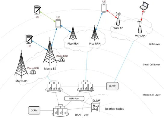
Macro BBU To other nodes BBU Pool R-GW CCRM WiFi AP WiFi AP UE UE S-GW RAN ePC
Macro Cell Layer Small Cell Layer
WiFi Layer
(c) Centralized Management in H-CRAN
2.2. H-CRAN: technology and standards background 12
To make integration of WLAN within 3GPP RAN tighter, recent proposals (see e.g., RP-140685, RP-140738) are targeting to incorporate WLAN as a secondary carrier within the 3GPP RAN, anchored at the eNB. Release 13 is expected to consider the proposed architecture for standardization, extending benefits of system design introduced for 3GPP small cells by Release 12 dual connectivity anchor-booster system design (see TR 36.842), and extending existing 3GPP carrier aggregation framework to also include non-3GPP RATs e.g., WLAN, like in the illustration used in this chapter.
If 3GPP will also consider standardizing the interface between eNB and WLAN access points (APs) for non-collocated WLAN/3GPP deployments, this integrated
network-controlled architecture will enable coordinated radio resource management
for non-3GPP WLAN networks thus extending the benefits of LTE-based anchor-booster schemes. Also, anchoring WLAN connections at eNB will allow users to delegate WLAN control and management functions to LTE network and use WLAN capacity solely for data offloading. Figure 2.1(b), shows simplified architecture of this approach. Radio resource management function is marked as RRM module in the plot, and designated gateway performing interface matching to connect WiFi and BBU is marked as RAN gateway or R-GW in the figure, as respective interface is not yet standardized.
Another 3GPP study (see TR 37.870) is currently exploring architecture for multi-RAT networks with enabled radio resource coordination across anchor cells, in ad-dition to coordinated use of radio resources within anchor cell coverage area, thus improving overall system performance even further. eNB to eNB coordination in the distributed model may be achieved over X2 interface; however, in practice, dif-ferent approaches may be used e.g., utilizing a centralized radio resource controller to manage radio resources system-wide.
Cloud RAN architecture becomes feasible in deployments, where high-rate fiber con-nections are available in the backhaul. Linking simple RRH with restricted function-ality to centralized BBU pool within the cloud, such architecture wraps entire RAN functionality within a single centralized node, thus significantly facilitating intro-duction of non-3GPP RRH nodes to allow for centralized multi-radio coordination. However, this requires additional standardization efforts from 3GPP.
Using principles similar to the multi-radio Cloud RAN, conceptual H-CRAN archi-tecture introduced in [21] and reviewed in Section 2.1 enables centralized processing
2.3. Practical testbed implementations 13
within the EPC, by connecting nodes to centralized server using S1 interface. Re-sulting centralized network control allows to perform coordinated/cooperative radio resource management, basing decisions on additional factors like variations in load (e.g., busy hour effect) and UE mobility (e.g., by offloading high mobility UEs to macro cell by default).
This chapter focuses on a H-CRAN deployment, where centralized management of system radio resources is performed by a dedicated entity, named Cooperative Radio Resource Manager (CRRM), and assuming same X2 backhaul interfaces for connection to the CRRM server. Deployment and system model of this approach are shown in Figure 2.1(c).
2.3
Practical testbed implementations
The following step of this research is to implement considered algorithms in an operational testbed, to study their practical performance. This section discusses realistic requirements for the implementation of proposed methodology. For this purpose, it is required to integrate resource allocation algorithms into the protocol stack of modern LTE and WiFi networks.
2.3.1
Implemented R&S demonstrator
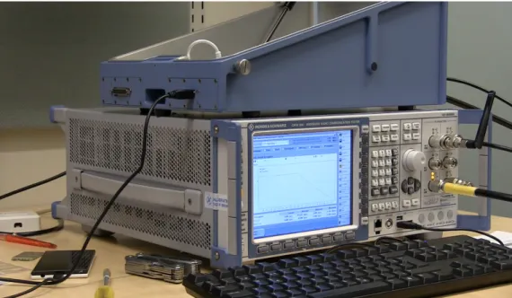
Recently, our research group at TUT, including author of this work, has com-pleted underlying HetNet testbed configuration, based on LTE eNodeB emulator, CMW500, by Rohde and Schwarz1. In this experiment, CMW500 was readily set
up for a scenario of offloading traffic from LTE to WiFi, to assess capabilities of CMW500 equipment for 5G research. Integration example demonstrated a simple handover scheme for WiFi-LTE data offloading case, where WiFi signal strength was main deciding factor. CMW500 was configured with LTE FDD cell signaling on frequency band 7, downlink 2645 MHz, uplink 2525 MHz, total bandwidth = 20 MHz. WiFi AP and CMW500 were bridged at the same server, which was also con-figured to lease IP addresses to UE via DHCP. An RF Shield Box model CMW-Z10 was used to control WiFi link quality. The shield box was connected to CMW500 unit via RF1 COM port and served as antenna for cellular link. This way, UE
1Video presentation of the experiment with R&S CMW500:
2.3. Practical testbed implementations 14
Figure 2.2 Setup with Rohde and Schwartz CMW500
placed into open shield box connected to gateway server via both LTE and WiFi and was able to use the link with a better quality. Closing shield box lid intro-duced over 80 dB of digital attenuation for WiFi, thus triggering UE to switch its data transmission to LTE. When the lid was open again, WiFi link quality became better than that of LTE, and traffic was offloaded back to WiFi. CMW500 capa-bilities to emulate LTE provider’s network allowed to quickly setup a testbed for improved offloading logic design, for the purposes of 5G research. Further research targeted intelligent data offloading, by employing advanced LTE link parameters. Figure 2.2 demonstrates a short video presenting the setup. The video is available at http://winter-group.net/rohde-schwarz-tutorial/.
2.3.2
H-CRAN architecture prototype
Current prototype implements a multi-radio scenario, where a cellular network is coupled with a WiFi access point, thus providing UE with a possibility to seamlessly switch between two RATs, or to efficiently use both of them at the same time. Naturally, implementation of the proposed model requires access to cellular BS side. It also requires UE capable of exposing necessary control information over the available radio channels. However, development kits for mobile platforms currently available on the market provide very limited support to manipulate corresponding interfaces and data flows.
2.3. Practical testbed implementations 15
In this implementation, the UE was connected to a conventional cellular network and a separate local WiFi AP, both providing Internet connectivity via different ISPs. To simulate a common network behind both radio links, mobile phone estab-lishes two VPN connections bound to cellular and WiFi interfaces, respectively, and terminating at an aggregator node (which may be e.g., located in the Internet). The aggregator node, bridging two links, simulates a packet gateway in LTE network. To aggregate both links on UE side, Open vSwitch (OVS)2 was employed.
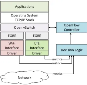
Cor-respondingly, vSwitch daemon, running on the phone, includes links representing WiFi and cellular connections together with a local virtual interface, serving as a bind point for outgoing traffic, generated by applications using sockets API. How-ever, specification of OVS assumes that all links in the virtual switch are able to handle Ethernet headers, which is not the case for cellular network exposed to sys-tem as a point-to-point RmNet interface. However, this issue could be solved by augmenting vSwitch to allow this type of interfaces, or by utilizing a module that would skip Ethernet header processing by an offset. In this testbed, author chose to add another layer of tunneling on top of existing VPN with a Generic Routing Encapsulation (GRE) tap tunnel (also referred as Ethernet GRE or EGRE) as the simplest in implementation, and for consistency, GRE tap layer has been added to WiFi VPN as well. Corresponding protocol stack of UE is outlined in Figure 2.3. Similar architecture is used at the aggregator on simulated operator side. This way, on the top level of abstraction architecture folds into two switches interconnected with two redundant links. Overall system topology is illustrated in Figure 2.4. The proposed setup allows us to implement a controller that would be able to main-tain vSwitch’s forwarding table using OpenFlow protocol3, and provide desired levels
of per-flow traffic steering (i.e., resource allocation) based on dynamic criteria. A separate module collects data from RATs about the state of every underlying physi-cal link, such as Received Signal Strength Indicator (RSSI) and radio signal strength. The controller uses these data to efficiently assign new flows to either of outgoing interfaces. Coming back to the analytical algorithm implementation, this means that it is possible to transfer implemented resource allocation logic (e.g., relative fairness scheme) into the OpenFlow controller and specify control channel interface (which is LTE in this case).
2Open vSwitch website: http://openvswitch.org/ 3OpenFlow website: https://www.opennetworking.org/
2.3. Practical testbed implementations 16 WiFi Interface EGRE LTE Interface EGRE Open vSwitch Applications Operating System TCP/IP Stack Driver Driver OpenFlow Controller Decision Logic Network metrics metrics metrics
Figure 2.3 Proposed testbed topology for multi-RAT HetNets
2.3.3
Infrastructure for the prototype
The network side entities were installed as virtual machines (VMs) running on vir-tualization platform, built with vSphere4 from VMWare. This approach allowed to deploy and interconnect architecture elements in a highly flexible and dynamic fashion. Virtualization platform was designed and assembled by a smaller group of research assistants, including the author of this work, to support various research activities performed by the larger group.
For the research scenario, WiFi access point was connected to the Internet through university network and configured as a router between wireless and wired sides. UE was connecting to both WiFi and LTE networks and had Internet connectivity through either network. Using specific static routes the UE was contacting particular VPN gateways over certain technology i.e., IP address of the gateway terminating LTE side VPN was routed via LTE network, with similar behavior for WiFi side. On the network side, traffic to the VPN aggregator node was chained by the platform through an entry node switch that was splitting traffic destined to LTE VPN and WiFi VPN, and then passed through WAN link emulator node. Details of such service chaining are illustrated in subsection 2.4.3.
2.4. Technical details 17
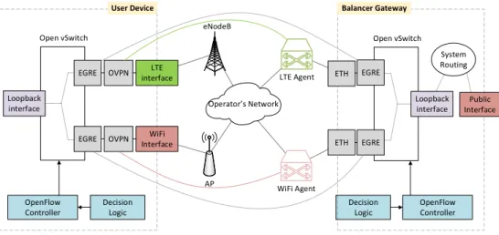
WiFi Interface OVPN interfaceLTE
OVPN EGRE EGRE Loopback interface OpenFlow Controller Open vSwitch Decision Logic User Device Operator s Network eNodeB AP LTE Agent WiFi Agent EGRE EGRE OpenFlow Controller Open vSwitch Decision Logic Balancer Gateway Loopback interface ETH ETH Public Interface System Routing
Figure 2.4 Overall architecture of prototype implementation
2.4
Technical details
Most important features of current prototype implementation are: software based switching, network control automation and overlay network over regular provider networks. Flow based switching was implemented with Open vSwitch software and network control was performed with OpenFlow controllers, both described in subsec-tion 2.4.2. Design of VPN and processes of measuring and influencing link condisubsec-tions are outlined in subsection 2.4.3. Significant work was done to prepare UE to handle these tools, subsection 2.4.1 covers modifications to the UE and procedures to enable it for research scenarios. Finally, architecture is summarized with the workflow of a research scenario in subsection 2.4.4.
2.4.1
Toolchains and custom software on user equipment
A suitable UE platform for testbed implementation has been the SailfishOS5running
on Jolla phones6, which combinesLinux andMER software7, and provides a flexible
platform software development kit (SDK). The platform offers all required tools to build custom kernel modules, as well as generic GNU\Linux software. Hence, in-stalling OVS, GRE, and Virtual Ethernet (VETH) modules, as well as OVS database and userspace tools, has been fairly straightforward. The software in SailfishOS is packaged with RPM Package Manager (RPM) (originally Red Hat Package Manager,
5Sailfish OS website: https://sailfishos.org/ 6Jolla phone website: http://jolla.com/ 7MER project website: http://merproject.org/
2.4. Technical details 18
now a recursive acronym), which provides powerful tools to integrate third-party software and to install additional components.
Some of the tools used in prototype require integration at OS kernel level, which means that UE kernel has to be built with corresponding functionality enabled. Customization of MER based Sailfish OS is done through Platform SDKs provided by the project. These platform SDK tools include compilers, Scratchbox2 cross-compilation toolkit, MIC image creator, Zypper package manager and other instru-ments to make development easier. In this setup, SDKs are run as an image in
a chroot environment; however, SDK can also be used as a dedicated virtual
ma-chine. SDK was installed on development machine from a rootfs tarball containing essential tools for MER platform development. The goal of using platform tools was to compile GRE, Open vSwtich, and VETH kernel modules for SailfishOS running on UE. As a basis for the new kernel configuration, author extracted configuration file from running system of a Jolla device. Configuration file was edited to include appropriate modules and was used for the build process, resulting in corresponding kernel object (.ko) files compiled. These module files were transferred to the UE and loaded into running kernel as part of prototype implementation. Another feature of the Platform SDK that was useful for us, is that provided cross-compiler toolchain
can be used to build custom userspace software, which is otherwise not available in official repositories. Using this toolchain, author was able to compile userspace part of OVS software.
2.4.2
OpenFlow software switch
OVS is a multilayer virtual switch, designed to target at multi-server virtualization deployments. It provides a lot of important features for highly dynamic environ-ments at large scales; however, for this prototype the most important feature of OVS is that it adheres to the emerging Software Defined Networking (SDN) paradigm and thus supports forwarding based on flow tables and can use OpenFlow as a method of exporting remote access to control traffic forwarding. These features enable flexible placement of traffic control entity (at UE itself, on network side, or combination of both), and per flow control over traffic forwarding, meaning that certain sessions can be selectively placed on WiFi or LTE interfaces in a dynamic way. OVS consists of kernel side module, responsible for actual packet forwarding in thedata-path, and userspace daemon, interacting with network state database and exposing control functions to external entities.
2.4. Technical details 19
OpenFlow based SDN vision implies that forwarding tables of a device should be maintained by a separate entity – the controller. This controller is responsible for making forwarding decisions and programming them into the flow tables along the data path, using Open Flow protocol. The controller in this installation was based on POX controller – a networking software platform written in Python8. Controller
assumes the management of UE’s forwarding plane consisting of 3 interfaces – WiFi interface, LTE interface, and internal system interface. Main task for controller is to run one of the optimizations algorithms supplied by researchers. Algorithm implementation receives metrics feed from the software, performing measurements of network conditions on both radio interfaces, and reallocates incoming and outgoing flows accordingly.
2.4.3
Network side
In the absence of access to an operational cellular network installation, researchers have to simulate joint control of WiFi and LTE networks for UE using VPN tunnels. This testbed used Open VPN for its simplicity and wide platform adoption. Clients would connect to dedicated VPN anchors through WiFi and LTE links, this way allowing the laboratory network to control setup of tunnel interfaces in a similar way as real operator network would control setup of physical links.
The authentication in VPN network is based on Rivest-Shamir-Adleman (RSA) certificates, as opposed to pre-shared key based authentication. Using EasyRSA tools, author has created certificate hierarchy where every user device would receive its own certificate to authenticate in the VPN network, and, based on information in that certificate, network would uniquely identify the user and configure it with predefined features.
Network-wise, VPN anchor was configured forsubnet layout. Unlike inpoint-to-point
layout, where a dedicated subnet is allocated for every client-server link, in subnet
layout all clients share common address space which slightly facilitates routing on the server side for prototype purposes.
During start up process, VPN agent places policy based routing (PBR) rules into routing subsystem, to selectively route traffic from VPN network to the gateway facing the Internet to provide external connectivity. Configuration of Open VPN
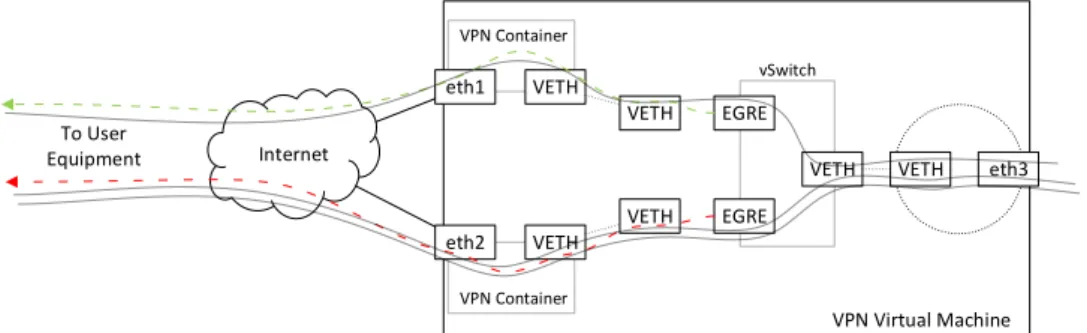
2.4. Technical details 20 Internet eth1 eth2 VPN Container VPN Container VETH VETH VETH VETH EGRE EGRE
VETH VETH eth3
vSwitch
VPN Virtual Machine To User
Equipment
Figure 2.5 Detailed network architecture of VPN server
server is provided with example of LTE agent in Listing 1
To separate operation domains of WiFi and LTE side VPN servers, without the need to run them on different virtual or physical nodes, both processes are exe-cuted on the same VM, isolated in dedicated Docker9 containers. Docker is a set of
tools that provide convenient way to manage Linux container (LXC) environments. Every container running openvpn process has in its namespace a dedicated host network interface, facing the client, and a VETH link bridged with host network. This way, openvpn container acts as a router between host side network, leading to internal operator network, and client network behind VPN network. Detailed net-work layout of the VPN server is presented in Figure 2.5. Container mounts into its internal filesystem a directory with corresponding configuration files and certificates (e.g., LTE directory for container running LTE side) and executes openvpn process according to these configuration files.
Most of commercial off the shelf (COTS) WiFi access points are shipped with pro-prietary, closed source operating systems, and are built with network chips run by closed drivers from hardware vendors. This way, access point becomes a “black box”, exposing enough control to set up the network, but prohibiting any new functional-ity on top of the hardware. For an access point to be useful in such research, both operating system and wireless interface firmware must be open, to allow modifica-tions and give access to internal variables. A good example of such device is a dual band WiFi router from Linksys model WRT1900AC. For this research the device was installed with OpenWRT10 system, custom compiled to include WiFi drivers
as modules, rather than built into the kernel, making it easier to dynamically add
9Docker platform: https://docs.docker.com
2.4. Technical details 21
changes into driver’s code. One of the most important changes to the operating system was to enable Linux debugfs filesystem that exposes multiple system values, like status of numerous transmit queues and current transmission rates.
This way, AP was prepared to send measurements of interest to the process imple-menting forwarding optimization logic, where the latter would combine WiFi state data with LTE data, or any other information found useful by researchers, like pri-oritization of users and RANs, and would yield new forwarding rules for UE side and operator side.
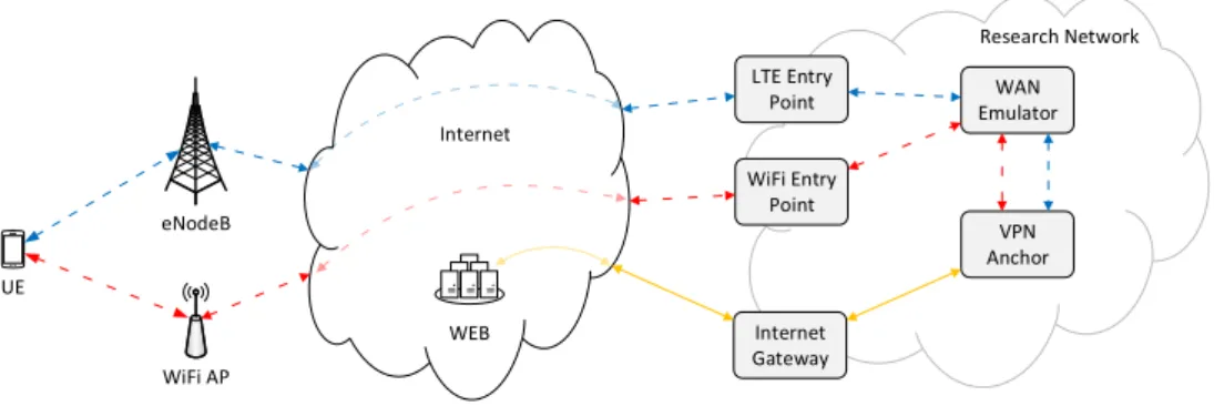
To simulate various network conditions, all traffic to the emulated aggregator node on network side was routed through a dedicated VM running WANem – a Wide Area Network Emulator11. This allowed us to impose various WAN characteristics
common to LTE networks, like network delay, packet loss, packet re-ordering, jitter, etc. to the links that are in fact running in research laboratory LAN. Such service chaining of traffic dedicated to one VM through another VM is not natively sup-ported by basic feature set of available vSphere installation, so several safety policies had to be disabled, and in such cases certain broadcast and unknown traffic should be suppressed by virtual switch, and greater caution should be paid when routing traffic, to avoid forwarding loops. Network scheme of traffic flows in the setup with WAN emulator node is demonstrated in Figure 2.6.
eNodeB UE WiFi AP Internet Gateway LTE Entry
Point EmulatorWAN Research Network WiFi Entry Point VPN Anchor Internet WEB
Figure 2.6 Setup with WAN emulation node
2.4.4
Architecture summary and workflow
Network side of the deployment consists of a number of VMs serving as VPN an-chor, WAN Emulation, and Internet Gateway. When VPN anchor VM boots up, it
2.5. Conclusions on coordinated resource management 22
performs the following steps
• starts VPN processes isolated in containers
• moves dedicated network interfaces to corresponding container namespaces
• creates a VETH pair for each container
• moves one end of every VETH pair to corresponding container namespace
• runs GRE tap tunnel to client over second end of VETH pair when client connects
• adds GRE tap interface to OVS
• creates another VETH pair for host networking
• adds one end of host VETH pair to vSwitch
• sets second end for routing to internal operator network
Code listing of the script starting the service is provided in Listing 3
When UE side and network side virtual forwarding planes are ready, both devices start measuring link qualities. Depending on coordination scheme scenario, con-troller software is started on either side and both virtual switches connect to it. Measurements from UE, AP, and operator side are also sent to the controller. This brings the setup to final operational state, where controller would use all available metrics, to run resource optimization algorithm provided by researchers, and would re-allocate traffic sessions across available links accordingly.
2.5
Conclusions on coordinated resource management
This chapter considered implementation of testbeds and demonstrators for H-CRAN – a recently emerged concept, brought to improve available cooperative gains in Het-Nets in a cost-efficient way. Elaborated solutions focused on improving research of coordinated radio resource management problem in 5G-grade H-CRANs, by imple-menting a platform to analyze their real-time performance optimization. The most important findings from development process are summarized below.
2.5. Conclusions on coordinated resource management 23
• Implementing a prototype for the CRRM unit helped to outline envisioned H-CRAN system architecture, based on review of respective 3GPP standard-ization processes and technology implementation options.
• Proposed architecture demonstrates viability of virtual forwarding planes con-cept for prototyping in traffic optimization research. Building an overlay net-work allows to abstract from actual netnet-work technologies that are closed to modifications, while preserving physical channel properties.
• Decoupling of measurement functions, traffic forwarding, and control enabled dynamic deployment of user centric, network assisted, and network controlled research scenarios, or other hybrid control schemes. Also, coordination logic can use any other information sources e.g., an even broader view on network at Internet scale from operator’s border gateway protocol (BGP).
• Using modern virtualization tools has proven to be crucial for fast and agile prototyping of new network architectures. This approach to packaging of soft-ware components allows to easily reproduce testbed setup in any hardsoft-ware or virtual environment, in an automated way. Virtualizing architecture entities also facilitates scaling up to allow wider setup, as well as scaling down to run self-contained installation on a researcher’s laptop.
• Resulting modular testbed allows to deploy new steering algorithms in a quick and automatic ways. The setup offers researchers an environment for testing traffic flow optimizations, similar to what the new architecture would be like in a live network.
• Prototype implementation improved research on H-CRAN resource optimiza-tion with CRRM published in [2] and study on Prioritized Centrally-Controlled Resource Allocation in Integrated Multi-RAT HetNets appears in [3]
24
3.
NETWORK ASSISTED DEVICE-TO-DEVICE
COMMUNICATIONS
The offloading principles, discussed in Chapter 2, are not limited to be used only in network operator’s infrastructure. Similar techniques could be used to improve network performance, by offloading communications between proximate users from infrastructure to direct link between users, or device-to-device (D2D) links. Next sections cover research and prototyping activities performed in exploring improve-ments to user traffic offloading from infrastructure network onto direct D2D links brought by assistance from cellular network.
3.1
Introduction and motivation
The increase in mobile data traffic pushes network operators to seek ways to re-lieve congestion in their infrastructures. A natural way to mitigate the shortage of available radio resources is to deploy an increasing number of various sized BSs; however, such approach is costly and faces some practical challenges. An alternative approach would be to leverage the capability of modern UE to establish simultane-ous connections via different radio links, and to enable traffic offloading from cellular network onto D2D connections in unlicensed bands like WiFi. The problem with WiFi is that there is no fast and efficient method of service or device discovery built into the protocol, as well it lacks functionality to efficiently manage multiple D2D links. Recent research [5] demonstrates that these limitations can be solved by a certain amount of network assistance to D2D communications. This part de-scribes network-assisted D2D technology prototype developed by research group at Tampere University of Technology. The resulting solution is completely standards-compliant and provides service subscribers with seamless D2D connectivity. The link layer technology for D2D connections in the prototype is WiFi Direct (WFD); however, described techniques can be applied to other potential D2D technologies. Neighboring devices could communicate over D2D channels whenever possible to
3.2. Network assistance in D2D communications 25
reduce network operator’s reliance on smaller-scale and denser cell infrastructure. The Third Generation Partnership Project (3GPP) has put a lot of effort to define a licensed band D2D technology [22]. Also, there are proprietary solutions being developed by individual companies [23, 24]. However, standardization process takes time, as well as adoption of standards by device manufactures. But when looking towards the unlicensed bands, there are several D2D technologies already available in most client devices. However, there are several engineering limitations to those technologies, with primary one being lack of efficient connectivity management and device discovery. Considering that battery life is a scarce resource for most users, the amount of energy spent on device discovery and D2D connection negotiation is unacceptable. The group proposed a scheme of network management for unlicensed-band D2D connections with the example of WiFi, where users will benefit from their cellular network connectivity to help manage their D2D connections. The boost in cellular network capacity after introducing network-assisted D2D was demonstrated in [25, 26]. Standardized solution for network assistance is expected to be decou-pled from actual D2D link layer technology. An example of a technology suitable for D2D is WFD [27]. WFD is already available on the market and offers high data rates over mid-range point-to-point (P2P) connections. Additionally, WiFi is already considered for cellular traffic offloading [28], and thus this work primarily focuses on using WFD as offloading technology. Primarily, the goals of this research were to elaborate a 3GPP compatible architecture to enable network-assisted D2D offloading, to make resulting solution compliant with current web standards, and to support suggested architecture with a proof-of-concept (PoC) implementation in real-world conditions, with offloading of cellular traffic (e.g., LTE) onto WFD links.
3.2
Network assistance in D2D communications
The benefits of short-range communications enlist higher data rates, lower transfer delays, and better power efficiency [29], as well as improvements in spatial reuse. Network providers are already leveraging these improvements, by introducing in-creasing number of pico- and femto- cells into their deployment. To gain even higher capacity improvements, natural next step on the way to the vision of 1000x increase [30] in upcoming 5G systems, by year 2020, for providers could be improving spatial reuse by enabling direct communication between clients. Most of modern COTS UEs are already supplied with built-in capabilities to establish direct links, but in its current state the technology is not suitable to be used in proximity services. Also,
3.2. Network assistance in D2D communications 26
providing seamless connectivity, when offloading cellular connections is challenging in current deployments (e.g., mobile IP). This work concentrates on seeking ways to resolve these issues in an efficient way, by adding network assistance to the system. A lot of services nowadays can utilize proximity-oriented communications. This has attracted a lot of attention to research of D2D communications both from industry and from academia side. List of use cases that could potentially benefit from D2D connectivity includes context-aware applications, local voice calls offloading when users are in proximity, multimedia content streaming and sharing, gaming, and many others. As variance in D2D channel conditions can be significant in time, it is very difficult to offer certain service level agreement (SLA) with specific Quality of Service (QoS) on such links, thus offloading to D2D links has been considered mostly for delay-tolerant applications such as file transfers. However, in cases when users are mostly stationary and at reasonably close distance, offloading to D2D links becomes an attractive option for many other services like multicast video streaming, social gaming, etc.
Establishing D2D communication link has two basic requirements: a mechanism for devices to discover each other, and set of operations for connection setup. Current WiFi implementations fully support these features; however, not in the most efficient way, and this is where network assistance comes helpful. In case D2D link would fail, network assistance also ensures session continuity by restoring connectivity over infrastructure links. Suggested design introduces a new appliance that provides management of these assistance features from provider’s network – the D2D server. This entity keeps track of subscribers UE together with any P2P application ID supplied by their users. Server is actively communicating with evolved Serving Mobile Location Centre (eSMLC) or any other entity providing positioning services in operator’s core network; also D2D server has a control link established with UEs to assist with discovery, D2D connection setup and ensures selection of suitable communication link.
Additionally, D2D server is responsible for keeping up-to-date with user profiles and their D2D server names, by communicating with 3rd party application servers (also referred to as Content Registers, or P2P application servers, throughout this work). These content registers hold the links to P2P application IDs and their offered content or service published by network subscribers. Subscribers use P2P application servers to publish their content and search for other peers, who are
3.2. Network assistance in D2D communications 27
offering any potentially interesting content or service in proximity.
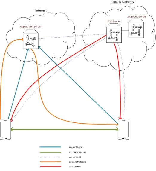
Figure 3.1 depicts the workflow in proposed architecture: (1) User authenticates with Content Register server in the usual way, by visiting to website or using a dedicated application, e.g. Facebook or any other social network could be used as P2P application server. Using an existing social network as content register allows all the publish/search operations with content to automatically obtain users’ social context, e.g., share proximal content only with friends. (2) UE runs a software client, connecting to D2D server in its network, and authorizes it to update P2P application server with necessary information, to allow other users to request pub-lished content via appropriate D2D server. At this point, system ensures that UE system account indeed has access to the corresponding Content Register account. (3) Using functions provided by P2P application, the users can search for any other D2D ready content shared with them. Or they can publish new content, and post their intent to engage in proximal D2D connections with other users. (4) When one of the peers uses hyper-reference from Content Register, it is passed to D2D client software which subscribes UE to D2D server, and the latter resolves content location into actual D2D link-layer connection details. (5) D2D server keeps track of peers’ location and instructs them to start using D2D link, when appropriate conditions are met. When P2P data exchange starts, Content Register is no longer involved. Communications channel is monitored by D2D server and adjusted accordingly to network state, as observed from the core and from UEs. As credentials and direct link parameters are derived by the network, devices themselves need no additional authorization or any direct contact prior to data transfer. Also, when transfer is complete and D2D link is dismantled, the devices are still unaware of each other’s actual identity. This feature allows to further build anonymous sharing services, which are not possible in systems, where devices have to broadcast their presence to detect peers.
Suggested approach resulted in a system with several features:
• The system inherits community tested security and access models from P2P application server. D2D service users can shape access policies for their content to be visible only by certain peers. This implies that in order to be able to even locate the content, an eavesdropper would require to break into P2P application server, resulting in an extra security layer before access to the content itself. Also, while using a publicly and anonymously shared content,
3.2. Network assistance in D2D communications 28 P2P Data Transfer Content Metadata D2D Control Authentication Location Service Internet Cellular Network Account Login Application Server D2D Server
Figure 3.1 Assisted D2D connection establishment via D2D server
a peer does not obtain information about which user exactly is serving it, or what other services are shared by the same UE.
• There is no need for UEs to take the burden of peer discovery, by sending and listening to broadcast requests. UEs can rely on the cellular network to instruct them, when it is suitable to start D2D radio interface and with which parameters. This is utterly important, as keeping D2D interface active can consume significant amount of energy even in case when device does not need to send or receive data.
• The network can provide temporary link layer addresses to users, thus allevi-ating the need to reveal their actual IDs to each other. Devices do not need
3.3. Implementing traffic offloading prototype 29
to publish their actual IDs for discovery or connection setup.
• Network operator can monitor traffic rates and quality of service on network-assisted D2D connections. Even though it is not possible to monitor link states directly, the network can establish a control loop with UE to report and adjust transmission rates and QoS. Having this information, the network can plan and coordinate with existing infrastructure to properly allocate radio resources.
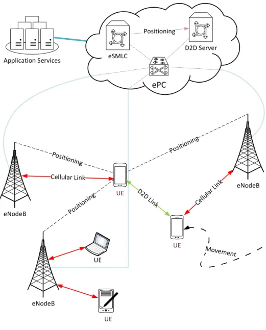
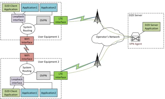
Suggested architecture of network-assisted D2D is easily integrated into existing 3GPP LTE deployment [31]. Figure 3.2 shows the architecture of the integrated system. Only one new entity has to be added to operator’s core – the D2D server. Such placement also allows D2D server to receive information on UE location from eSMLC and to effectively interact with other entities on the Internet.
3.3
Implementing traffic offloading prototype
Within proof of concept implementation, the author of this work was responsible for making required changes to UE operating system, elaborating offloading algorithm based on IP routing, setting up and maintaining infrastructure to run prototype components, and implementing UE side of the prototype. Next subsections elaborate on implementation of these prototype components.
3.3.1
Android networking subsystem
Android, as a Linux-based system1, allows to have simultaneous connections over
more than one radio interface. Once LTE and WiFi connections are active, mobile device has two directly connected networks and one default gateway to send traffic outside of these networks. In this state, it is possible to reach other peer on WFD link only when destination address in IP packet header is WFD address of the peer, and source address is the one of originating mobile device. Also, WFD link uses private address range that is not reachable through anything else than WFD link; once the link is disconnected, the peer becomes unreachable. For the suggested D2D architecture, a device would be required to be able to reach peer’s public IP address on LTE interface through WFD link.
3.3. Implementing traffic offloading prototype 30 eNodeB eNodeB eNodeB UE UE UE ePC eSMLC D2D Server Positioning Application Services UE
3.3. Implementing traffic offloading prototype 31
One of the goals was to create a solution that would be transparent for already existing applications, and this way ease adoption of the technology. For this reason, modifications at the physical layer are not desirable, as it is tightly coupled with radio interface driver. The same applies to Link layer – implementing new functionality there would make the solution vendor-specific. Since existing applications heavily rely on existing transport layer protocols, modifications in transport layer are also not considered. On the other hand, system offers various tools to make changes in IP layer (or Network layer). This would allow to leave underlying radio interfaces as-is, and would enable application developers to use same routines to obtain network access as before. IP addresses are in a way bound to the physical interfaces, but selection process is made without direct interaction with interfaces. This would allow us to create an interface independent solution without modifications of upper layers.
The default configuration of an Android system allows to have routes with multiple gateways, but one of them is inserted into routing table with lower cost than the others. This way no load-balancing is performed and only one route is used. In case of WiFi link and LTE link, or cellular link in general, the route through LTE gateway is preferred for the Internet connectivity because WiFi link and, especially, WFD do not guarantee Internet connectivity at all. Therefore, changing cost of default route would cause unreachability of the Internet for all applications in the mobile device.
3.3.2
Traffic offloading based on routing
The proposed solution is based on allowing mobile device to route IP traffic as usual, and then inject more specific routes for particular peer into routing table. As Android system is based on Linux kernel, it is possible to enable routing functions by modifying the value of system variable net.ipv4.conf. all .forwarding from 0 to 1. After this change, Android mobile device gains capabilities of a generic router, known from computer networks. This way, mobile device can forward packets from one interface to another. The interesting point to note here is that it allows to send IP packets with source address being LTE interface public IP address and destination address being peer’s WFD private IP address, and IP layer of Android system will send them through WiFi interface.
3.3. Implementing traffic offloading prototype 32
to be solved. The first issue arises with application use of network sockets. When an application needs network connectivity, it requests the service from operating system using sockets API, and operating system chooses to use one of the avail-able IP addresses as source address. Source IP address, source transport layer port, destination IP and destination port must remain the same throughout communi-cation, which cannot be guaranteed in case session is bound to WiFi interface IP addresses, because interface can be disabled at any moment. Another issue is with routing private networks through operator’s infrastructure – if a session is bound to WFD’s private IPs it cannot be switched to LTE interface because the operator’s infrastructure prohibits routing packets to this private IP range.
As a workaround for prototype demonstration, a set of OpenVPN tunnels has been elaborated from devices to an anchor point in the network infrastructure, thus allow-ing routallow-ing of private networks through operator’s core. In a real world deployment, however, this would not be necessary, as operator could set up internal routing ac-cording to D2D link networks, issued by D2D server. Also, the system creates an
overlay GRE tunnel bound to loopback interfaces on the devices. Loopback
in-terface is meant to be a constant anchor point for applications, and only overlay
tunnel endpoints will be rerouted, ensuring that session IP addresses remain the same all the time, regardless ofunderlay interfaces used, and thus providing service continuity.
Since only communication with one particular peer needs to be offloaded, a route can be inserted into routing table stating that just the peer’s loopback IP address is reachable through peer’s WFD private IP address. Insertion is performed by the command ip route add PEER_LOOPBACK_IP/32 via PEER_WFD_IP. Once this command is accepted by IP routing layer of Android, all traffic with destination IP address PEER_LOOPBACK_IP will be forwarded to WFD interface and this
way overlay tunnel traffic will be sent over WFD.
The insertion and removal is performed by management application that is running in the background. Both actions are invoked upon a corresponding command from D2D server, but route removal can additionally rely on local channel quality mea-surements. Within this implementation, the only channel quality metric considered is the RSSI. When reaching a particular threshold in RSSI, route can be inserted or removed, thus selecting D2D or infrastructure channels, and reaching even higher threshold can trigger complete link disband.
3.3. Implementing traffic offloading prototype 33
This injection of specific routes into routing table does not have to be performed symmetrically on both devices participating in D2D offloading. Also, route injection scheme is not limited to be used only with a single peer.
3.3.3