QoE-Assured 4K HTTP Live Streaming via
Transient Segment Holding at Mobile Edge
Chang Ge,
Member, IEEE,
Ning Wang,
Senior Member, IEEE,
Wei Koong Chai,
Member, IEEE,
Hermann Hellwagner,
Senior Member, IEEE
Abstract—HTTP-based live streaming has become increasingly popular in recent years, and more users have started generating 4K live streams from their devices (e.g., mobile phones) through social-media service providers like Facebook or YouTube. If the audience is located far from a live stream source across the global Internet, TCP throughput becomes substantially suboptimal due to slow-start and congestion control mechanisms. This is especially the case when the end-to-end content delivery path involves radio access network (RAN) at the last mile. As a result, the data rate perceived by a mobile receiver may not meet the high requirement of 4K video streams, which causes deteriorated Quality-of-Experience (QoE). In this paper, we propose a scheme named Edge-based Transient Holding of Live sEgment (ETHLE), which addresses the issue above by performing context-aware transient holding of video segments at the mobile edge with virtualized content caching capability. Through holding the minimum number of live video segments at the mobile edge cache in a context-aware manner, the ETHLE scheme is able to achieve seamless 4K live streaming experiences across the global Internet by eliminating buffering and substantially reducing initial startup delay and live stream latency. It has been deployed as a virtual network function at an LTE-A network, and its performance has been evaluated using real live stream sources that are distributed around the world. The significance of this paper is that by leveraging virtualized caching resources at the mobile edge, we address the conventional transport-layer bottleneck and enable QoE-assured Internet-wide live streaming services with high data rate requirements.
Index Terms—HTTP live streaming, mobile edge computing, network function virtualization, quality of experience, video caching
I. INTRODUCTION
As the 5G era is fast approaching, so is the landscape of ultra-high quality Internet video streaming applications. More users are now generating 4K live streams directly from their devices through social-media service providers (SMSP) such as Facebook, YouTube or Twitch. Immersive video streaming applications that involve virtual reality (VR) or augmented
This work was supported by the CONCERT (EP/L018683/1) Project under the CHIST-ERA Program (EPSRC/FWF funded) and the EPSRC KCN (EP/L026120/1) Project.
Chang Ge and Ning Wang are with 5GIC, Institute for Communication Systems, University of Surrey, Guildford, United Kingdom, GU2 7XH (E-mail:{C.Ge, N.Wang}@surrey.ac.uk).
Wei Koong Chai is with the Department of Computing and Informatics, Bournemouth University, Dorset, United Kingdom, BH12 5BB (E-mail: [email protected]).
Hermann Hellwagner is with the Institute of Information Technol-ogy, Alpen-Adria-Universitat Klagenfurt, Klagenfurt 9020, Austria (E-mail: [email protected]).
Color versions of one or more of the figures in this paper are available online at http://ieeexplore.ieee.org.
Digital Object Identifier:
reality (AR) content are also becoming more popular, where these contents can be streamed through social networks across the Internet. These applications not only require much higher video quality in terms of resolution and data rate than conven-tional 2D streams; they also set more stringent requirements on receivers’ Quality-of-Experience (QoE). For example, in a VR streaming session where the receiver wears a head-mounted display, the video quality must be above a certain threshold to avoid motion sickness caused by blurry pictures. Furthermore, receivers are generally less tolerant of QoE deteriorating events such as buffering when watching live.
It has become common practice for SMSPs to rely on content delivery networks (CDNs) to distribute user-generated content such as live streams. The benefit is that, once the streamed content becomes available at a local CDN server’s cache, the receivers will be able to access it locally without resorting to the remote live video source. However, the first group of receivers that join the stream will experience cache misses since the content has not yet been cached and needs to be retrieved from the live source over the public Internet. If a live stream is of broadcasting nature with millions of receivers, according to statistics by Facebook [1], around 1.8% of them (which can still be a significant number) will have to stream from the original source due to cache misses. Furthermore, if a live stream is of more private nature (e.g., with only friends watching) and the receivers are very sparsely distributed across the Internet, they are much more likely to experience cache misses at their local CDN servers and hence have to stream directly from the remote live source.
HTTP live streaming typically uses TCP as its underlying protocol. In the scenario where a receiver is located geograph-ically far away from a live stream’s source, TCP is known to experience suboptimal throughput over network paths with long round-trip time (RTT) due to e.g., slow-start and con-gestion control. This is especially the case when the end-to-end (E2E) content delivery path involves combined radio access network (RAN) and long-latency backhaul (including the public Internet) [2]. In this scenario, even if the RAN has adequate bandwidth resources, the E2E video quality still cannot be guaranteed due to the TCP bottleneck. Such an issue at the transport layer is conventionally circumvented through deploying storage capability at the mobile edge to compen-sate poor TCP performance via caching and/or prefetching [2]. While such techniques work well for video-on-demand applications, they have distinct limitations for supporting live streaming, especially if video segments are not even produced yet at the video source. This is particularly the case for
those receivers who suffer from cache misses even with CDN support (as mentioned in the previous paragraph). Another option is to deploy split TCP proxies at the mobile edge to improve transport-layer performance. However, besides issues such as false ACKs which may lead to video frame drops, most importantly, TCP proxies work on a per-flow basis and can incur significant and continuous computational overhead at the mobile edge due to coping with a large number of concurrent live user-generated streaming sessions [3].
In this paper, we propose a policy-driven context-aware QoE assurance scheme named Edge-based Transient Holding of Live sEgment (ETHLE), which addresses the issues above at the application layer. Such a scheme is deployed at the mobile edge within the mobile network operator (MNO) infrastructure as a virtual network function (VNF) calledETHLE edge, and it is operated and owned by stakeholders such as SMSP or CDN operators who rent virtualized computation and storage resources from the MNO, so that the E2E content security and privacy can be retained. The ETHLE edge’s objective is to enable QoE-assured live streaming at the global Internet scale (subject to RAN conditions), where QoE assurance means a) guaranteed 4K video quality; b) no buffering is experienced by the receiver; and c) the live stream latency and initial waiting time are minimal subject to a) and b). Note that the ETHLE edge assures the QoE of live streaming receivers regardless of their distance to the live source, even for the ones who get cache misses in the conventional CDN-based streaming scenario.
In a nutshell, during a live streaming session, the receiver relies on periodically requesting the stream manifest’s content to gain knowledge on up-to-date content availability at the live source. When all requests for video segments and manifest files are handled by the ETHLE edge, if it “holds back” the availability of some segments from the receiver, the receiver will be given the “false” impression on the live video source’s production progress and hence requests segments that were produced a small while ago (depending on the number and length of the held segments). Here, the distinct research challenge is how to define a set of segment holding policies in a context-aware manner, such that receivers’ QoE can be assured at global scale while maintaining the live stream latency at a minimal level by holding the minimal number of segments. Note that although transient segment holding may incur minor extra live stream latency, it is needed to eliminate all buffering events and the unexpected latency introduced by them. Otherwise, without such a technique, the accumulated live stream latency caused by buffering events will substantially exceed the deterministic latency introduced by segment holding (as we will show in Section V).
In order to enable transient holding, the ETHLE edge collects multi-dimensional context information at the mobile edge. These include backhaul context (E2E latency), stream context (bitrates and segment length) and RAN context (mo-bile receivers’ signal strength). The backhaul and stream context are relatively stable and do not require real-time monitoring, and the RAN context is already monitored by the MNO’s radio network information service (RNIS) in today’s practice [4] and is simply passed on to the ETHLE edge.
Therefore, it requires minimal monitoring overhead.
The ETHLE scheme contains an enhanced reverse HTTP proxy (namelyETHLE proxy) with caching capability, which breaks the E2E content delivery path into two parts, where the first part mainly consists of the RAN, and the second part contains the backhaul (including the public Internet). Such an approach not only brings improved and more predictable TCP performance on both parts; it also enables the transient segment holding operations at the mobile edge. Furthermore, because it operates at the application layer, it does not have conventional TCP proxies’ issues such as frame drops caused by false ACKs. It also realizes emulated application-layer multicast (see more in Section III-C), which means for each live stream, it only originates one flow from the live source regardless of the number of its receivers. As we will show in Section V, the QoE metrics of initial startup delay, buffering and live stream latency are assured at the global Internet scale even with E2E RTT of up to 350ms, which is commonly recognized as the worst-case RTT across the Internet.
The main contributions of this paper are briefly summarized below:
• To the authors’ best knowledge, ETHLE is the first scheme that not only assures 4K live streaming receivers’ QoE at global Internet scale, but also is future-proof by meeting next-generation content applications’ stringent requirements at up to 50Mbps based on our real-world experiments. It can be flexibly deployed as a VNF by an SMSP or CDN operator through renting virtual resources from an MNO, so that even though the content delivery path is broken into two segments, the E2E content secu-rity/privacy is preserved when using HTTPS.
• ETHLE is the first QoE-assurance scheme for live stream-ing that has been comprehensively deployed and evalu-ated in an LTE-A network testbed and by using real video sources that are geographically distributed at different continents around the world (see Section V). These real-word experiment results have also been statistically consistent with our theoretical modeling based on a rep-resentative transport-layer congestion control principle. • We provide practical insights into how to use a
policy-driven segment holding technique to assure live users’ QoE under a variety of real-world network scenarios. Such holding policies, which have been validated through both theoretical modeling and real-world experiments, can be directly adopted by SMSPs or CDN operators to tailor their live streaming operations for the sake of their customers’ QoE assurance.
The remainder of this paper is organized as follows. In Sec-tion II, we describe the related background as well as existing QoE improvement techniques of HTTP streaming applications. The proposed ETHLE system overview is presented in Section III, which includes a high-level functional overview, decision-making process on transient segment holding and application-layer signaling under typical scenarios. In Section IV, we show how to model backhaul throughput when a specific TCP congestion control mechanism is used. We then discuss in Section V the results of experiments performed in an
LTE-A testbed using real live streams that are globally distributed. Section VI concludes the paper.
II. BACKGROUND ANDRELATEDWORK A. HTTP-based Live Streaming
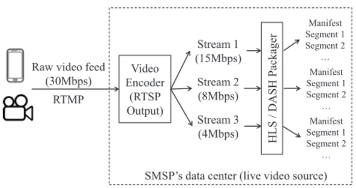
There are a number of HTTP-based live streaming protocols such as Apple HLS (HTTP Live Streaming) [5] and MPEG-DASH (Dynamic Adaptive Streaming over HTTP) [6]. These protocols work in a similar manner, which is illustrated in Figure 1. We use a user-generated live stream as an example here because of this paper’s scope. First, the SMSP user creates a raw live video feed through e.g., the YouTube app on his phone. This raw feed is uploaded to YouTube’s data center via e.g., RTMP (Real-Time Messaging Protocol), where it is encoded and compressed into multiple RTSP (Real-Time Streaming Protocol) streams in real time with different bitrates. Each RTSP stream is then periodically packaged into a series of media segments, whose information is kept up-to-date in a manifest file that is regularly updated.
When a receiver starts watching a live stream, it first re-quests the stream’s manifest via HTTP. The receiver then reads the available segments and bitrates in the stream and picks one to start with. Afterwards, the receiver periodically requests the subsequent video segments as well as the manifest to check if any new entry has been produced at the source. During this process, the receiver is able to switch to any video quality that is available in the manifest on a per-segment basis. The quality switching criteria vary among different implementations and depend on the specific adaptation algorithm that is adopted, which is generally based on the receiver-perceived throughput and/or video buffer.
B. Generic QoE Improvement Techniques of HTTP Streaming
There are many well-defined QoE metrics for HTTP stream-ing receivers, which have been comprehensively studied in [7] and [8]. The most common ones include initial startup delay, buffering frequency and duration, overall video quality and switching between qualities. These metrics apply to both on-demand and live streaming. Furthermore, for live streaming receivers, there is the additional metric of live stream latency, which indicates how far is the receiver’s playback behind the video source’s production progress. It is discussed in [9] that abruptly downgrading video quality during playback would significantly deteriorate QoE. Also, it is shown in [10] that when streaming a monoscopic or stereoscopic 360◦ video, visual discomfort on the viewers’ eyes are mainly caused by decreased video quality as well as buffering.
Generally, the common practice to avoid buffering is to perform video quality adaptation, where a number of well-known algorithms such as FESTIVE [11], PANDA [12] and BOLA [13] have been proposed in this context. However, in the RAN+backhaul scenario that this paper focuses on, the poor E2E TCP throughput means downgrading video quality is inevitable from time to time, which would cause deteriorated QoE. Therefore, in next-generation 4K VR streaming applica-tions, the video quality must be maintained at the 4K threshold, which means quality adaptation needs to be either limited
Raw video feed (30Mbps) RTMP Stream 1 (15Mbps) Stream 2 (8Mbps) Stream 3 (4Mbps) HLS / DA SH Packag er Video Encoder (RTSP Output) Manifest Segment 1 Segment 2 … Manifest Segment 1 Segment 2 … Manifest Segment 1 Segment 2 …
SMSP’s data center (live video source)
Fig. 1: User-generated HTTP-based live stream lifecycle (video bitrates are for illustration only)
or disabled. Another common practice to improve QoE is to cache popular content at the mobile edge [14] [15] [16] and to prefetch video segments on-the-fly at the receiver’s device [17] or at the mobile edge [2] [18] [19]. However, such techniques can only be applied to on-demand video applications, because live video segments cannot be cached or prefetched beforehand either at the client or at the mobile edge as they are produced on-the-fly. Therefore, they are outside this paper’s scope.
C. QoE Improvement Techniques of HTTP Live Streaming
In the literature of improving QoE specifically for HTTP live streaming receivers, the related work can be generally categorized into two types. The first type involves quality adaptation or real-time transcoding to avoid buffering. In [20], the authors evaluated a number of typical throughput-driven and buffer-driven adaptation algorithms in a real live stream-ing trace-driven study, which revealed different algorithms’ tradeoffs on QoE. The authors in [21] proposed an adapta-tion technique for MPEG-DASH live streaming that works through enabling a “tracker” on the receiver’s device, which shares control information among receivers to help adaptation decisions. In [22], a real-time server-based transcoding scheme for HLS live streaming is proposed, in which the server keeps tracking the receivers’ real-time download throughput and adjusts the bitrate of the HLS segments that are served to the receivers. However, these schemes all achieve improved QoE through quality adaptation which, as discussed earlier, may cause visual discomfort to receivers.
The second type focuses on reducing live stream latency. In [23], the authors propose to reduce DASH segment length to as low as 1s, and use the HTTP/2 server push technique to avoid the excessive request overhead caused by short segments. However, it is shown that when using 1s segments, server push itself does not introduce any benefit in live stream latency. In [24], the authors further reduced the segment length to as low as 0.1s. They designed an SDN controller to prioritize video traffic and hence reduce buffering. However, it is not clear what was the network characteristic that the experiments were based on. In [25], the authors studied the live streaming QoE in terms of initial startup delay, buffering and quality switches. The emulation was carried out using measured LTE throughput in Belgium and included an artificial delay of up
to 400ms. It was first shown that segment length should be maintained above 0.5s to avoid excessive encoding overhead when using HEVC. HTTP/2 server push was also shown to reduce buffering and initial delay. However, the results also showed that simply using HTTP/2 is still unable to eliminate buffering under 300ms RTT.
It is important to note that no prior work in the HTTP live streaming literature has examined the TCP performance issue that is caused by mixing RAN and long-distance backhaul in the E2E content delivery path over the global Internet. Therefore, our work is the first of its kind to address this issue. As we will show in Section V through extensive real-world experiments, regardless of how far the video source is located from the live streaming receiver, the proposed ETHLE scheme is always able to eliminate buffering and minimize initial startup delay and live stream latency while guaranteeing 4K video quality.
III. ETHLE SYSTEMOVERVIEW
At the mobile network edge in the MNO infrastructure, some computing and storage resource can be virtualized and leased to e.g., an SMSP or CDN operator1. Here, we envisage that an SMSP or CDN operator rents such virtualized resources from the MNO and deploys the proposed ETHLE scheme. When a content producer wants to produce a live stream that can be shared with remote audiences through the SMSP, the approach that is illustrated in Figure 1 is followed. In this section, we describe how the ETHLE scheme handles remote live receivers’ requests and assures their QoE.
A. Functional Overview
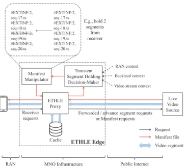
A high-level functional overview of the ETHLE edge (i.e., the VNF that contains the ETHLE scheme, as well as its supporting virtual resources) is presented in Figure 2. The key strategy of ETHLE is to break the conventional E2E content delivery path into two parts containing the RAN and the backhaul respectively, which further enables transient segment holding operations at the mobile edge, through which the ETHLE edge is able to make sure receivers can always get local access to live segments in time. Note that the split content delivery path approach above does not incur any third-party security issue, because the ETHLE edge is still owned and operated by the SMSP thanks to virtualization.
The core function of the ETHLE edge is an enhanced HTTP reverse proxy that is located between the two split content delivery path segments. This proxy, which has content storage capability, is responsible for handling all incoming video requests from receivers. More specifically, depending on the type of the request it receives, it performs different actions as follows.
At the beginning of each streaming session, the first request that the ETHLE proxy receives from a receiver is always for the stream’s manifest file. Upon receiving such a request, the
1If an SMSP uses a CDN, then the CDN operator can rent such virtual
resources at the mobile edge. Otherwise the SMSP can directly rent virtual resources from the MNO without involving a CDN operator. In the rest of the paper, we do not differentiate between these two cases.
ETHLE Edge ETHLE Proxy Transient Segment Holding Decision-Maker Manifest Manipulator Live Video Source Cache Backhaul context Video stream context
Request Manifest file Video segment Forwarded / advance segment requests
or Manifest requests Receiver
requests
RAN MNO Infrastructure Public Internet
#EXTINF:2, seq-17.ts #EXTINF:2, seq-18.ts #EXTINF:2, seq-19.ts #EXTINF:2, seq-20.ts #EXTINF:2, seq-17.ts #EXTINF:2, seq-18.ts #EXTINF:2, seq-19.ts #EXTINF:2, seq-20.ts E.g., hold 2 segments from receiver RAN context
Fig. 2: ETHLE system overview
proxy always forwards it to the live video source. Afterwards, when the proxy retrieves the file from the video source, it collects information on the following context:
• Backhaul conditioninformation between the source and the proxy. The key metric here isRTTbecause it governs the TCP slow-start performance and is used to model the backhaul TCP throughput (denoted by thbh, whose modeling details are further discussed in Section IV). It is calculated at the beginning of each live streaming session by analyzing the timestamps of corresponding TCP SEQ and ACK packets, which is done through a customized version of tcpdump at the proxy. Note that since the backhaul latency is typically stable (as we will show in Section V), such calculation only needs to be performed once for each live video source with a fixed network location.
• RAN condition information which includes each re-ceiver’s signal strength (e.g., RSRP, RSRQ and RSSI in LTE, and RSSI in WiFi) and mobility pattern (e.g., fast, slow, static). This knowledge is obtained from the MNO’s RNIS and is used to estimate the RAN throughput the receiver is expected to get (denoted by thran); this estimation process is further explained in Section III-B. • Video stream informationwhich includes each stream’s
bitrate and segment length (in seconds) (denoted by
bseg and lseg respectively). This information is used to determine the minimum requirement of backhaul and RAN throughput in order for the receiver to receive a video segment in time. Note that Constant Bit Rate (CBR) encoding is commonly used in live streaming [26] [27] [28], which results in similar sizes of all segments in a stream.
Taking as input the three types of context knowledge above, upon receiving an incoming request for a live streaming session, the ETHLE edge makes a real-time decision on the optimal (x, wherex≥0) number of video segments that need
to be held back from the receiver to assure QoE. The rationale behind transient segment holding is as follows. In HTTP live streaming, a receiver periodically requests the manifest because from its perspective, the manifest always contains the most up-to-date information on segment availability at the live video source. Recall that all requests for manifests and video segments are handled by the ETHLE edge. Therefore, if the ETHLE edge holds xsegments back from the receiver (as illustrated in Figure 2)2, the receiver will be given the impression that those segments have not been produced at the source yet, who will begin a session requesting segments that were produced a little while ago (depending on x and segment length). This creates an opportunity for the ETHLE edge to open multiple (up to x) parallel (but transient) TCP connections towards the live source and download the held segments before they are requested by the receiver. Hence, the ETHLE edge can ensure that the receiver has local access to the subsequent video segments. Note that these multiple TCP connections do not need to be maintained throughout the streaming session, because as soon as the ETHLE edge’s local content availability isxsegments ahead of the receiver’s request progress, the ETHLE edge can maintain the lead by downloading one segment in advance at a time using one TCP connection. This is because a receiver’s request pattern is very regular in a live streaming session. Also note that the ETHLE edge operates at application layer and is agnostic to underlying transport layer techniques. For example, while it can benefit from advanced techniques such as Multi-Path TCP, it does not necessarily rely on them to achieve QoE assurance.
In Section III-B, we use a single-receiver unicast scenario as a simple example to explain the ETHLE edge’s decision-making flow when determining the optimal number of seg-ments that need to be transiently held.
B. Single-Receiver Unicast Scenario
For each live streaming session, the ETHLE edge follows a two-step sequential decision-making process as follows.
First, the ETHLE edge decides whether the performance of hold-0 (i.e., x = 0 and no segment is held) is sufficient to assure receiver’s QoE, which means guaranteed 4K quality and no buffering during streaming. Note that hold-0 is still different from the E2E content delivery mode, as it splits the E2E content delivery path into two segments. In this case, each video segment’s download time, which is the time duration between when the receiver sends the request for a segment and when the receiver fully receives that segment, needs to meet the following inequality in order for hold-0 to satisfy the QoE assurance criteria above:
sseg
thbh
+ sseg
thran
≤lseg (1)
where sseg refers to a video segment’s size (in bytes), and the left side represents the aggregated transmission time of the
2In practice, there can be different ways to remove a video segment from
a manifest depending on the streaming protocol. What is illustrated in Figure 2 shows how it is done in Apple HLS protocol. In MPEG-DASH, it can be done by manipulating the availabilityStartTime attribute in the manifest. Either way, the receiver will be given the false impression on the live source’s production progress.
video segment over the backhaul and the RAN respectively. In order to estimate thran of a user in an LTE network, our approach is similar to the one in [29] which considers the user’s RSRP, RSRQ and RSSI in a linear function. Further-more, we also take into account the number of active users in the cell. Due to the fluctuating nature of RAN, the ETHLE edge estimates each user’s thran relatively frequently (e.g., upon receiving each request from a user).
If inequality (1) holds, no segment needs to be transiently held to assure QoE because each segment’s download time is shorter than its length and hence can be downloaded before it is consumed by the receiver. Therefore, in this case, the ETHLE edge simply needs to break the E2E content delivery path and act as a standard HTTP reverse proxy.
If inequality (1) does not hold, transient segment holding is necessary to assure QoE subject to the RAN throughput meeting the 4K stream’s bitrate requirement. In this case, the objective becomes identifying:
argmin x sseg thbh·x ≤lseg (x= 1,2, . . .) (2) subject to: thran> bseg (3)
As described in Section III-A, holding x segments means the ETHLE edge “hides” their availability at the live video source from the receiver, hence creating opportunity for itself to download them utilizing parallel TCP connections from the live source. This means the effective backhaul throughput is
thbh·x. In inequality (2), the minimal value ofxis identified such that the effective backhaul throughput is higher than the video stream’s bitrate requirement. This is because when holdingxsegments from the receiver, an additional live stream latency ofx·lsegis incurred, and such extra latency overhead should be minimized to avoid QoE deterioration. It is worth mentioning that the ETHLE edge’s operator may also impose an upper limit on the value ofxto prevent excessive number of parallel TCP connections from being opened.
Note that constraint (3), which specifies that the RAN throughput must be higher than the video stream’s bitrate, also needs to be met in order for hold-xto work. Otherwise, even if the ETHLE edge is able to download video segments beforehand, the receiver still cannot download the video seg-ments over the RAN in time. In other words, the usefulness of the ETHLE scheme is to enable E2E QoE assurance in 4K live streaming subject to adequate RAN resources, and to avoid the underlying transport-layer protocol from becoming the bottleneck. Therefore, if constraint (3) cannot be met due to low RAN throughput, the ETHLE scheme is not applicable any more, and there are two possible actions that the ETHLE proxy can take. First, the ETHLE proxy can send an HTTP 301 Redirect response to the receiver and instruct it to send all further requests to the live video source. In this case, the conventional E2E adaptation logic at the receiver will work on its own. Second, the ETHLE proxy can still download the originally-requested high-quality video segment from the source, and perform local video transcoding to match different
Receiver ETHLE Edge
Live Video Source
Receiver-initiated ETHLE edge-initiated
19
20
m Event where segment mhas been produced
at live video source
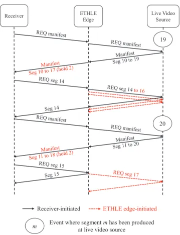
Fig. 3: Single-receiver unicast sequence diagram: two seg-ments are held by the ETHLE edge
receivers’ RAN throughput. In either case, there are many existing work in the literature (see Section II). In this section, we assume that constraint (3) always holds.
After the optimal value ofxis calculated in inequality (2), the ETHLE proxy hides the last x segments’ availability by manipulating the manifest and serves its modified version to the receiver. After receiving the manifest, the receiver chooses a segment to request based on the manifest’s content. For example, if a manifest states that segments m to m+k are available, the receiver will, by default, start by requesting segment m+k −3 as recommended in [5]. This creates the opportunity for the ETHLE edge to perform two tasks in parallel. First, it handles the request by acting as a reverse proxy. If the segment is already available locally, it serves the file immediately. Otherwise, it retrieves the file from the live source over the backhaul and serves it afterwards. Second, if x segments were held back earlier, it downloads those segments by opening x parallel TCP connections towards the video source. Note that the value of x is optimized to ensure that the ETHLE edge can get ahead of the receiver’s streaming progress just in time. In other words, through these parallel TCP connections, the ETHLE edge is able to ensure local availability of subsequent video segments before they are requested by receivers.
The above process is illustrated in Figure 3, where the ETHLE edge holds two segments from the receiver, which means it is able to download segments 15 and 16 in addition to
the requested segment 14. This enables the edge’s local content availability to stay ahead of the receiver’s streaming progress by two segments, which makes sure the receiver has local access to all subsequent segments. This would not have been possible without the segment holding functionality, because the ETHLE edge cannot download any segment (in addition to the requested one) that has not yet been produced at the video source. Note that the two parallel TCP connections that are used to download segments 15 and 16 do not need to be kept open, since starting from segment 17, only one connection is needed for the ETHLE edge to maintain its lead over the receiver’s progress.
C. Emulated Multicast in Multi-Receiver Scenarios
So far, we have described how the ETHLE edge responds to a single receiver’s requests and performs transient segment holding. We now explain how multiple receivers’ requests are handled when they are consuming the same live stream under the same ETHLE edge’s coverage. Note that the following procedures are performed on a per-stream basis.
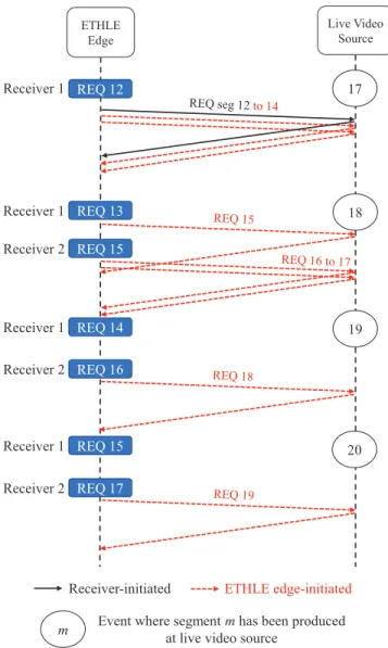
When multiple receivers watch the same live stream, their watching progress are typically similar. However, when seg-ment length is short (e.g., 2s or 4s), their progress may differ by one to two segments due to e.g., minor clock drift on the receivers’ devices etc. If the later-joined receiver’s progress is behind the earlier one’s progress, the ETHLE edge can directly serve video segments that have already been downloaded for the earlier receiver. On the other hand, it is also possible that the later receiver is ahead of the earlier one. Such a situation is illustrated in Figure 4 where two segments are transiently held. In the beginning, receiver 1 begins by requesting segment 12, and the ETHLE edge opens two extra TCP connections and downloads segments 12 to 14 in parallel from the live source. Afterwards, when the ETHLE edge is downloading segment 15 to stay two segments ahead of receiver 1 (who has just requested segment 13), receiver 2 joins the stream and begins by requesting segment 15. While receiver 2 waits for the ETHLE edge to finish downloading segment 15 from the live source, the ETHLE edge immediately starts downloading both segments 16 and 17 to stay two segments ahead of receiver 2. Afterwards, both receivers have local content access at the ETHLE edge. Therefore, the ETHLE edge always stays
x segments ahead of the receiver with the most advanced
watching progress of a live stream.
In a mobile network, receivers may experience dynamic RAN signal strength, which means the values of thran for receivers of a live stream can vary significantly. Recall from inequality (1) that thran and thbh jointly determine whether hold-0 is able to assure a receiver’s QoE. Also recall from inequality (2) that if hold-0 is unable to assure a receiver’s QoE, the optimal hold-x is determined by thbh only, which applies on a per-stream basis and does not vary among receivers with different RAN conditions. Therefore, for each live stream, the ETHLE edge creates two policy groups where one is for receivers whosethran andthbh are high enough to make hold-0 the optimal scheme, and the other one is for other receivers with lower thran who need hold-x to assure their
ETHLE Edge Live Video Source 17 18 REQ 12 Receiver 1 19 20 REQ 13 REQ 15 REQ 14 REQ 16 REQ 15 REQ 17 Receiver 1 Receiver 1 Receiver 1 Receiver 2 Receiver 2 Receiver 2
Receiver-initiated ETHLE edge-initiated
m Event where segment mhas been produced
at live video source
Fig. 4: Two-receiver multicast sequence diagram: two seg-ments are held by the ETHLE edge
QoE. When a new receiver joins a stream, the ETHLE edge evaluates inequality (1) based on the receiver’s thran and the stream’s thbh, and assigns it to one of the two groups. Cor-respondingly, the ETHLE edge operates two coexisting sets of transient segment holding policies (i.e., 0 and
hold-x), which means receivers in each group will receive slightly different versions of the manifest and hence have different watching progress. Note that such asynchronous progress among receivers watching the same live stream is already a common phenomenon when using E2E TCP connections. Nevertheless, the receivers in the hold-x group will always get local content access, since the segments they request will have already been downloaded for any receiver in the hold-0 group earlier.
For mobile receivers, their RAN conditions often fluctuate (sometimes significantly) due to e.g., mobility or building obstacles between receivers and base station. Due to this reason, for each live streaming session, the ETHLE edge regularly evaluates inequality (1) either in a time-driven or
in a request-driven manner. If the RAN condition of a hold-0 group’s receiver worsens and inequality (1) no longer holds, which means hold-0 is no longer able to assure its QoE, it will be moved into the hold-x group to avoid buffering. On the other hand, a hold-x group’s receiver cannot be moved into the hold-0 group, because it would cause xsegments to be skipped during the streaming, which will be perceived as a negative experience by the receiver. Also note that for receivers whose thran does not meet constraint (3), as described in the previous subsection, they will not be subject to any transient segment holding and can use either video quality adaptation or edge-based transcoding techniques.
With the operations described above, it can be inferred that regardless of the number of receivers who are watching a live stream through an ETHLE edge, it always creates only one stream between itself and the live video source. Therefore, it effectively achieves an emulated multicast between the receivers and the source, which reduces the backhaul traffic volume. Furthermore, as we will show in Section V, it sig-nificantly improves the receiver-perceived segment download time without incurring the expensive computational overhead as split TCP proxies do.
IV. BACKHAULTHROUGHPUTMODELING
As presented in Section III-B, the backhaul throughputthbh of a live stream is a crucial parameter for the ETHLE edge to determine the optimal number of transiently held segments. In this section, we discuss the estimation of thbh based on backhaul RTT and video stream information. We focus on using the recently-proposed BBR (Bottleneck-Bandwidth and Round-trip latency) as the TCP congestion control mechanism [30]. Due to its superior performance over long-distance public Internet when compared to other TCP variants such as CUBIC, as well as the fact that it has been deployed on all YouTube servers and is well making its way into a standard [31], we use BBR as an upper bound on TCP performance in video streaming applications3.
BBR attempts to send data based on the bandwidth-delay product (BDP) of the network path by estimating the bottle-neck bandwidth,bwmax, and the RTT of the path,rttmin. We denote the estimation via measurements of these parameters as bwmaxc andrttminc respectively.
Based on [30], we have the following:
c
bwmax= max(rate(t)); ∀t∈[T−WB, T] (4) where WB determines the measurement window size and is typically set between 6s and 10s andrate(t)is the measured delivery rate based on received acknowledgments and
c
rttmin= min(rtt(t)); ∀t∈[T−WR, T] (5) where WR is the measurement window size of RTT and is typically set to 10s. Note that
3Modeling the detailed behavior of BBR is of course not the focus of
this work, especially when the protocol itself is currently still under constant update and patching. Our methodology here is modular however and can benefit from more accurate models in the future when BBR specifications have been fully standardized.
c
rttmin =rttprop+ min(η(t)) (6) where rttprop is the propagation delay andη(t)accounts for additional delay caused by queues along the path and other protocol induced latency such as delayed acknowledgement strategy, acknowledgement aggregation, etc.
The BDP can then be estimated as follows:
d
bdp=bwcmax×rttcmin (7)
A BBR connection goes through different states over its lifetime.
• STARTUP: When a connection is first started, a BBR connection is in the STARTUP state which roughly corresponds to the slow-start phase of window-based TCP implementations (e.g., CUBIC). In this state, BBR probes for more bandwidth by increasing the sending rate (controlled by pacing gain) with a factor of2/ln(2)for an estimatedrttcmin and exits this state when a “plateau” is reached (e.g., no more additional bandwidth is found after three RTTs). The exponential search ofSTARTUP finds the BDP inlog2(bdp)RTTs.
• DRAIN: Due to the fact that STARTUP leads to expo-nential growth of in-flight packets, it also creates a queue at its end. As such, the connection enters theDRAINstate after STARTUP to reduce the queue (the current BBR specification sets this at2×bwmax×rttmin by setting the sending rate to ln(2)/2).
• ProbeBW: At steady state, BBR enters the ProbeBW state where it cycles its sending rate at eight phases using
pacing gain = {1.25,0.75,1,1,1,1,1,1} where each phase lasts for an rttcmin. As such, in the long run, at steady state, the connection sends at pacing gain= 1. • ProbeRTT: Periodically, BBR enters the ProbeRTT
state to estimate current RTT. This is done by limiting the in-flight data to four packets formax(rtt,200ms)before returning to its previous state.
To estimate thbh, we first assume that the path conditions
remain stable over the entire segment delivery period since (1) the individual video segment size is relatively small (a video segment can usually be completely delivered within 10-20 RTTs based on our Internet-wide measurements with a variety of scenarios) and (2) the backhaul RTT is highly stable (see our real measurements in Figure 8). We further assume there is no loss. Therefore, our modeled throughput is an optimistic higher estimation. We also note that, unlike current variants of loss-based congestion control mechanisms that reduce drastically send rates when losses are detected, BBR does not explicitly react directly to packet losses but rather implicitly via measurement of the BDP.
Let mss be the maximum TCP segment size in bytes. Then, we model the number of bytes that is transferred in theSTARTUPstate for the delivery of a segment (denoted as
thstartup) using the geometric progression of the sending rate and obtain: thstartup≈ mss(1−(ln(2)2 )dstartup) 1− 2 ln(2) (8)
where dstartup refers to the duration spent in the STARTUP phase. Transforming Equation (8) and we get:
dstartup≈log 2 ln(2) 1−thstartup(1− 2 ln(2)) mss (9) Considering that BDP over the backhaul is generally stable, we can then approximate the transmission duration of the entire video segmentdseg as follows:
dseg≈dstartup+
(sseg−thstartup)
bwmax
(10) wheresseg refers to the video segment’s size. Assuming that the backhaul TCP connection maintains the transmission at the bottleneck bandwidth rate, the overall backhaul throughput can then be written as:
thbh=
sseg
dseg
. (11)
The outcome of Equation (11) is used as input when deter-mining the optimalxas described in Section III. Specifically, by combining Equations (2), (10) and (11), the objective in (2) becomes: argmin x x≥ 1 lseg dstartup+ (sseg−thstartup) bwmax (12) As we will show in Table III of Section V, our estimated values of boththbh and the optimal number of held segments
xhighly match the actual measured results.
V. PERFORMANCEEVALUATION
In this section, we systematically evaluate the performance of the ETHLE scheme in a variety of real-world scenarios at global scale.
A. Experiment Setup
A receiver with an HLS client is connected to the Internet through an LTE-A (3GPP Rel.14) testbed network infrastruc-ture that is hosted by 5GIC at University of Surrey, UK. We use a Chromium browser (version 61) running on a Linux PC with hls.js4 v0.8.5 as the HLS client, and the PC is connected to the LTE-A network through USB tethering on a Google Pixel phone. The RAN is operated by a Huawei lampsite at LTE Band 41 (2545 - 2575MHz) and offers a maximum downlink throughput of 112Mbps [32]. The ETHLE edge is implemented by customizing and extending a Jetty5web server in Java. It realizes the context monitoring, request handling and transient segment holding functions as presented in Sections
4https://github.com/video-dev/hls.js/ 5http://eclipse.org/jetty/
TABLE I: Video Segment Size
Segment Length
Bitrate 2s 4s 10s
15Mbps 3.7MB 7.2MB 18.3MB
0 50 100 Throughput (Mbps) 0 0.2 0.4 0.6 0.8 1 F(x) (a) US West 0 50 100 Throughput (Mbps) 0 0.2 0.4 0.6 0.8 1 F(x) (b) Japan 0 50 100 Throughput (Mbps) 0 0.2 0.4 0.6 0.8 1 F(x) (c) Australia 0 50 100 Throughput (Mbps) 0 0.2 0.4 0.6 0.8 1 F(x) (d) India 15Mbps 2s 15Mbps 4s 15Mbps 10s 50Mbps 2s 50Mbps 4s 50Mbps 10s
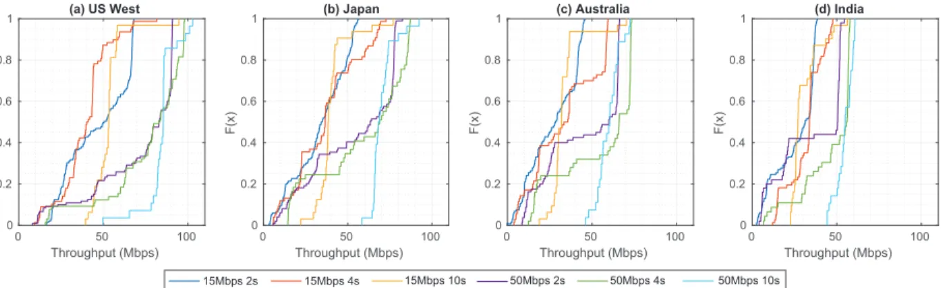
Fig. 5: E2E scheme’s overall receiver-perceived throughput performance: CDF results
0 100 200 300 Time (s) 0 50 100 150 200
LTE air interface RTT (ms)
(a) Idle 15% 50% Idle 15% 50% Cell Load 0 50 100 150 200 (b)
Fig. 6: LTE air interface latency measurement results vs. cell load
III and IV. It is deployed as a VNF at the Packet Gateway (P-GW) of the LTE core network.
In order to create scenarios where the live video source is located at different locations, we adopt the following approach. First, we create four virtual machines (VM) instances through Google Compute Engine (part of Google Cloud Platform) at four different location scenarios (US West, Japan, Australia and India) with a variety of representative RTTs towards UK (137ms, 224ms, 302ms and 334ms respectively). Each VM runs Ubuntu 16.04 with kernel 4.10.0-38 and contains a single-core CPU and 4GB RAM. Note that the backhaul between the P-GW and these VMs are completely public with no reserved network resource. BBR is used as the TCP congestion control mechanism on all video sources. Then, to produce a live video feed, we use a Nokia OZO+ camera which outputs 360◦ monoscopic 4K 30FPS video at about 3Gbps. The raw video feed is then sent to a Matrox Maevex 6100 encoder card via an SDI cable, where it is encoded into two RTSP streams with bitrates of approximately 15Mbps and 50Mbps respectively using CBR. For both streams, key frames are inserted every two seconds. At a local video production server, each RTSP stream is packaged into three HLS streams with segment lengths of 2s, 4s and 10s respectively. Therefore, our experiments are based on a total of 6 stream scenarios. For each HLS stream, as soon as a new segment is generated, it is uploaded (with the latest manifest file) to all VMs so that they can act as live video sources. The size of each video
segment in these 6 streams is shown in Table I. For the sake of consistency and fairness, all streaming sessions are cut off at exactly five minutes after the first request is issued. Note that for each location/stream scenario, we repeat the experiment for 3 times during different time of the day at around 9AM, 2PM and 8PM (UK time). Since the observed results do not vary significantly among different experiment time, we show the results of experiments performed in the morning only in this section.
B. Performance Metrics
We evaluate the performance of two types of schemes: end-to-end (E2E) and hold-x. In the E2E scheme, the HLS is unaware of the ETHLE edge’s presence and directly streams video from the sources over the RAN+backhaul path. In the hold-xschemes, the ETHLE edge manipulates the manifest by holding backxsegments from the receiver as presented earlier. Furthermore, we derive the optimalxunder each deployment scenario as described in Section IV. Through the experiment results, we evaluate the optimality of the derived x.
The following QoE metrics are evaluated. Note that we do not evaluate video quality here, because guaranteeing 4K quality is a prerequisite in our case due to application requirements (as explained in Section I), which means no quality adaptation below 4K is allowed.
• Initial startup delay: how long does the receiver wait before the video starts playing?
• Buffering: how long does the streaming stall due to low buffer?
• Live stream latency: how far is the receiver behind the video source’s production progress? In this work, we evaluate this metric after the receiver streamed for 5 minutes.
A scheme produces the best QoE among the schemes if it meets the following criteria:
1) It causes no buffering throughout the 5-minute period. 2) It produces the lowest live stream latency among all the
schemes after the 5-minute period.
3) It produces the lowest initial startup delay among all the schemes.
If any criterion produces a tie between multiple schemes, the next criterion in the list will serve as a tie-breaker.
0 100 200 Throughput (Mbps) 0 0.2 0.4 0.6 0.8 1 F(x) (a) US West 0 50 100 150 Throughput (Mbps) 0 0.2 0.4 0.6 0.8 1 F(x) (b) Japan 0 50 100 Throughput (Mbps) 0 0.2 0.4 0.6 0.8 1 F(x) (c) Australia 0 20 40 60 80 Throughput (Mbps) 0 0.2 0.4 0.6 0.8 1 F(x) (d) India 15Mbps 2s 15Mbps 4s 15Mbps 10s 50Mbps 2s 50Mbps 4s 50Mbps 10s
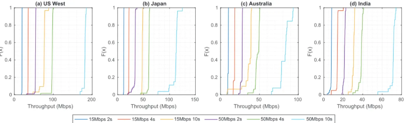
Fig. 7: Hold-0 scheme’s backhaul throughput performance: CDF results
0 100 200 300 Time (s) 100 150 200 250 300 350 RTT Latency (ms) (a) US West Japan Australia India
US West Japan Australia India
100 150 200 250 300 350 (b)
Fig. 8: Backhaul latency measurement results
Furthermore, we also evaluate the following QoS metrics: • Receiver-perceived throughput: the
receiver-experienced download throughput on a per-segment basis. This is measured at the receiver’s device.
• Backhaul throughput: the throughput that the ETHLE edge experiences when downloading each video segment from the video source. This is measured at the ETHLE edge and applies to hold-xscenarios only.
C. QoS Performance of the E2E Scheme
We begin by examining the E2E scheme’s QoS perfor-mance, i.e., receiver-perceived E2E throughput, whose CDF is plotted in Figure 5. The E2E scheme does not involve the ETHLE edge and hence, the content delivery path includes both RAN and backhaul. It is shown that the E2E throughput exhibits significant variation among all scenarios, which is caused by the heavily fluctuating LTE air interface latency under data traffic. Such a phenomenon is a well-known charac-teristic of LTE RAN [33] and is validated by our experiments as shown in Figure 6, which shows that when the small cell is loaded by 50%6, the RAN latency fluctuates between 20ms and 180ms. Such latency fluctuation, when combined with a backhaul with high RTT, has a significant effect on TCP slow-start performance by causing its congestion window to increase at a slower and unpredictable pace. Note that even
6We use iPerf3 as the load generator in this case.
when a persistent HTTP connection is used and the TCP connection is kept alive, the server always restarts the slow-start phase upon sending each video segment to the receiver due to the time interval between requests, which makes the server consider the connection to be idle. Therefore, the RAN latency fluctuation affects all video segment downloads and causes their throughput to vary significantly.
It is also observed in Figure 5 that streams with longer segment lengths experience less fluctuations in E2E through-put. For example, under the Japan scenario, 50Mbps-2s and 50Mbps-10s streams experienced a standard deviation σ of 25.8Mbps and 6.7Mbps in their E2E throughput respectively. This is because as segment size gets larger, their TCP perfor-mance gets more resilient to the fluctuating latency since the slow-start phase becomes less dominant of the throughput.
Another observation is that as the backhaul RTT gets higher, the overall E2E throughput gets lower. Taking the 50Mbps-2s stream as an example, it experienced mean E2E throughputs of 71.2Mbps, 53.6Mbps, 44.8Mbps and 34.9Mbps at US West, Japan, Australia and India respectively. This is because longer RTT means it takes longer for the TCP congestion window to grow in the slow-start phase, which results in lower overall throughput.
D. QoS Performance of the Hold-0 Scheme
We now evaluate the QoS performance (i.e., backhaul throughput) of the Hold-0 scheme, whose CDF is plotted in Figure 7. Note that the backhaul throughput is very similar among all hold-xschemes, so we only plot the results under hold-0 here.
First, it is shown that all stream scenarios experience very stable backhaul throughput among all locations. For example, under the Australia scenario, 15Mbps-2s, 4s and 10s streams’ backhaul throughput had σ of 0.4, 0.7 and 7.7Mbps, and 50Mbps-2s, 4s and 10s streams experiencedσof 1.0, 2.9 and 6.8Mbps respectively. Such performance is due to the stable backhaul latency, which is generally dominated by the network path length and is validated through our measurement results in Figure 8. Since the backhaul we used in our experiments is completely public, there are occasionally mild fluctuations in the TCP throughput. As a result, large file transfers (e.g., 15Mbps-10s and 50Mbps-10s streams) are more likely to
(a) 15Mbps 2s (( + + + /LYH6WUHDP/DWHQF\V (b) 15Mbps 4s (( + + + (c) 15Mbps 10s (( + + + (d) 50Mbps 2s (( + + + (e) 50Mbps 4s (( + + + (f) 50Mbps 10s (( + + + (a) 15Mbps 2s ((+ + + + /LYH6WUHDP/DWHQF\V (b) 15Mbps 4s (( + + + (c) 15Mbps 10s (( + + + (d) 50Mbps 2s ((+ + + + (e) 50Mbps 4s (( + + + (f) 50Mbps 10s (( + + + (a) 15Mbps 2s ((+ + + + /LYH6WUHDP/DWHQF\V (b) 15Mbps 4s (( + + + (c) 15Mbps 10s (( + + + (d) 50Mbps 2s ((+ + + + (e) 50Mbps 4s (( + + + (f) 50Mbps 10s (( + + + (a) 15Mbps 2s ((+ + + + + /LYH6WUHDP/DWHQF\V (b) 15Mbps 4s (( + + + (c) 15Mbps 10s (( + + + (d) 50Mbps 2s ((+ + + + (e) 50Mbps 4s ((+ + + + (f) 50Mbps 10s (( + + +
,QLWLDOVWDUWXSGHOD\ %XIIHULQJGXUDWLRQ +ROG[H[WUDOLYHVWUHDPODWHQF\
86:HVW
-DSDQ
$XVWUDOLD
,QGLD
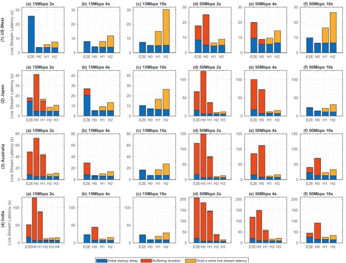
Fig. 9: Live stream latency results, where H0 means hold-0 etc.
experience such fluctuation, which explains the slightly higher variation in their throughput. On the other hand, streams with smaller segment sizes finish each segment download quicker and hence experience less throughput fluctuation.
Furthermore, the negative correlation between the backhaul RTT and throughput is also observed here. These results show that the transfer of the video segments (with sizes of 3.7MB to 61.1MB) are dominated by TCP slow-start performance, which validates our model of TCP backhaul performance in Section IV.
E. QoE Performance Evaluation
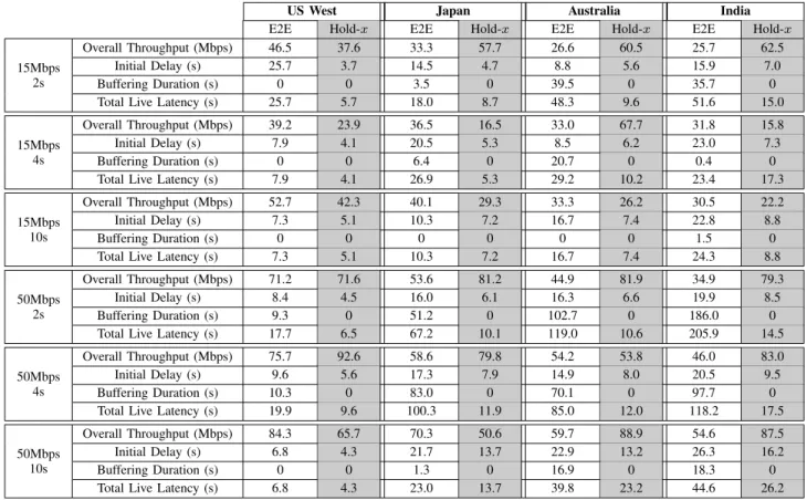
After examining the QoS performance patterns, we now look into the QoE performance of E2E and hold-xschemes where x is up to 4 (depending on specific scenarios). More specifically, all schemes’ live stream latency after 5 minutes of streaming are plotted in Figure 9, which uses stacked bar charts because live stream latency consists of initial startup de-lay, buffering duration and transient segment holding latency. Note that the ranges of the subfigures’ y-axis are grouped on a per-location, per-stream-scenario basis. Furthermore, in Table II, we present the statistical results on the QoE metrics of E2E and each scenario’s optimal hold-xschemes.
The first observation is that among all scenarios, the E2E scheme’s initial startup delay is much higher than any hold-x
scheme’s. This is because TCP slow-start takes longer under the E2E scheme due to the effect of RAN latency fluctuation, long backhaul RTT and packet errors as discussed earlier. Note that the initial startup delay is an important QoE metric as it may cause a receiver to abandon the live stream before it starts. For example, in a mobile network, an initial delay of 10s or 20s will cause around 15% or 35% of users to quit the stream respectively [34]. It can be observed from Table II that each scenario’s optimal hold-x scheme is mostly able to achieve a sub-10s initial delay, while E2E scheme often incurs much higher initial delay of up to 26.3s. Therefore, E2E scheme is unable to assure QoE in any of the scenarios that we have evaluated.
We now examine each of the four location scenarios’ QoE results. Under the US West scenario, hold-0 scheme is able to produce assured QoE for all three 15Mbps streams. No segment needs to be held thanks to the relatively low backhaul RTT, which means the backhaul throughput is much higher than the required 15Mbps, even when considering the effect of slow-start caused by small segment size. Meanwhile, although holding more segments produces higher overall throughput, no further QoE benefit can be introduced. Instead, it introduces
0 25 50 75 100 Throughput (Mbps) 0 0.2 0.4 0.6 0.8 1 F(x) (a) 15Mbps 2s 0 25 50 75 100 Throughput (Mbps) 0 0.2 0.4 0.6 0.8 1 F(x) (b) 15Mbps 4s 0 25 50 75 100 Throughput (Mbps) 0 0.2 0.4 0.6 0.8 1 F(x) (c) 15Mbps 10s 0 25 50 75 100 Throughput (Mbps) 0 0.2 0.4 0.6 0.8 1 F(x) (d) 50Mbps 2s 0 25 50 75 100 Throughput (Mbps) 0 0.2 0.4 0.6 0.8 1 F(x) (e) 50Mbps 4s 0 50 100 150 200 Throughput (Mbps) 0 0.2 0.4 0.6 0.8 1 F(x) (f) 50Mbps 10s 0 25 50 75 100 Throughput (Mbps) 0 0.2 0.4 0.6 0.8 1 F(x) (a) 15Mbps 2s 0 25 50 75 100 Throughput (Mbps) 0 0.2 0.4 0.6 0.8 1 F(x) (b) 15Mbps 4s 0 25 50 75 100 Throughput (Mbps) 0 0.2 0.4 0.6 0.8 1 F(x) (c) 15Mbps 10s 0 25 50 75 100 Throughput (Mbps) 0 0.2 0.4 0.6 0.8 1 F(x) (d) 50Mbps 2s 0 25 50 75 100 Throughput (Mbps) 0 0.2 0.4 0.6 0.8 1 F(x) (e) 50Mbps 4s 0 50 100 150 200 Throughput (Mbps) 0 0.2 0.4 0.6 0.8 1 F(x) (f) 50Mbps 10s 0 25 50 75 100 Throughput (Mbps) 0 0.2 0.4 0.6 0.8 1 F(x) (a) 15Mbps 2s 0 25 50 75 100 Throughput (Mbps) 0 0.2 0.4 0.6 0.8 1 F(x) (b) 15Mbps 4s 0 25 50 75 100 Throughput (Mbps) 0 0.2 0.4 0.6 0.8 1 F(x) (c) 15Mbps 10s 0 25 50 75 100 Throughput (Mbps) 0 0.2 0.4 0.6 0.8 1 F(x) (d) 50Mbps 2s 0 25 50 75 100 Throughput (Mbps) 0 0.2 0.4 0.6 0.8 1 F(x) (e) 50Mbps 4s 0 50 100 150 200 Throughput (Mbps) 0 0.2 0.4 0.6 0.8 1 F(x) (f) 50Mbps 10s 0 25 50 75 100 Throughput (Mbps) 0 0.2 0.4 0.6 0.8 1 F(x) (a) 15Mbps 2s 0 25 50 75 100 Throughput (Mbps) 0 0.2 0.4 0.6 0.8 1 F(x) (b) 15Mbps 4s 0 25 50 75 100 Throughput (Mbps) 0 0.2 0.4 0.6 0.8 1 F(x) (c) 15Mbps 10s 0 25 50 75 100 Throughput (Mbps) 0 0.2 0.4 0.6 0.8 1 F(x) (d) 50Mbps 2s 0 25 50 75 100 Throughput (Mbps) 0 0.2 0.4 0.6 0.8 1 F(x) (e) 50Mbps 4s 0 50 100 150 200 Throughput (Mbps) 0 0.2 0.4 0.6 0.8 1 F(x) (f) 50Mbps 10s
E2E overall throughput Hold-x backhaul throughput Hold-x overall throughput
86:HVW -DSDQ $XVWUDOLD ,QGLD
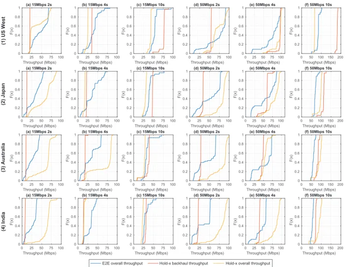
Fig. 10: Per-location per-stream throughput performance: CDF results
additional live stream latency due to segment holding. This means that under relatively low backhaul RTT and video stream bitrate, simply breaking the E2E connection is already able to significantly reduce initial startup delay without caus-ing any buffercaus-ing.
For the 50Mbps streams, hold-1 is the optimal scheme when the segment length is 2s or 4s. Neither E2E nor hold-0 is able to avoid buffering because the segment sizes are still relatively small (12.2MB and 24.4MB), and their throughput occasionally drops below 50Mbps due to slow-start. However, when the segment length is 10s, the segment size (61.1MB) becomes large enough to overcome slow-start and achieves a mean backhaul throughput of 181Mbps. This makes hold-0 the optimal scheme in this case.
Under the Japan scenario, for the 15Mbps-2s stream, hold-0 is no longer able to avoid buffering because the small segment size (3.7MB) causes the backhaul throughput to fall below the required 15Mbps threshold (11.8Mbps on average). As a result, hold-2 is the optimal scheme in this case. For 15Mbps-4s and 10s streams, hold-0 is still the optimal scheme, because their larger segment sizes lead to better slow-start performance and achieve average backhaul throughput of 35.2Mbps and 75.4Mbps respectively. For the 50Mbps streams, 2, hold-1 and hold-0 are required for optimal QoE under the 2s, 4s
and 10s scenarios respectively. Again, this is because as seg-ment size gets larger (12.2MB, 24.4MB and 61.1MB), fewer video segments need to be held back due to higher backhaul throughput (33Mbps, 58.3Mbps and 111Mbps respectively).
The QoE results under the Australia and India scenarios are similar as above. We summarize the optimalxnumber of segments that need to be held in each scenario in Table III. Furthermore, for each scenario, we plot its overall throughput under the E2E scheme as well as its backhaul and overall throughput under the optimal hold-xscheme in Figure 10. The significance of Figure 10 is twofold. First, it shows that the op-timal hold-xscheme’s overall throughput is not always higher than the E2E scheme’s results. In fact, in many scenarios, the hold-xscheme’s mean throughput is lower than the E2E scheme’s. However, the hold-xscheme’s overall throughput is always higher than the video stream’s required bitrate (except for the first one to two segments as the ETHLE edge is gaining its lead over the receiver’s progress). In contrast, a significant portion of the E2E scheme’s throughput results are below the required bitrates due to its fluctuation. Second, it shows that even with stable backhaul throughput, the hold-x scheme’s overall throughput still exhibits some variation, which can only be caused by the RAN latency fluctuation. However, note that its effect on the overall throughput is much weaker under the
TABLE II: Statistics on key performance metrics’ results: E2E vs. optimal hold-xschemes
US West Japan Australia India
E2E Hold-x E2E Hold-x E2E Hold-x E2E Hold-x
15Mbps 2s
Overall Throughput (Mbps) 46.5 37.6 33.3 57.7 26.6 60.5 25.7 62.5
Initial Delay (s) 25.7 3.7 14.5 4.7 8.8 5.6 15.9 7.0
Buffering Duration (s) 0 0 3.5 0 39.5 0 35.7 0
Total Live Latency (s) 25.7 5.7 18.0 8.7 48.3 9.6 51.6 15.0
15Mbps 4s
Overall Throughput (Mbps) 39.2 23.9 36.5 16.5 33.0 67.7 31.8 15.8
Initial Delay (s) 7.9 4.1 20.5 5.3 8.5 6.2 23.0 7.3
Buffering Duration (s) 0 0 6.4 0 20.7 0 0.4 0
Total Live Latency (s) 7.9 4.1 26.9 5.3 29.2 10.2 23.4 17.3
15Mbps 10s
Overall Throughput (Mbps) 52.7 42.3 40.1 29.3 33.3 26.2 30.5 22.2
Initial Delay (s) 7.3 5.1 10.3 7.2 16.7 7.4 22.8 8.8
Buffering Duration (s) 0 0 0 0 0 0 1.5 0
Total Live Latency (s) 7.3 5.1 10.3 7.2 16.7 7.4 24.3 8.8
50Mbps 2s
Overall Throughput (Mbps) 71.2 71.6 53.6 81.2 44.9 81.9 34.9 79.3
Initial Delay (s) 8.4 4.5 16.0 6.1 16.3 6.6 19.9 8.5
Buffering Duration (s) 9.3 0 51.2 0 102.7 0 186.0 0
Total Live Latency (s) 17.7 6.5 67.2 10.1 119.0 10.6 205.9 14.5
50Mbps 4s
Overall Throughput (Mbps) 75.7 92.6 58.6 79.8 54.2 53.8 46.0 83.0
Initial Delay (s) 9.6 5.6 17.3 7.9 14.9 8.0 20.5 9.5
Buffering Duration (s) 10.3 0 83.0 0 70.1 0 97.7 0
Total Live Latency (s) 19.9 9.6 100.3 11.9 85.0 12.0 118.2 17.5
50Mbps 10s
Overall Throughput (Mbps) 84.3 65.7 70.3 50.6 59.7 88.9 54.6 87.5
Initial Delay (s) 6.8 4.3 21.7 13.7 22.9 13.2 26.3 16.2
Buffering Duration (s) 0 0 1.3 0 16.9 0 18.3 0
Total Live Latency (s) 6.8 4.3 23.0 13.7 39.8 23.2 44.6 26.2
hold-xscheme than under the E2E scheme, because the former has isolated the RAN part from its E2E TCP path.
A number of key observations can be made from the optimal number of held segments in Table III. First, under each video stream scenario, more segments need to be held when backhaul RTT gets higher. This is due to the negative correlation between backhaul throughput and RTT.
Second, under the same video bitrate requirement, more segments need to be held as video segment length gets shorter. This is due to the positive correlation between segment size and backhaul throughput.
Third, for video streams with the same segment length, more segmentsmayneed to be held as video bitrate gets higher. This is because although higher bitrate means better TCP slow-start performance, in some cases such performance improvement is not enough to match the higher bitrate requirement.
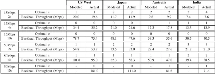
The three observations above provide general guidelines on how the optimal number of held segments is affected by different context, such as backhaul RTT, video bitrate and segment length. However, to actually determine the value of optimal x, we still need to use the modeled backhaul throughput (as described in Section IV) and follow the strategy as presented in Section III. In the next subsection, we validate the accuracy of our modeled backhaul throughput as well as the optimal xthat is derived based on it.
F. Validating Modeled Backhaul Throughput and Derivedx
In Table III, we present the modeled backhaul throughput. Furthermore, we present the optimal x that is derived by
solving inequalities (1) and (2) in Section III-B alongside their actual measured values in the experiments. Note that for each scenario, the measured backhaul throughput results are averaged over all video segment downloads. This does not affect the results’ validity since CBR encoding is used, so all video segments have very similar sizes.
It is shown in the table that among all stream scenarios except the 50Mbps-10s one, the modeled and actual backhaul throughput values are very close, where the differences be-tween the two are in the range of 0Mbps to 6.8Mbps with an average of 1.33Mbps. Furthermore, the optimal x that is derived from the model always matches the actually-measured result with only one exception. For the 15Mbps-2s stream under the India scenario, since there were some fluctuations in the backhaul throughput (that can be observed in Figure 7), the model-derived optimalxis 3 while 4 segments needed to be held to avoid buffering. However, this can be considered to be an extreme case. Recall from Table I that the video segment sizes range between 3.7MB and 24.4MB for the first 5 stream scenarios. The fact that the modeled and actual backhaul TCP performance matches well validates our modeling strategy in Section IV. It also shows that the transfers of files with the sizes above finish before the TCP slow-start phase ends.
On the other hand, for the 50Mbps-10s stream scenario whose segment size is 61.1MB, we observe that there is a relatively large gap (up to 22.3%) between the modeled and actual backhaul throughput. This shows that for video segments with larger sizes, their transfer goes beyond the TCP slow-start phase and enters subsequent stages such as drain. As explained in Section IV, we are currently not yet able to
TABLE III: Statistics on optimal number of held segments and backhaul throughput: modeled vs. measurement results
US West Japan Australia India
Modeled Actual Modeled Actual Modeled Actual Modeled Actual
15Mbps 2s Optimalx 1 1 2 2 2 2 3 4 Backhaul Throughput (Mbps) 20.0 19.6 11.7 11.9 9.6 9.9 7.4 7.6 15Mbps 4s Optimalx 0 0 0 0 1 1 1 1 Backhaul Throughput (Mbps) 34.4 35.2 21.0 21.6 17.2 17.8 13.3 13.9 15Mbps 10s Optimalx 0 0 0 0 0 0 0 0 Backhaul Throughput (Mbps) 78.7 75.4 48.1 47.6 39.3 35.6 30.5 30.5 50Mbps 2s Optimalx 1 1 2 2 2 2 3 3 Backhaul Throughput (Mbps) 54.8 53.7 33.5 33.0 27.4 27.6 21.2 21.0 50Mbps 4s Optimalx 1 1 1 1 1 1 2 2 Backhaul Throughput (Mbps) 101.8 95.0 62.3 58.3 50.9 47.0 39.4 38.5 50Mbps 10s Optimalx - 0 - 0 - 1 - 1 Backhaul Throughput (Mbps) - 181.0 - 111.0 - 81.6 - 71.4
model TCP BBR performance for the phases beyond slow-start due to its being a work-in-progress and lack of specification. Therefore, we omit the relevant results in Table III. However, should such a model become available in the future, it can be easily embedded into our modeling strategy in Section IV which is left as our future work.
VI. CONCLUSION
In this paper, we have proposed a scheme named Edge-based Transient Holding of Live sEgment (ETHLE), which is able to assure 4K live streaming receivers’ QoE at global Internet scale. Specifically, it addresses the issue where TCP experiences poor throughput when the E2E content delivery path involves combined RAN and long-distance backhaul. The ETHLE scheme can be flexibly deployed as a VNF (i.e., ETHLE edge) at the mobile network edge, which breaks the E2E content delivery path into two segments containing the RAN and the backhaul respectively at the application layer. The benefits of such a strategy are threefold. First, it boosts TCP performance on both path segments without incurring the expensive computation overhead that a TCP split proxy has. Second, it enables the ETHLE edge to perform transient segment holding at the mobile edge. Third, it preserves the E2E content privacy/security since the ETHLE edge is owned and operated by the SMSP or CDN operator who rents virtualized computing and storage resources from MNOs. We have also developed a model-based approach to derive the optimal number of video segments that need to be transiently held to assure receivers’ QoE. Specifically, it is derived through modeling the performance of TCP congestion control mechanism’s slow-start phase over the backhaul link, because video segments are relatively small in size, and in most cases their transmission ends before the slow-start phase finishes.
The accuracy of the modeled TCP backhaul performance and the derived optimal x, as well as the ETHLE scheme’s QoE assurance performance are comprehensively evaluated through real-world experiments, which involve an LTE-A testbed infrastructure and live video sources that are deployed at US West, Japan, Australia and India respectively. Experi-ment results show that the proposed ETHLE scheme is capable
of assuring live receivers’ QoE by eliminating buffering and significantly reducing initial startup delay and live stream latency when compared with the conventional E2E scheme. Furthermore, the accuracy of the modeled TCP backhaul throughput and derived optimal x are also validated as they highly match the actual measured results.
ACKNOWLEDGEMENTS
The authors would like to acknowledge the support of University of Surrey’s 5GIC (http://www.surrey.ac.uk/5gic) members for this work. The authors would also like to thank Richard Bradbury, who leads a team at BBC Research & Development investigating new technologies for Internet content distribution. His feedback on the work described and his review comments were incorporated into the paper.
REFERENCES
[1] Facebook, “Under the hood: Broadcasting live video to millions.” [On-line]. Available: https://code.facebook.com/posts/1653074404941839/ under-the-hood-broadcasting-live-video-to-millions/
[2] C. Ge, N. Wang, G. Foster, and M. Wilson, “Toward QoE-assured 4K video-on-demand delivery through mobile edge virtualization with adaptive prefetching,”IEEE Transactions on Multimedia, vol. 19, no. 10, pp. 2222–2237, Oct 2017.
[3] J. Border, M. Kojo, J. Griner, G. Montenegro, and Z. Shelby, “Performance Enhancing Proxies Intended to Mitigate Link-Related Degradations,” IETF, RFC 3135, June 2001. [Online]. Available: https://tools.ietf.org/html/rfc3135
[4] “Mobile Edge Computing - a key technology towards 5G.” [Online]. Available: http://www.etsi.org/images/files/ETSIWhitePapers/ etsi wp11 mec a key technology towards 5g.pdf
[5] R. Pantos and W. May, “HTTP Live Streaming,” IETF, RFC 8216, August 2017. [Online]. Available: https://tools.ietf.org/html/rfc8216 [6] ISO, “ISO/IEC 23009-1:2014 dynamic adaptive streaming over HTTP
(DASH) – Part 1: Media presentation description and segment formats.” [Online]. Available: http://www.iso.org/iso/home/store/catalogue ics/ catalogue detail ics.htm?csnumber=65274
[7] M. Seufert, S. Egger, M. Slanina, T. Zinner, T. Hosfeld, and P. Tran-Gia, “A survey on quality of experience of HTTP adaptive streaming,”IEEE Communications Surveys & Tutorials, vol. 17, no. 1, pp. 469–492, First Quarter 2015.
[8] Y. Liu, S. Dey, F. Ulupinar, M. Luby, and Y. Mao, “Deriving and validating user experience model for DASH video streaming,” IEEE Transactions on Broadcasting, vol. 61, no. 4, pp. 651–665, Dec 2015. [9] S. Tavakoli, S. Egger, M. Seufert, R. Schatz, K. Brunnstrm, and
N. Garca, “Perceptual quality of HTTP adaptive streaming strategies: Cross-experimental analysis of multi-laboratory and crowdsourced sub-jective studies,” IEEE Journal on Selected Areas in Communications, vol. 34, no. 8, pp. 2141–2153, Aug 2016.