Annales UMCS Informatica AI 2 (2004) 173-182 Annales UMCS Informatica Lublin-Polonia Sectio AI http://www.annales.umcs.lublin.pl/
Validation of reactive embedded systems against
specification requirements
Joanna Strug, Stanis
ł
aw Deniziak, Krzysztof Sapiecha
∗ Cracow University of Technology, Warszawska 24, 31-155 Kraków, PolandAbstract
In this paper a method of automatic generation of test scenarios for verification of specification requirements (temporal and functional) for reactive embedded systems is presented.
1. Introduction
The aim of design-validation is to check whether or not specification requirements (functional and temporal) imposed on a system are met [1,2].
Most of recently proposed techniques of design-validation use formal verification methods, like model checking [1,3] and theorem proving [4]. These methods typically use automata based models [4] of a system and temporal logic (TL) [5] in order to express the required temporal properties. However, temporal properties, which may be expressed in this way are limited to safety and liveness [6,3]. Some extensions of TL can capture time properties more precisely. In Timed CTL [1,2] time-bounded versions of each time operators are introduced. Real-time logic (RTL) [6] includes special predicates, which relate events that happen in a system with the time they occur. The duration calculus [7] add operators to access intervals. On the basis of these extensions it is possible to verify certain design properties including temporal requirements.
In [8] there are proposed two proof methodologies corresponding to two specification styles of real-time properties. A system is modeled as a real-time transitional one. Time properties are expressed in time-bounded logic or by explicit reference to a current time through a special clock variable. A deductive proof is then conducted to show the consistency with the specification.
The formal verification methods are limited to small and medium size designs or are restricted to some subproblems. For large systems, simulation-based validation techniques are still most popular [9]. The main problem here is to
∗ Corresponding author: e-mail address: pesapiec@cyf-kr.edu.pl
develop a set of input stimuli giving high validation accuracy. Some efficient methods of automatic generation of test scenarios to validate a system against functional requirements have already been developed [10,11]. However, there are no such satisfactory methods as far as temporal requirements are concerned. Moreover there are no efficient methods for validation of both types of specification requirements.
The aim of this paper is to present a method of automatic generation of test scenarios for validation of embedded systems [12] against temporal and functional requirements. Test scenarios are derived from system requirements and are then applied to a model or a prototype of the system. Each test scenario consists of verification sequence (sequence of stimuli to be applied to system inputs) and the expected responses which are then compared with those generated by the system while simulating. Main features of the proposed method are described in sections 2 and 3. Section 4 includes short comparison, considerations and conclusions.
2. Embedded system model
It is assumed that a designer starts with gathering functional and temporal requirements (temporal constraints) for a system. These requirements are usually described in a textual form, but it is assumed that each of the requirements has a unique identifier. Manual translation to more formal specification (e.g. SCR [13]) is then performed and a suitable model of the functional requirements is automatically developed (as described in [10]).
A model of an embedded system S is defined as a couple S = (T, G), where T
is a set of tasks1 that should be executed by the system and G = (V, E) is a directed graph representing its functional requirements. Each functional requirement or its separated part (if any) and each task have unique identifiers denoted by RId and TId correspondingly. Execution time of a task is fixed and data-independent. V is a finite set of nodes. Nodes belonging to V correspond to stable states of the system. Values of state variables determine the state of S. A single node denoted by v0 distinguished from V represents initial state of the system. E is a set of edges. Each edge belonging to E represents transition between a given pair of nodes. Edges are labeled with stimuli, responses (if any is generated), requirements and tasks identifiers.
Graph G can be a cyclic or an acyclic one. It depends on the system. Multiple edges are also enabled (in order to represent different causes of transition between the same states).
Safety Injection System (SIS) for nuclear reactor [10] serves as an example for our method. Functional requirements for the system are given in Table 1. Each of the requirements is supplemented with identifiers of tasks which are
1 Tasks are extracted from a task graph [14,15].
executed to meet the given requirement or its part. On this basis a model of the system is developed (Figure 1). The state variables and their admissible values are: WP (P – permitted water pressure, TL – water pressure below the threshold
LOW), Overridden (T – if Block has been asserted and F – if Reset has been asserted), TrefCnt (asserts counting of time, may have the values of 0, 1 and 2) and SJ (Off – if the valve is closed and On – if the valve is opened).
Table 1. Functional requirements for SIS
RId Description
R1 The system shall assert SafetyInjection valve T1). when WaterPres falls below LOW ( opening a
R2
(a) A The system shall be blocked (blocking T3) in response to Block being asserted while
Reset is not asserted and WaterPres is below LOW, and shall remain blocked until either (c) Reset is asserted or (b) WaterPres crosses LOW from a larger to smaller value
(unblocking T4 and setting TrefCnt to zero T6).
R3 Once SafetyInjection or WaterPres is asserted, it shall remain asserted until the system becomes blocked becomes greater than or equal to LOW (closing a valve T2). R4 counting (increasing TrefCnt T5) and (b) automatically unblock (T4 and T6) itself after When the system is blocked and WaterPres is less than LOW, the system shall (a) start
the third timing reference event is sensed on input Tref.
Fig. 1. Functional requirements graph for SIS
It is typical for reactive systems that they interact continuously with the environment in which they operate. Hence, constraints imposed on the system by the environment (external requirements) must be considered. These constraints include input signals frequency, time separation between signals occurrences on different inputs or inputs and outputs, etc [14].
There may also exist time constraints expressing desired time relation between a system and its environment and between different tasks (some tasks or devices may require specific timing). In order to represent these constraints (internal requirements) minimal and maximal delays may be introduced. They define the amount of time allowed for execution of particular task(s). The minimal time delay determines the first possible moment of the time at which the execution of specified task(s) may be completed, whereas maximal time delay determines the time at which it must be completed. A temporal constraint is violated if the execution of task(s) is completed to early or to late. A unique Constraint Identifier (CId) is associated with each temporal requirement.
Temporal requirements imposed on SIS are given in Table 2 where: @A denotes A as an initial event for execution of tasks, ’ and ” indicate paths associated with different tasks and () and {} denote constraint associated with a particular path and marked subsets of nodes respectively. Requirement described in the second row of Table 2 belong to the requirements associated with a group of paths. The remaining requirements are associated with particular tasks.
Table 2. Temporal requirements for SIS
Cid Tmin tmax Description Notation
1 0 1
Time required for opening a valve (SJ=On) when water pressure falls below the allowed threshold (@WaterPres <
LOW). (1,2)
2 0 0,5
Time required for transition to a proper state (WP=P) when water pressure rise above the allowed threshold
(@WaterPres >= LOW).
{2,3,4,5}=> {1}
3 0 2 open the valve (@Reset=On, SJ=On) when water pressure is Time required for manual unblocking the system and to lower than the allowed threshold (WP=TL).
(3,2)’, (4,2), (5,2)
4 0 1,5 asserted (@Block=On) and water pressure is lower than the Time required for closing a valve (SJ=Off) when Block is threshold (WP=TL).
(2,3)
5 0 3,0
Time required for automatic unblocking and to open a valve (SJ=On) when the system have been blocked and three
timing references have been sensed on input Tref. (3,2)’’ 3. Verification sequences
A solution applied here is based on the concept of critical paths. A path Sij
from node vi to node vj in graph G is defined as a sequence of edges <ei,i+1,ei+1,I+2, ...,ej-1,j>, where ek,k+1 belonging to E denotes an edge between nodes vk, vk+1 belonging to V. Each path, to which a temporal constraint is
associated, is called critical path [16,17].
Generation of verification sequences for all critical paths results in exhaustive verification of all temporal constraints, thus reductions are necessary. In our approach a reduced set of critical paths is selected and then evaluated to check if the paths cover also all functional requirements (paths should include edges labeled with all RId).The set is then updated with one-edge paths for missing RId
if necessary.
Each critical path determines a subset of tasks, which should be executed in a time given by a temporal constraint. A constraint may be imposed on a path representing given (in specification) subset of tasks. This situation allows existence of multiple paths (between different pairs of nodes), but all of them represent the same subset of tasks. An example of such a constraint is presented in Figure 2. For task T1 three critical paths (<e1,2>, <e3,4> and <e5,4>) are
determined.
Fig. 2. Constraint imposed on task T1
Fig. 3. Constraint imposed on transition between nodes 2 and 4
A constraint may be also imposed on a transition between given states of the system (referred to as source and target nodes respectively). Hence all paths between these nodes are critical ones and may represent different subsets of tasks. Such a situation is shown in Figure 3. Paths <e2,3,e3,4>, <e2,5,e5,4> and <e2,4> are all critical ones.
Design-validation based on exhaustive verification sequences is always valid. On the contrary, design-validation based on reduced verification sequences might lead to optimistic conclusions.
The goal of our work is to generate a reduced but still comprehensive set of test scenarios for a system. To this aim some assumptions are taken. These are the following:
1. each temporal constraint requires at least one verification sequence to be verified, but all tasks associated with any constraint have to be checked, 2. execution time of each of the tasks belonging to T is fixed and it does not
depend upon the way the task is started. Such assumption does not hold for general purpose systems but it usually holds for embedded ones. However, it is not true for tasks, whose execution time is data dependent. Then the validation results are only approximated ones, but they can be improved if we assume WCET (Worst Case Execution Time) for maximum delays or/and BCET (Best Case Execution Time) for minimal delays.
On the basis of these assumptions, the number of paths to be generated and verified can be considerably limited. However, for some systems this might be too optimistic. Temporal correctness of execution of tasks is checked rather than of a particular critical path. Nevertheless, there is at least one verification sequence covering each temporal constraint in the generated set.
The selection of critical paths to be generated and combined is based on comparison of subsets of tasks associated with these paths. Let two critical paths
P and P*, and two sets of tasks T and T*, associated with P and P* respectively, be given. Path P covers P*, if T* is a subset of T.
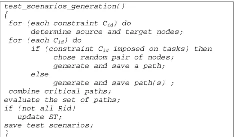
In Figure 4 draft and main procedures of the algorithm of generation of test scenarios are presented.
test_scenarios_generation() {
for (each constraint Cid) do
determine source and target nodes; for (each Cid) do
if (constraint Cid imposed on tasks) then
chose random pair of nodes; generate and save a path; else
generate and save path(s) ; combine critical paths;
evaluate the set of paths; if (not all Rid)
update ST;
save test scenarios; }
Fig. 4. An algorithm of generation of test scenarios
At first source and target nodes for possible (not yet generated) paths are determined. Next, for each constraint paths are selected and generated according to the following rules:
1. If a constraint is imposed on a subset of tasks then verification of any path containing these tasks is sufficient (they cover each other). The choice of the path to be generated is not of primary importance and may be random. For example, path <e1,2> in Figure 2 may be chosen. The remaining paths associated with the constraint are those rejected. Reductions preformed at this step are the most effective, because a number of paths may be significantly limited without their generation.
2. If only source and target nodes are specified, paths are generated and associated with them subsets of tasks are determined and compared (covered paths are rejected). The minimal subset of paths associated with a given constraint consists of paths representing execution of different subsets of tasks. In Figure 3 path <e2,4> representing task T3 and
<e2,3,e3,4> representing tasks T1 and T2 belong to the minimal set for the
constraint. Path <e2,5,e5,4> may be dropped as a covered one.
The execution of this step produces a reduced set of critical paths. It is the smallest set that includes critical paths representing all different subsets of tasks. Two path generation algorithms are used. The first one searches for all possible paths between specified nodes. The second one makes it possible to determine edges belonging to a path if tasks to be executed are specified. Both algorithms use similar techniques. During the generation of critical paths a Paths Tree (PT) is built and accepted nodes are added to it. The acceptance functions prevent us from exploring already visited nodes. Combination of the generated paths allows for further reductions. Minimal coverage of generated paths is reached in a similar way as in [10], e.g. a Scenarios Tree (ST) is built and paths are added to it. In the next step the set is evaluated to determine whether all functional requirements are covered by paths from this set or not. It relies on checking if all
RId are represented by labels of edges in ST. In the case that not all RId have been found, a procedure similar to that in [10] is started. It explores the state space of G and adds one-edge path labeled with missing RId to ST. The algorithm of test scenarios generation ends after saving stimuli and responses labeling edges of ST.
In Table 3 the final result of the application of the algorithm to SIS is given ((PId) S
ij (CId) denotes a critical path; Path Identifier (PId) is introduced to
distinguish paths generated for CId time constraint). At the beginning ten critical paths were founded. Next, four of them were rejected during the generation process and another one during combination of the remaining paths. Because these paths did not cover the R2c requirement one extra edge was added to satisfy this requirement. Finally, a set of four test scenarios was produced
(Table 3). Experimentally calculated verification quality QV2[17] for verification sequences from this set equals 1. It means that all errors, temporal as well as functional, randomly injected into the model were correctly detected.
Table 3. Reduced set of test scenarios for SIS
No Test scenarios (Pid)Sst(Cid)
1 WaterPres < LOW/SafetyInjection = On WaterPres >=LOW/SafetyInjection = Off
1S1,2(1), 2S2,1(2) 2
WaterPres < LOW/SafetyInjection = On Block = On/SafetyInjection = Off
Tref/ WaterPres >= LOW/ 1S1,2(1), 1S2,3(4), 3S4,1(2), 3 WaterPres < LOW/SafetyInjection = On Block = On/SafetyInjection = Off Reset = On/ SafetyInjection = On
1S1,2(1), 1S2,3(4), 1S3,2(3),
4
WaterPres < LOW/SafetyInjection = On Block = On/SafetyInjection = Off
Tref/ Tref/ Tref /SafetyInjection = On 1S1,2(1), 1S2,3(4), 1S5,2(5)
The exhaustive set of test scenarios used for experimental evaluation of the reduced one consists of eight scenarios. The total length of all verification sequences belonging to the exhaustive set equals 31 stimuli, whereas the length of verification sequences in the reduced set is equal to only 14 stimuli.
4. Conclusions
Actually an embedded system designer may choose one of the following approaches to verification specification requirements: time budget-based [14], formal [1-4,8] and simulation-based verification [10,11].
Some knowledge about time budgets for execution of tasks can help the designer to keep correctness of the system under control throughout the whole design flow. Though, it does not guarantee that any design error will occur. Moreover, usually calculation really true budgets is not easy.
Formal verification techniques require the system specification requirements to be described in a form of logical expressions (formulas). It is assumed that the PRES+ model [1,2] is generated from an implementation of a system and it reflects exactly time relations in the real system. Such model may represent data and control flow, as well as concurrency. This is an advantage with respect to
2 Verification quality (Q
V) is defined as follows: Qv = 1-C0/C, where C0 is the number of optimistic verification conclusions (GO instead of NOGO), and C is the total number of verifications [17].
other approaches. But to start the verification one requires an access to exact execution times for tasks and thus may be conducted very late in the design flow.
Test scenarios generation for simulation-based verification does not require any time information and can be performed very early in the design process. Test scenarios can be reused for validation of the system (or its model) on multiple levels of design description and multiple design alternatives.
In the paper a simulation-based method for validation of embedded systems against specification requirements is presented. Test scenarios obtained with the help of the method can be used for verification both, functional and temporal requirements. The method is easy to use in practice and verification sequences are short. Automating test scenarios generation makes the method fast and flexible.
Our solution is inspired by the method presented in [10] which addresses only the problem of functional validation. We extended this method with the possibility of verification of temporal requirements. Distinguishing of tasks gives us an insight into internal behavior of the system and helps for appropriate selection of paths to be verified.
Although, the method should usually provide good validation results there are some problems to be remembered. Reductions which are performed to get a set of paths and of test scenarios assume rejection of covered paths. In some situations (covered path represents fewer tasks than the covering one) it may lead to undetected violation of a temporal constraint, because the covering paths can compensate for the time. It must be also taken into consideration that if execution time of each task is not constant then the verification sequences are only rough ones.
References
[1] Cortes L.A., Eles P., Peng Z., Formal Coverification of Embedded Systems using Model Checking, Proc. EUROMICRO, (2000).
[2] Cortes L.A., Eles P., Peng Z., Verification of Embedded Systems using a Petri Net based Representation, Proc. of the 13th ISSS, (2000).
[3] Varea M., Al-Hashimi B., Dual Transitions Petri Net based Modelling Technique for Embedded Systems Specification, Proc. of the 4th DATE Conference, (2001).
[4] Alur R., Henzinger T.A., Ho P.-H., Automatic Symbolic Verification of Embedded Systems, IEEE Trans. Software Engineering, (1996).
[5] Bellini P., Mattolini R., Nesi P., Temporal Logics for Real-Time System Specification, ACM Computer Surveys, (2000).
[6] Edwards S., Lavagno L., Lee E.A., Sangiovanni-Vincentelli A., Design of Embedded Systems: Formal Models, Validation, and Synthesis, Proc. of the IEEE, (1997).
[7] Chaochen Z., Duration calculus, a logical approach to real-time system, Lecture Notes in Computer Science, (1999).
[8] Henzinger T., Manna Z., Pnueli A., Temporal Proof Methodologies for Timed Transitional Systems, Proc. of the 18th ACM Symposium on Principles of Programming Languages, (1991).
[9] Ziegenbein D., Jersak M., Richter K., Ernst R., Breaking Down Complexity for Reliable System-Level Timing Validation, Proc. of the 9th IEEE Electronic Design Process Workshop, (2002).
[10] Cunning S., Rozenblit J.W., Automating Test Case Generation for Requirements Specification for Real-time Embedded Systems, Proc. of the 1999 IEEE SMC’99, (1999).
[11] Lajolo M., Lavagno L., Rebaudengo M., Automatic Test Bench Generation for Simulation-based Validation, Proc. of the 8th CODES, (2000).
[12] Turley J., Embedded Processors by the Numbers, Embedded Systems Programming, (1999). [13] Heitmeyer, C., Kirby, J., Labaw, B., The SCR Method for Formally Specifying, Verifying and
Validating Requirements: Tool Support, Proc. of the International Conference on Software Engineering, (1997).
[14] Dasdan A., Ramanathan D., Gupta R.K., Rate Derivation and Its Applications to Reactive, Real-time Embedded Systems, Proc. of the 35th Design Automation Conf., (1998).
[15] Dick R.P., Rhodes D.L., Wolf W., TGFF: Task Graphs for Free, Proc. of the Int Workshop Hardware/Software Codesign CODES/CASHE’98, (1998).
[16] Strug J., Deniziak S., Sapiecha K., An Application of Test Scenarios for Verification of Time Constraints in Embedded Systems, RUC’2003, (2003), in Polish.
[17] Strug J., Deniziak S., Sapiecha K., Validation of Reactive Embedded Systems against Temporal Requirements, ECBS, 2004, Brno, accepted for presentation.