April 20, 2015
Dear Prospective Vendor,
The RFP is a comprehensive document that outlines the City’s requirements. The City’s assumption is each vendor is uniquely qualified and proficient, in the communications field. Vendors should review the RFP and respond accordingly, understanding each vendor will have a different solution for meeting the City’s requirements. The City expects vendors to act responsibly and present their solution in a manner that makes their solution(s) the best choice, for the City of Conway.
The RFP contains certain language with the assumption that the City will be joining the state of Arkansas system (AWIN). Vendors should provide (2) two separate proposals. First, a proposal that reflects a system that is completely integrated with the State of Arkansas system, along with pros and cons. Second, a proposal that reflects a standalone system, with pros and cons. The standalone system should include all the equipment, at the City’s RF site, should the City decide to join AWIN, requiring minimal cost to the City of Conway. Both proposals should include any additional cost that would be required to meet the coverage requirements in this RFP, i.e. additional tower sites.
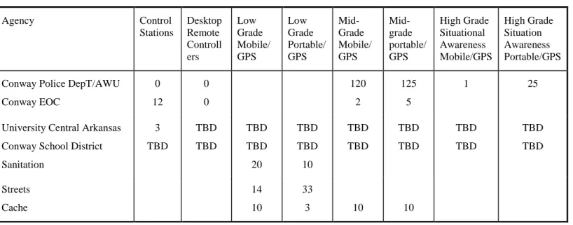
With this project, other entities are expected to share in the cost of a new system. The response to the RFP should be detailed. The City needs a comprehensive, individual cost breakdown for each entity, to determine each entities fair share of radios, dispatch consoles, maintenance cost, etc...
The quantity of mobile and handheld radios, as well as other devices, may change. The bid should be such that the City can increase or decrease the number of radios or devices and easily determine the cost. Dispatch workstation costs should be such that the City can easily determine the cost of workstations for the different entities, City of Conway (12), University of Central Arkansas (3), Antenna Tower, Communications Shelter and associated equipment should be such that the City can easily determine the cost of specific items such as the shelter, UPS, and HVAC.
FirstNet
FirstNet will ensure the establishment of the first nationwide public safety broadband network. The network will improve communications among local, state, regional, tribal and national first responders. Please describe your understanding of FirstNet and what steps, if any, you as a vendor are taking to integrate FirstNet technology into your proposed system.
Sincerely,
Lloyd Hartzell
City of Conway
Request for Proposal
Project 25
Phase 2 Trunked Radio System
Specifications
Page | 1
TABLE OF CONTENTS
1. INTRODUCTION...4 1.1 OVERVIEW ...4 1.2 CURRENT OPERATIONS ...4 1.3 SYSTEM CONFIGURATION ...4 1.4 REGIONAL NETWORK ...4 1.5 EVALUATION CRITERIA ...51.6 TIMETABLE OF KEY EVENTS...5
2. PROJECT 25 PHASE 2 SYSTEM ...6
2.1 GENERAL ...6
2.2 PHASE 2 SYSTEM ARCHITECTURE ...8
2.2.1 System Block Diagram ...8
2.2.2 Dispatch Center Locations ...8
2.2.3 Wide Area Controller Location ...8
2.3 RADIO COVERAGE REQUIREMENTS ...8
2.3.1 Coverage Predictions ...8
2.3.2 Voice Quality ...9
2.3.3 Mobile Coverage Requirement ...9
2.3.4 Portable Outdoors Coverage Requirement ...9
2.3.5 Radio Frequencies ...9
2.3.6 Tower Top Amplifiers ...9
2.4 SYSTEM FUNCTIONAL REQUIREMENTS ... 10 2.4.1 Wide Area Communications ...10
2.4.2 General Features ...10
2.4.3 Project 25 Trunked Features ...12
2.4.4 Phase 2 Interoperability with Legacy Systems………...14
2.4.5 System Reliability and Fault Tolerance ...16
2.4.6 Network Security and Information Assurance ...17
2.5 SYSTEM PERFORMANCE REQUIREMENTS ...22
2.5.1 Voice ...22 2.5.2 Expansion Capability ...22 2.5.3 Failover ...22 2.5.4 Interoperability ...22 2.6 EQUIPMENT REQUIREMENTS...22 2.6.1 Repeater Sites...22
Page | 2
2.6.2 Wide Area Controller ...24
2.6.3 System Management ...25
2.6.4 Dispatch Consoles ...27
2.6.5 Subscriber Equipment Requirements ... 31
2.6.6 PTT Over Cellular Network ...34
2.6.7 Required Equipment Quantities ………34
2.7 GPS Mapping ………34 3. IMPLEMENTATION REQUIREMENTS ...35 3.1 IMPLEMENTATION PLAN ...35 3.2 PROJECT SCHEDULE ...35 3.3 PROJECT ORGANIZATION ...35 3.4 PROJECT MANAGEMENT ...35 3.5 PROJECT ENGINEERING...36 3.6 INSTALLATION PLAN ...36
3.7 ACCEPTANCE TEST PLAN ...36
3.7.1 Operational Performance Tests ...36
3.7.2 RF Coverage Performance Tests ...37
4. SUPPORT SERVICES ...39
4.1 DOCUMENTATION ...39
4.2 TRAINING ...39
4.3 WARRANTY ...40
4.4 SOFTWARE UPDATES ...40
4.5 SPARE PARTS OPTION ...40
4.6 TEST EQUIPMENT OPTION ...41
4.7 RESPONSE TIME ...41
4.8 MAINTENANCE ...41
5. COMMUNICATIONS TOWER & SHELTER ...42
5.1 CLEARWELL ROAD COMMUNICATIONS TOWER SPECIFICS…..………...42
5.2 TOWER LOAD STUDY………..42
5.3 TOWER CONSTRUCTION……… …....42
5.4 GROUNDING REQUIREMENTS………...43
5.5 COMMUNICATIONS SHELTER………...43
Page | 3
6. SUBCONTRACTORS QUALIFICATIONS ...………….44 7. STATE OF COMPLIANCE.……….44 8. PERFORMANCE BOND………...44
Page | 4
1.
Introduction
1.1 Overview
City of Conway (Conway) intends to purchase a modern and integrated state-of-the-art wide area voice network for use throughout the City of Conway utilizing Project 25 Phase 2 trunked technology. The integrated network should be a highly reliable, fault tolerant system which will meet current needs and provide a growth path for future expansion. Since the system is expected to serve the communication needs of Conway for the next 15 years, it must have the flexibility to adapt to the required system changes and new technology without the need to replace major equipment elements. The City of Conway intends to implement future data applications and add additional users beyond the initial identified requirements, and requires that this network allow for future growth of the network. The network must also allow for the addition of RF sites to increase coverage should the need arise.
Bidders are encouraged to propose a network design that will best meet the requirements of Conway.
The system shall be proposed as a complete network with firm prices for all of the equipment, software and services required by these specifications.
The City of Conway will provide maps (service area boundaries, radio coverage, etc) in ArcView SHP file format. This will make it easier for the Bidders to overlay the predicted RF coverage with the maps provided.
1.2 Current Operations
Agencies within the City of Conway and Faulkner County operate on multiple, disparate LMRS (Land Mobile Radio System) systems.
The City of Conway currently has RF equipment at the following locations: Conway Emergency Operations Center 2300 Hogan Lane Conway, AR 72034. VFW Water Tower Site 1855 Old Morrilton Hwy. Conway, AR 72032.
The VFW Water Tower Site will be replaced. The Site will be located North of the Conway Emergency Operations Center on clearwell Road (Approximately Longitude -92.499784 Latitude 35.110684) with a new 200’ freestanding Tower.
1.3 System Configuration
Conway requires a Project 25 Phase 2 trunked land mobile radio communications system with wide area communication capabilities for all users throughout the operational area of Conway and users of the Conway System. The City of Conway has been allotted seven 800 MHz band channels in the regional plan.
1.4 Regional Network
Vendors shall describe how Conway’s integrated network will interoperate with the state’s AWIN system. In particular, Bidders shall describe the additional functional and financial benefits gained by joining the State of Arkansas AWIN system.
Page | 5
1.5 Evaluation Criteria
Conway will determine which technical solution is in its best interest. Evaluation criteria include:
Guaranteed radio coverage of 95% or higher
Interoperability with other systems
Features and functions provided
Fault tolerant design
System redundancy
Cost
1.6 Timetable of Key Events
Event: Date:
RPF Release Date July 1, 2015
Bidders on Site Visit (Optional) July 8, 2015
Final Date to Receive Written Questions July 20, 2015
Proposal Due Date and Time August 12, 2015 4:00pn (CST)
Page | 6
2.
PROJECT 25 Phase 2 System
2.1 General
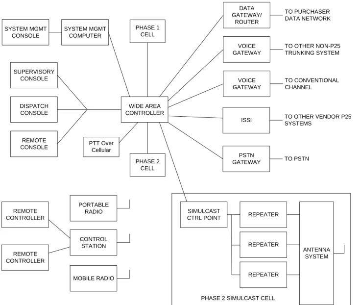
Figure 2-1 is a system context diagram of the Project 25 [A1]Phase 2[A2] trunked radio system,
showing the relationships of the system components.
The backbone of the system shall consist of one repeater site connected to a wide area controller, or switch, to provide reliable wide area voice and data communications to and from mobile and portable units throughout the desired area of coverage. To provide best value to Conway, Bidder shall maximize the use of commercial, off-the-shelf (COTS) Internet Protocol (IP) networking technologies for interconnectivity of network elements.
The network communications architecture shall provide the radio user transparent radio communications across the entire area of coverage.
The proposed system shall permit PTT over a cellular network to directly connect with PROJECT 25 trunk groups using standard PROJECT 25 codes.
The proposed Project 25 Phase 2 trunked radio system shall permit the radio user to roam across the entire area of coverage without requiring manual switching or changing of site information.
Dispatch consoles based upon the latest dispatch console and digital switching technology shall be utilized at the dispatch center sites. LED-based dispatch consoles shall provide the dispatcher with all the features and capabilities of a large, traditional, panel-mounted console in a compact unit. To provide the best value and flexibility to Conway, Bidder shall maximize the use of commercial, off-the-shelf (COTS) Internet Protocol (IP) networking technologies for dispatch console interconnectivity. Bidder shall indicate what types of workflow management are available on their dispatching system.
The PROJECT 25 Phase 2 trunked radio system shall provide automatic interoperability with existing trunked or conventional radio systems from the same or different manufacturers. Interoperability with other PROJECT 25 systems shall be supported through a PROJECT 25 ISSI 8000 (Inter Sub System Interface).
The location of the new PROJECT 25 system(s) shall comply with Motorola’s R56 Grounding Standard. If the City chooses to remain at the current RF site the Bidder will do a study to assure that the current site meets or exceeds Motorola’s R56 Grounding Standard.
WIDE AREA CONTROLLER MOBILE RADIO REMOTE CONSOLE DISPATCH CONSOLE SUPERVISORY CONSOLE SYSTEM MGMT CONSOLE SYSTEM MGMT COMPUTER PSTN GATEWAY VOICE GATEWAY VOICE GATEWAY DATA GATEWAY/ ROUTER PORTABLE RADIO CONTROL STATION REPEATER SIMULCAST CTRL POINT REPEATER REPEATER
PHASE 2 SIMULCAST CELL
TO PURCHASER DATA NETWORK TO OTHER NON-P25 TRUNKING SYSTEM TO CONVENTIONAL CHANNEL TO PSTN ANTENNA SYSTEM
ISSI TO OTHER VENDOR P25
SYSTEMS REMOTE CONTROLLER REMOTE CONTROLLER PHASE 1 CELL PHASE 2 CELL PTT Over Cellular
Page | 8
2.2 Phase 2 System Architecture
2.2.1 System Block Diagram
Bidder shall provide a complete high-level block diagram for the entire proposed system showing the site, wide area controller(s), dispatch consoles, and any other major system components (such as system administration and management computer(s), etc.).
2.2.2 Dispatch Center Locations
Conway desires to purchase 12 dispatch consoles to be located in the Conway Emergency Operations Center, 2300 Hogan Lane Conway, AR 72034 (Dispatch Center). Bidder shall provide a block diagram for the equipment at each dispatch center location, showing all major components and the quantity and type of communication circuits required to connect the dispatch center equipment to the wide area controller. Bidder shall provide a list of all power and air conditioning requirements for the dispatch center equipment.
University of Central Arkansas desires to purchase three consoles to be located in the dispatch center, located at 6 WJ Sowder Drive, Conway, AR 72035. Bidder shall provide a block diagram for the equipment at each dispatch center location, showing all major components and the quantity and type of communication circuits required to connect the dispatch center equipment to the wide area controller. Bidder shall provide a list of all power and air conditioning requirements for the dispatch center equipment.
2.2.3 Wide Area Controller Location
The primary wide area controller will be located at the Conway Emergency Operations Center, 2300 Hogan Lane Conway, AR 72034. The backup / WAC controller will be located at an alternate site determine by the Owner. Bidder may recommend the location of the backup wide area controller. Bidder shall provide a block diagram and floor plan for each wide area controller location, showing all major components and the quantity and type of communication circuits required to connect the wide area controller to remote consoles. Bidder shall provide a list of all power and air conditioning requirements for the wide area controller equipment.
2.3 Radio Coverage Requirements
Bidder will be responsible for demonstrating mobile and portable radio coverage performance in accordance with the test plan defined later in these specifications.
2.3.1 Coverage Predictions
Radio system coverage shall be predicted through use of a radio wave propagation model that has been developed on the basis of theoretical and empirical data, which will take into account terrain irregularity, foliage, urban clutter, noise and long and short term signal variations. The model used for the purposes of the coverage prediction shall be identified, and the rationale for system losses (e.g., power, gain, and loss information used in the model for each site) shall be described in the Bidder’s proposal.
Page | 9
2.3.2 Voice Quality
Coverage is defined as the minimum signal required to provide Delivered Audio Quality 3.4 (DAQ 3.4) voice quality, defined as “Speech understandable with repetition only rarely required”, as defined by TSB-88. Bidder shall relate this voice quality to a signal level or BER (Basic Encoding Rules) for acceptance testing purposes.
2.3.3 Mobile Coverage Requirement
Mobile voice coverage shall be provided with 95% or greater reliability. Bidder shall indicate what percentage of Conway (as defined by its political boundary) is predicted to have 95% or greater reliable coverage at DAQ 3.4 for a mobile. The Bidder’s percentage value will become the guarantee for pass/fail criteria for coverage acceptance testing. The boundary of the mobile service area shall be clearly indicated on the Bidder’s coverage maps provided with their proposal. Bidder shall provide all parameters and assumptions used to generate the coverage maps. Bidder shall provide detailed RF propagation coverage prediction analysis for both talk-out and talk-back for mobiles.
2.3.4 Portable Outdoors Coverage Requirement
Portable outdoor voice coverage shall be provided with 95% or greater reliability. Bidder shall indicate what percentage of Conway (as defined by its political boundary) is predicted to have 95% or greater reliable coverage at DAQ 3.4 for a portable. The Bidder’s percentage value will become the guarantee for pass/fail criteria for coverage acceptance testing. Bidder must assume that the user is outdoors and is wearing the portable (with antenna) on his hip and with a speaker microphone (no antenna) at shoulder height. The boundary of the portable service area shall be clearly indicated on the Bidder’s coverage maps provided with their proposal. Bidder shall provide all parameters and assumptions used to generate the coverage maps. Bidder shall provide detailed RF propagation coverage prediction analysis for both talk-out and talk-back for portables outdoors. Bidder shall provide a statement of talk-out to talk-back system balance.
2.3.5 Radio Frequencies
Conway has seven 800 MHz band frequencies allotted. The Bidder shall provide technical assistance to Conway in applying for three additional 800 MHz band frequencies. If no 800 MHz frequency licenses are available, the Bidder shall provide technical assistance to Conway in applying for three additional 700 MHz band frequencies. Conway shall be responsible for maintaining frequency licenses.
Bidder must indicate whether the default setting for talk groups on the system is message or transmission trunking mode; transmission trunking is preferred. Based on the default setting, Bidder must submit a traffic loading analysis that predicts the total number of active units that can be supported during the busy hour using the following profile.
Per User Number of messages per hour: 1
Number of PTT’s during a message: 6
Length of PTT spurt: 3.2 sec
Page | 10 Bidder’s system design must satisfy all requirements outlined by the regional plan and the FCC, regarding conformance to transmitter output power limitations. Bidder must include data in the proposal to demonstrate compliance, such as 40 dB contours[A3].
2.3.6 Tower Top Amplifiers
It is desirable that receiver tower top amplifiers be used to compensate for coaxial cable loss in order to provide the level of portable talk-back coverage specified. Bidders shall include tower top amplifiers.
2.4 System Functional Requirements
The basic operational mode of the system will be Project 25 Phase 2 trunked per TIA/EIA 102 standards, with the field units monitoring an assigned 9600 bit per second control channel. Most of the communications will use this mode with communications taking place over trunked repeater sites located throughout the served area. The mobile and portable radios will also enable users to manually select communication modes such as the use of conventional channels or talk-around mode when out of range of the repeater site.
2.4.1 Wide Area Communications
The system shall provide the ability to place and receive calls to and from any point in the network covered by the Project 25 trunked radio sites.
Bidders must include connectivity between the RF sites and the Dispatch Center. All sites shall be linked to the wide area radio network by means of microwave, fiber optic cable, or a combination thereof.
To provide best value to Conway, Bidder shall maximize the use of commercial, off-the-shelf (COTS) Internet Protocol (IP) networking technologies for interconnectivity of network elements. Bidder must indicate the amount of bandwidth required to support its proposed system design.
2.4.2 General Features 2.4.2.1 Voice and Control
Conway desires to utilize standards-based protocols for the life of the radio system. The system shall provide a minimum of two voice calls per 12.5 kHz of radio channel spectrum. Non-standard, proprietary TDMA (Time Division Multiple Access) solutions will not be accepted. The system must comply with the Project 25 Phase 2 standards, as described by the following published documents:
TIA-102.BBAA, Two-Slot TDMA Overview
TIA-102.BABA-1, Project 25 Half-Rate Coder Annex
TIA-102.BBAB, Project 25 Phase 2 Two-Slot Time Division Multiple Access Physical Layer Protocol Specification
TIA-102.BBAC, Project 25 Phase 2 Two-Slot TDMA Media Access Control Layer Description
TIA-102.CCAA, Two-Slot Time Division Multiple Access Transceiver Measurement Methods
Page | 11 TIA-102.CCAB, Two-Slot Time Division Multiple Access CAI Performance Recommendations
TIA-102.BCAD, Project 25 Trunked Radio System Two-Slot Time Division Multiple Access Voice Services Common Air Interface Conformance Specification
TIA-102.BCAE, Phase 2 Two-Slot Time Division Multiple Access Trunked Voice Services Message and Procedures Conformance Specification
TIA-102.CBBB, Two-Slot TDMA Messages and Procedures Conformance
TIA-102.CABC-B-1, Interoperability Testing for Voice Operation in Trunked Systems Addendum – TDMA Mode
TIA-102.AABC-C-1, Additions to the Phase 1 Trunking Standards for Phase 2 TDMA TIA-102.AAAD-A, Additions to the Phase 1 Encryption Standards for Phase 2, Encryption Protocol Addendum for Half Rate Coder
Proprietary encryption protocols are not acceptable.
The system must be able to support a mix of legacy Phase 1-only and Phase 2 radios on the Phase 2 system, and to allow for interoperability with neighboring Project 25 Phase 1 systems. The Phase 2 system shall allow legacy Phase 1-only radios to register and affiliate on interoperability groups. In addition, the registration of a Phase 1 radio on any PROJECT 25 site shall not reduce the Grade of Service (GOS) on Phase 2 sites that do not have Phase 1 radios registered on the same group.
2.4.2.2 Radio Disable
The purpose of this feature is to prevent a lost or stolen radio from being used to transmit and receive on the system.
The system shall have the ability to selectively enable or disable an individual radio from the system management computer.
Bidder shall indicate to what extent the proposed system is capable of preventing a stolen radio from accessing the system.
2.4.2.3 Caller Identification
The radio ID shall be included in each transmission. The system shall display this ID on its associated group module in the console at the dispatch center.
Suitably equipped mobile and portable radios shall be able to display the calling unit ID for both individual and group calls.
Each mobile radio, portable radio, control station, and dispatch console shall be capable of displaying an alphanumeric alias corresponding to the unit ID, if available from the transmitting device.
2.4.2.4 System Access by Unauthorized Devices
The system shall prevent access by unauthorized devices. The Bidder shall indicate whether this is accomplished through unit and group validation at the repeater controller, or through a unit authorization/registration procedure, or both.
Page | 12
2.4.2.5 Over-The-Air Provisioning
The system shall provide the ability to provision radio parameters to the mobile and portable radios over the air (without the need to physically connect the radio programmer to the radio). Provisioning shall include the supply of system information such as available radio channels, and user specific information such as talk group lists, scan priorities and user privileges.
2.4.2.6 Encryption and OTAR
Encryption on the system shall be PROJECT 25 standards-based; proprietary encryption protocols are not allowed.
The system shall support over-the-air-rekeying (OTAR) of mobile and portable radios using Project 25 OTAR. The system shall have the ability to schedule OTAR dynamically based on customer needs.
2.4.2.7 Radio to Radio Interoperability
Conway is also interested in purchasing full spectrum radios that operate on VHF, UHF, and 700/800 MHz frequency bands. The radios must operate in both analog conventional mode as well as PROJECT 25 Digital Trunked mode to facilitate cut-over from Conway’s current systems to the new PROJECT 25 radio system. Bidder shall provide optional prices for full spectrum portables and mobiles. Bidder must provide a live demonstration of the radio’s ability to scan between frequency bands and protocols.
2.4.3 Project 25 Trunked Features
2.4.3.1 Basic Project 25 Trunked Operation
The system shall support voice group operation, where a voice group consists of a number of operational users distributed through the radio network.
The radio user manually selects the voice group he wishes to communicate with, and then presses PTT on the radio. If resources are available the system shall respond by establishing a voice call to the selected group. Once the group call has been established, voice from the source radio is transmitted to all members of the group, which may involve multiple repeater sites. The system shall track voice group members as they roam through the network and ensure that each multi-site call is routed to all available repeater sites containing members of that voice group.
The system shall support Project 25-defined “announcement group calls” (allowing a dispatcher or authorized user to communicate to a number of individual groups) and “all calls” (allowing a dispatcher or authorized user to communicate to all users on the network.
2.4.3.2 Call Queuing
If resources are not immediately available for a call originating from the network side, the system shall queue the channel request to the base station until the radio channel is available.
2.4.3.3 Voice Group Priority
The base station shall queue calls originating from the network side based on voice group priority, with a minimum of eight priority levels. Calls will be positioned in the queue based on priority, with calls of highest priority (such as emergency calls) being serviced first. Calls of equal priority shall be processed on a first in, first out basis.
Page | 13
2.4.3.4 Group Busy Lockout
This feature prevents other voice group members from interrupting a user who is actively transmitting on a voice group.
If a member of a currently active voice group presses PTT to initiate a call on the same voice group, the system shall refuse to repeat the call. This is independent of the “Busy Channel Lockout” capability of the subscriber unit.
Exceptions to group busy lockout include network originated emergency calls, dispatcher override, and supervisor override.
2.4.3.5 Dispatcher Override
This feature ensures that calls originating from a dispatch console cannot be blocked by normal members of the same voice group.
The system shall permit a call originating from a dispatch console to interrupt a call by a normal member of the same voice group, overriding the call so that other members of the voice group only hear the dispatcher. The exception is the transmitting mobile, which may not hear the dispatcher until after he releases the PTT button.
2.4.3.6 Individual Call
The system shall support individual call mode, where a suitably equipped radio or console user can establish a private call to any other radio user in the network.
In individual call mode the group membership is limited to the source and destination radios and the call will not be overheard by other mobile or portable units.
Bidder shall indicate how an individual call is established in the proposed system.
2.4.3.7 Confirmed Call
Confirmed call is an optional feature where a voice group call is not enabled until most or all of the required system resources are available.
Bidder shall indicate the extent to which confirmed call is supported.
2.4.3.8 Priority Scan
The system shall provide individual radios with the capability of scanning multiple voice groups.
Bidder shall indicate the maximum number of voice groups on the scan list, and how the scan sequence is resolved if several voice groups are active at the same time.
2.4.3.9 Talkback Scan
The system shall provide individual radios with the capability of talking back on a scanned talk group.
2.4.3.10 Scan Group Lockout
The system shall provide the user with the ability to temporarily disable scanning on selected voice groups.
Page | 14
2.4.3.11 Emergency Alert and Emergency Call
The system shall support emergency notification in the mobile and portable radios.
When the emergency button is pressed on a mobile or portable radio, the radio shall immediately transmit an emergency alert message to the central dispatch location. The emergency alert message should include, at a minimum the radio ID talk group of the originating unit and the units location
Upon receipt of an emergency alert message the system shall immediately establish an emergency voice call. All emergency calls shall have the highest priority in the system.
2.4.3.12 Late Call Entry
The system shall permit a user who has just re-entered radio coverage or was engaged in another call to late enter into a call in progress.
2.4.3.13 Anti-Cloning of Radios
Bidder shall describe ability for Conway to prevent unauthorized users from cloning a radio’s personality to load into another radio.
2.4.4 Phase 2 Interoperability with Legacy Systems 2.4.4.1 Project 25 Conventional Systems
The Phase 2 system shall provide automatic interoperability with existing Project 25 conventional radio systems from the same or different manufacturers.
Automatic is defined as taking place without operator (user or dispatcher) intervention. It is acceptable for an operator to be required to set up the initial connection. However, all subsequent inter-system communications should occur without human intervention.
Interoperability is defined as the capability to connect to Project 25 conventional voice groups on the Phase 2 radio system through the wide area controller.
It is preferred that a user registered on a PROJECT 25 Conventional channel would use the same talk group as a user on a PROJECT 25 Trunked site. If this feature is not available, then Bidder shall describe how the proposed PROJECT 25 Phase 2 Trunked system will interface with a PROJECT 25 Conventional system, including the steps the users have to take to initiate an inter-system group call.
2.4.4.2 Project 25 Legacy Phase 1 Trunked Systems
The system shall provide automatic interoperability with existing Project 25 Phase 1 trunked radio systems from the same or different manufacturers. Interoperability is defined as the capability to connect or patch Project 25 trunked voice groups on the Phase 2 radio system through the wide area controller with Project 25 trunked voice groups on an existing radio system. This interoperability may be established using network-level connectivity compliant with the PROJECT 25 Inter-Subsystem-Interface 8000 (ISSI 8000).
Page | 15
2.4.4.3 Conventional FM Systems
The system shall provide automatic interoperability with existing conventional FM radio channels, where a voice group on the new system is connected through the wide area controller to a conventional FM radio channel, or alternatively to a CTCSS defined voice group on a conventional FM radio channel. Automatic is defined as taking place without operator (user or dispatcher) intervention. It is acceptable for an operator to be required to set up the initial connection. However, all subsequent inter-system communications should occur without human intervention.
The existing conventional FM radio systems to be interfaced may operate in the VHF, UHF, 700 MHz or 800 MHz frequency bands. The conventional FM station interface shall accommodate any one or all of these. Interoperability is not required at the air interface. The system shall support statically defined interfaces between CTCSS talk groups on conventional channels and talk groups on the new system, where once the interface is configured it is not changed.
The system shall support dynamically defined dispatch console patch style interfaces between conventional channels and talk groups on the Phase 2 system, where the interface can be configured by the dispatcher.
2.4.4.4 City of Conway Interoperability
Conway requires interoperability with the following agencies:
Agency System
AWIN P 25 Motorola
Faulkner County Volunteer Fire Department VHF
For agencies with proprietary trunking systems, Bidder must propose interoperability through the use of dedicated control stations and interoperability gateways such that a Conway user may simply select an interoperability talk group when communication with a neighboring agency is desired. For agencies with PROJECT 25 trunking systems, Bidder must propose interoperability through the use of a PROJECT 25 Inter Subsystem Interface 8000 (ISSI 8000). In addition, the system shall control the new trunked radio system and all current VHF and UHF channels. Hard patches, not controlled by the console operator, shall be provided between existing conventional radio channels and selected talk groups during the changeover to the new trunked radio system.
Page | 16
2.4.4.5 Interoperability Block Diagram
Bidder shall provide a block diagram of the network-level interoperability subsystem, including how it ties into the PROJECT 25 Phase 2 trunked radio system. The block diagram shall show all major components and the quantity and type of communication circuits required, including bandwidth requirements, to tie the legacy radio systems into the PROJECT 25 trunked radio network.
2.4.5 System Reliability and Fault Tolerance
System reliability and fault tolerance shall be major objectives in the design of the system. The system shall be designed to operate reliably, so that if a problem develops it will not affect the basic trunking operation and will not propagate to another part of the system.
Bidder shall describe in detail all measures taken to ensure reliable operation of the system including, as a minimum, the Project 25 trunked repeaters, channel controllers, and wide area controllers.
2.4.5.1 Wide Area
The system shall be designed such that there are no situations where a single failure in Bidder supplied equipment will disable wide area operation.
No single point failure within the wide area controller shall prevent the system from normal operation.
Bidders are required to provide hot standby redundancy for the wide area controller. The hot standby equipment shall be placed at a location several miles from the Dispatch Center for geographical redundancy. Upon a failure of the primary network controller, the redundant controller shall automatically take over with no user intervention required.
If the Bidder’s solution consists of a single site and wide area multisite, should one or more site elements or site links fail, the rest of the system shall continue wide area communication, and the isolated sites shall continue standalone Project 25 trunked operation. The system shall be reliable such that a failed link to any site will not affect the rest of the wide area communications.
2.4.5.2 PROJECT 25 Trunked Site
The PROJECT 25 trunked repeater site shall not be dependent upon the wide area controller for operation. If a Phase 2 trunked site loses its communication to the wide area controller it shall continue to operate on a single site basis. Wide area communications will continue except for the site that lost its link.
Should a radio channel fail at a multi-channel site, there shall be no functional impact on the operation of the system other than reduced site capacity.
2.4.5.3 System Management Computer
If the proposed architecture consists of a single system management computer, a redundant configuration shall be available. It should be possible to locate the redundant computer at a site several miles from the primary system management computer.
Page | 17
2.4.5.4 Dispatch Console and Console Switch
In case of failure of one console position, no other console position shall fail as a result of that failed console.
If the proposed system requires a separate console switch, the console switch shall have redundant operation such that no single failure within the console switch shall prevent the unit from normal operation.
2.4.5.5 Mobile and Portable Behavior
If an entire site fails, the mobiles and portables using that site shall automatically, as coverage allows, roam to adjacent sites.
2.4.5.6 Failure Mode Analysis
Bidder shall indicate the impact on system operation of each of the following system element failures, how the system responds, and what features, if any, are lost:
Working Channel Failure
Control Channel Failure
Site Controller Failure
Dispatch Console Failure
Wide Area Controller Failure
System Management Computer Failure
Backhaul Link Failure
Power failure
2.4.6 Network Security and Information Assurance
While IP-based radio solutions provide benefits such as a common backbone and infrastructure, commercially available standard products, common support and maintenance, and flexibility for newer technologies, the trade-off is to ensure that cybersecurity is established and maintained. The City of Conway must have a communication network that provides confidence and trust that their system is maintaining their confidentiality, the integrity of their data, and the availability of their system. The cybersecurity posture shall meet City of Conway organizational requirements throughout the lifecycle of the system. In addition to required cybersecurity features (i.e. Active Directory, bulk encryption), optional cybersecurity features will be integrated in the systems design per City of Conway discretion to achieve appropriate baseline security posture. The VIDA Network will be secured using a defense-in-depth strategy. This strategy will combine a range of cybersecurity methodologies that incorporates not only technology, but operations and personnel. This strategy provides resilient LMR operations, while minimizing failure and intrusions, and mitigating the risk of any one defense being compromised or circumvented. Therefore, Bidders must explain their cybersecurity methodology as it pertains to:
National Fire Protection Association (NFPA) 1221 Standard for the Installation, Maintenance, and Use of Emergency Services Communications Systems, which has a new chapter on data security that is out for comment.
Page | 18 Federal Bureau of Investigation’s (FBI) Criminal Justice Information Services (CJIS) Security Policy that includes all those that support the FBI & Do. [CJISD-ITS-DOC-08140-5.0] NIST Recommendations on Cyber/Computer Security (Special Publications 800 Series) A Layered Defense – Not depending on a single technology or methodology to provide trust Defense in Depth - An approach whereby security is addressed with Personnel, Operations, and Technology
Industry Best Practices – As can be demonstrated by Consensus Audit Guidelines, Federal Desktop Guidelines, etc.
COTS Based Solutions - Designed and implemented to industry-standard security practices, as far as it is practical
At a minimum the following optional cybersecurity features should be considered per industry best practices:
Perimeter Firewalls
Network Intrusion
Detection and Prevention
Link Encryption
Patch Management
Host-based Security
Network Infrastructure Management
Network Intrusion Management and Monitoring
Centralized Log Management
Continuity of Operations and Disaster Recovery
Security Information and Event Management
2.4.6.1 Successful Implementation of Secure Wireless System
Bidder must provide at least 5 references that demonstrate experience in the integration, design and construction of critical communications systems that require a very high level of survivability and reliability. Further, Bidders should identify and define their capabilities, such as where they have expertise and what their track record with such programs is. Bidder must indicate whether they have the personnel on staff to implement and carry on follow-up support or if this support is out-sourced.
Page | 19
2.4.6.2 Controlling System Access
The main goal of any information system is to restrict access to those who are authorized to and have a need to know, including the ability to audit the information system to ensure that the policies and regulations are being implemented appropriately and to provide accountability for the actions of those with the responsibility of using and administering the system.
2.4.6.2.1 Authentication, Authorization and Accountability
Access control requirements should seek to ensure that the system maintains not only confidentiality of information but also ensures the integrity of that information with role-based access control. Access control should involve the implementation of least privileges, authentication, authorization, and accountability; a vendor should meet the following Access
Control requirements:
Centralized Authentication, Authorization, and Accountability of Users, Role-based management of users and machines, Provide the capability to audit the information system to ensure that the policies and regulations are being implemented appropriately, and Provide accountability for the actions of those with the responsibility of using and administering the system.
Bidder must explain how their network accomplishes these goals.
2.4.6.2.2 Identity Assurance
A key component within Cyber Security and Access Control is the concept and methods of Identity Assurance that addresses minimizing business risk associated with identity impersonation and inappropriate account usage. Access in high-risk situations (e.g. Remote Access) should be performed with the use of two-factor (or strong) authentication by which the user must provide their account name, account password (something they know), and either a token ID (something they have) or biometric information (something they are).
Bidder must use their risk management framework to identify these high-risk areas requiring two-factor authentication and explain how their network accomplishes these goals.
2.4.6.3 Operational Security
Agencies need to integrate security into their operations. A wireless information system, integrated into the overall information system of an organization, needs to take some key aspects into consideration such as
Centralized Log Management,
Security Event and Information Monitoring, and
Business Continuity and Disaster Recovery.
2.4.6.3.1 Interoperability
To minimize duplication of administration, equipment, and time, it is becoming common to interconnect the LMR system with the enterprise network through a highly restricted firewall and/or intrusion prevention system (IPS). Bidder shall describe how their Authentication and
Page | 20 Authorization Server (AAS) integrates with Conway’s existing AAS to allow for the sharing of users identifications and passwords, preferably one-way.
To support auditing, detection, and accountability practices, Bidder shall include how their technology will respond to the needs and be a part of a centralized log management system along with having secure long-term data retention capable of NAS, SAN and WORM storage connectivity. A log management solution should be capable of monitoring and recording system and event logs from a large number of the devices on the network, including (but not limited to): Operating System Event Logs, Application Logs, and
Network Device Logs.
Bidder shall ensure that all security appliances and systems are capable of integrating with the existing enterprise SEIM.
2.4.6.3.2 Continuity and Disaster Recovery
During critical operations, the system shall be able to quickly recover devices to bring the users and the system functionality back to full operational status. Bidder shall describe whether their backup solution is easily administered and maintained, supports all operating systems, is capable of bare metal restore, and is cost effective across the entire life cycle of the system. An enterprise backup solution should also have the capability of creating offline backups that can be stored off site.
2.4.6.4 Computer Security
Computer systems have become the primary resource for not only storing information but also the primary workhorse for users to perform their jobs, and therefore has become a primary objective for intruders for either data gathering or destruction. This makes a computer system the end point for security that layers need to be built around to minimize the risk associated with the information they contain or with the trusted capability placed at their disposal.
2.4.6.4.1 Patch Management
A common approach to gaining access to unauthorized systems is to leverage a known vulnerability within a software system, which is why it becomes important to ensure that the system is properly maintained throughout the life cycle of the system with up-to-date software versions and patches that close vulnerabilities and bugs to prevent them from being exploited. Bidder shall describe how they can accommodate continuous patching of the LMR system that addresses all software provided with the system including operating systems, third-party applications (e.g. PDF readers, Antivirus, Web Browsers, etc.), and vendor applications that have been thoroughly vetted through a verification and validation lab.
The patch management solution should be capable of providing the following minimum functionality:
Centralized role-based Administration,
Integration with Authentication and Authorization Server,
Page | 21
Air-gap patch capability that requires the updating of the Patch Management Server with Mobile Media (e.g. DVD or Thumb Drive) without connectivity to the internet being required,
Standard capabilities available from commercially available Patch Management Systems, and
The ability to express-test critical vulnerabilities out-of-cycle when the need arise to keep critical systems going.
Bidders shall include patch management costs for the first year as part of the base bid and provide annual costs as an option with any multiple year discounts detailed as well.
2.4.6.4.2 Security Policies
The LMR system provided by the Bidder shall include the setting and periodic update of appropriate security policies for the operating systems set according to each devices’ capabilities to the maximum possible to allow reliable operation, maintenance, and administration. These security policies shall be configured to provide the least privilege necessary based upon the authorized role of the user from the authentication and authorization server (e.g. Console Dispatchers do not need USB mobile media). Bidder shall describe how their network accomplishes these goals.
2.4.6.4.3 Host-based Security
Host-based Security is applying a suite of software or software functionality within a single application that protects the host computer from malicious behavior. Antivirus is an absolute minimum to protect workstations and servers from malicious code, as most individuals accept for even their home computers, but it does not provide a complete solution for all the vectors that malicious behavior can occur from zero-day viruses which are not found by antivirus software, intentional attacks through bugs, or even accidental user actions. A comprehensive host solution is necessary for ensuring proper protection from known attack vectors and unallowable behaviors to anomaly detection for incident handling and chain of events. Therefore, the Bidder shall provide antivirus for all systems capable of supporting such an application, and will provide host-based security software (HBSS) for all Servers and high-risk machines, and a centralized server responsible for management, updating, and monitoring of the host security.
2.4.6.5 Network Security
Bidder shall provide multiple network security capabilities to address the risk associated with routed networks including Access Control Lists on Routers, Firewalls, Network Intrusion Detection, and Link Encryption.
2.4.6.5.1 Firewalls
Bidder shall include firewall protection to deliver strong network- and application-layer security, user-based access control, worm mitigation, malware protection, and improved employee productivity. Bidder shall describe how their network accomplishes these goals.
Page | 22
2.4.6.5.2 Network Intrusion Detection & Prevention
Bidder shall include Network Intrusion and Detection Systems (NIDS) to allow for a combination of vulnerability- and anomaly-based inspection methods to analyze network traffic and prevent threats from damaging Conway’s network by alerting system administrators or preventing suspicious behavior. The Bidder shall use their risk management framework to determine and explain the placement of Network Intrusion and Detection Systems. The vendor shall also provide a NIDS management console that is capable of correlating attacks with real-time network and user intelligence and centrally manages network security and operational functions, including event monitoring, incident prioritization, forensic analysis, alerting, and reporting.
2.4.6.5.3 Link Encryption
Bidder shall provide link encryption for all backhaul connections or connections that traverse public or insecure zones. Bidder shall describe how their network accomplishes this goal.
2.5 System Performance Requirements 2.5.1 Voice
The system shall support a fleet of at least 5000 registered voice users. The system shall support a minimum of 2000 voice groups.
2.5.2 Expansion Capability
The system shall be capable of expansion to support a minimum of 50 dispatch consoles.
2.5.3 Failover
A hot standby wide area controller (Site B) shall take full control within 60 seconds after sensing that the primary (Site A) unit has failed. Any loss of voice communications shall be limited to the interval from the failure of the primary unit to the time the standby unit takes full control.
2.5.4 Interoperability
The system shall support a minimum of 20 statically defined interfaces between CTCSS talk groups on conventional channels and talk groups on the new system.
2.6 Equipment Requirements 2.6.1 Repeater Sites
Equipment provided at each site shall consist of repeaters and all other associated hardware and software for a digital Project 25 trunked system.
2.6.1.1 Project 25 Trunked Repeater Stations
The Project 25 trunked repeater station is considered to include the station channel controller. All repeaters shall be capable of being configured to provide Project 25 trunked voice and data transmission to user radios. All repeaters shall be capable of being configured as either a
Page | 23 Project 25 control channel or working channel, and any working channel repeater shall be capable of automatically assuming the role of the control channel in the case of a failure of the control channel repeater.
Repeaters shall provide automatic call sign identification that meets the FCC requirements for identifying Project 25 trunked repeater sites.
The system shall provide the ability to reconfigure individual repeaters through the network backhaul interface. The Bidder shall indicate the extent to which repeater parameters can be configured remotely, and whether this programming is restricted to repeater parameters or also includes repeater software.
2.6.1.1.1 Control and Alarms
The Project 25 trunked repeater station shall be controlled and managed through the system management computer, which shall be capable of remotely controlling the following functions:
Taking a repeater off-line
Retrieving and setting repeater operating parameters
2.6.1.1.2 Physical and Environmental
The Project 25 trunked repeater stations, including repeater and station channel controller, shall be housed in standard 19 inch EIA rack mount free standing cabinets, with three stations (or more) per cabinet to conserve space.
All hardware and software necessary for the stations to meet the system requirements shall be provided.
The equipment shall operate over a temperature range of –30 degrees to +60 degrees Celsius. All temperature sensitive specifications shall be referred to +25 degrees Celsius.
All components within the repeater shall be of solid state design.
The repeaters shall meet or exceed all applicable FCC requirements and fully comply with EIA standards as they apply to measurement of specifications.
2.6.1.2 Antenna System
Transmitter combiners and receiver multicouplers shall be installed in cabinets with space available to expand to the number of channels specified in Section 2 System Architecture.
2.6.1.2.1 Transmitter Combiner
The transmitter combiner shall be the expandable type supplied with the number of ports specified.
2.6.1.2.2 Receiver Multicoupler
The receiver multicoupler shall be the expandable type supplied with the number of ports specified with all unused ports terminated with 50 ohms. A bandpass cavity filter shall be supplied with the multicoupler to reject out-of-band RF signals.
Page | 24
2.6.1.3 Site Alarms
The system shall be capable of detecting the failure of all major equipment items at the repeater site, including at a minimum:
repeater operation
channel controller operation
status of leased landline or microwave link
status of antenna system (VSWR)
status of tower top amplifier (if present)
failure of AC power (if there is a backup system)
failure of DC power (if there is a backup system)
site or rack intrusion alarm
2.6.1.4 Network Equipment
If network equipment is included at the site for IP connectivity, Bidder shall use commercial-off-the-shelf components. Bidder shall identify whether the equipment requires hardware or software modification for use in their radio system.
2.6.2 Wide Area Controller
The wide area controller shall provide intelligent interconnection of the Project 25 trunked radio sites and dispatch consoles to form a fully integrated radio system supporting wide area voice communications.
The wide area controller shall track each Project 25 trunked radio and its affiliated talk group as it roams throughout the coverage area of the multisite network. The wide area controller shall route calls to individuals or groups at the appropriate sites. A mobile or portable radio shall be de-registered from a site when it logs onto a new site, or after a programmable period of inactivity.
The wide area controller shall be capable of interfacing to other wide area controllers.
The wide area controller shall also interface with, or be expandable to accommodate multiple Project 25 conventional radio sites, multiple conventional radio channels, multiple dispatch consoles, centralized telephone interconnect system, voice logging recorder, and system management computer.
Complete control over the wide area controller shall be provided to authorize persons through the system management computer.
The wide area controller shall be powered from 115 VAC 60 Hz. Bidder shall specify current requirements.
The wide area controller shall include a hot standby backup controller, which is geographically separated.
Page | 25
2.6.3 System Management
The system management device shall be a UNIX or Windows 7 based computer with a client/server architecture and single-point database for all system management functions. The system shall include at least one system management console which provides system management of the entire system. Control of the management console will include a rack mounted KVM over IP the city prefers Raritan Dominion KX II.
The system shall be capable of supporting multiple system management operator consoles operating concurrently at different locations within the wide area network.
The system management computer and consoles shall be powered from 115 VAC 60 Hz. Bidder shall specify current requirements.
2.6.3.1 Polling and Alarms
The system management computer shall support polling and alarms.
System devices which detect that they have changed status or are operating below specification shall automatically transmit an alarm to the system management computer. In some cases device failure will prevent the transmission of an alarm, these situations will be detected through polling.
The system management computer shall automatically and routinely poll system devices to determine status. The polling interval should be automatically adjusted by the system management computer to avoid unnecessary polling, for example if the device has just reported a change in status through the alarm mechanism.
At minimum, detection of the following alarms must be included: RF Power Failure
Excessive VSWR Shelter Door Alarms Cabinet Door Alarms Line Power Failure UPS Power Failure Generator Failure Smoke Detection Humidity Detection HVAC Failure Low Generator Fuel Low Battery
Page | 26
2.6.3.2 Network Topology Map
The system management computer shall provide a hierarchical network topology map, showing all managed devices using color coding to represent device status.
Through the network topology map it shall be possible for the operator to determine the current detailed status of a managed object, by double clicking on the object.
2.6.3.3 Fault Browser
The system management computer shall provide a scrollable, time sorted list of alarm messages sent by managed objects.
2.6.3.4 Audible Alert
It should be expected that due to the high reliability of the system, the system management computer console will be unattended most of the time with the operator working in the area on other tasks.
The system management computer shall provide a programmable audible alert to notify the operator of changes in the system status.
2.6.3.5 Data Base Partitioning and System Security
The system management function shall be capable of partitioning the database such that different managers (e.g. supervisor vs. non-supervisor) have control only over the units and groups for which they have been authorized.
The system management function shall have multiple levels of security access.
2.6.3.6 System Administration
The system management computer shall support establishing and updating repeater site parameters, and remotely enabling and disabling radios.
The system management computer shall support the registration of new voice users in the system and assigning voice group membership.
2.6.3.7 Statistics
The system management computer shall collect and save the following statistics for later analysis:
voice traffic volume by subscriber unit per hour voice traffic volume by repeater per hour
wide area controller voice traffic volume per hour
2.6.3.8 Call Activity Logging
The purpose of this feature is to determine the relative traffic loading and geographic distribution for each of the voice groups using the system. This can be used for billing different user groups, and in engineering the system for increased busy hour capacity.
The system management function shall maintain a record on hard disk of all voice call activity for a period of up to 45 days, with the capability to down load to tape or other storage media when desired.
Page | 27 The system management function shall be able to continue to log call activity when a report is being run, and when downloading to the supported storage media.
The following data should be stored as a minimum: Date, time, and duration of call
Type of call (group, unit-to-unit, emergency)
Unit initiating call and voice group number (group calls only) Unit initiating call and target unit number (unit-to-unit calls only) Repeaters and/or consoles participating in the call
Usage time for each repeater at a site
The number of minutes by site that all of the channels at the site are busy
2.6.3.9 Remote Diagnostics
The system management function shall permit the operator to run remote diagnostics on managed devices to isolate and trouble shoot faults.
2.6.4 Dispatch Consoles
The system shall support dispatch console operation over a district, region, and system wide basis.
The dispatch consoles are of three types: normal, supervisory, and remote consoles.
Console connectivity to the network controller shall use a direct IP interface, allowing consoles to located wherever IP network connectivity is present. Optional software features for the dispatch console shall be field programmable through changes in firmware or software. Adding or deleting modules and changing module names shall be software programmable.
2.6.4.1 Physical and Environmental
Dispatch console equipment shall be powered from 115 VAC at 60 Hz. Bidder shall specify required current levels.
The dispatch console shall not be affected by temporary power loss and shall be supplied with an uninterruptible power supply (UPS) that supports approximately ten minutes of backup operation in case of power failure.
2.6.4.2 Dispatch Console Equipment
The computer for the console shall have the following minimum hardware specifications: A LED 22” (minimum) touch screen monitor shall be offered with the console computer and audio system.
A dual headset jack shall be included.
A single footswitch with high durability shall be included to provide PTT for the headset. The footswitch shall be heavy-duty and non-skidding.
Page | 28
2.6.4.3 Supervisory Console
The supervisory console shall have the same features as a normal dispatch console, with the following additions:
The supervisory console shall be able to listen to any of a programmed individual entity radio calls. The supervisory console shall be able to display an emergency declared on an un-programmed talk group. The supervisory console shall be able to disable a non-supervisory console.
The supervisory console shall physically be the same as other consoles except that it has been programmed to have supervisory capabilities.
2.6.4.4 Dispatch Console Functionality
The console application shall run on the Windows-based operating system, Windows 7, Server 2008 R2, or later. The console shall be software driven to allow for access to future features and technologies.
The console shall be easy for a properly trained dispatcher to use. It shall enable the dispatcher to perform dispatch tasks efficiently and with minimal confusion due to screen clutter. The displays on the monitor shall have clearly distinguishable words so that there is no confusion over the operation function of a particular button. The process of maneuvering through functions on the screen shall be possible through the mouse or touch screen.
2.6.4.4.1 Screens
The console shall be able to support up to ten user-defined screen set-ups (appearances) to enable each dispatch shift to set its own screen appearance. These screen appearances shall be pre-configurable and selectable by the dispatcher.
The clock shall display in 12-hour format or 24-hour format.
The console shall have a dedicated display for system related messages. These messages shall include information regarding emergencies, console set-up, patch, and simulselect.
The console shall display in a dedicated panel the individual unit alias with whom the dispatcher is conversing.
The console shall display the console identification number.
The display and operation of the command buttons shall be independent of the display and operation of the page/modules. The console shall allow the flexibility of having operations commands display in combination with any screen. The screen and command button labels shall be displayed with distinguishable text.
2.6.4.4.2 Modules
The console shall support and display audio communications modules, where a module is a dispatcher defined space in a view screen that permits voice communications.
A module shall be programmable to support communication with one or more entities, which could include:
Page | 29 a trunking talk group
an individual call a conventional channel another console
status (inbound data messaging) paging (outbound data messaging)
auxiliary I/O (bi-directional data messaging)
The console shall support a minimum of 100 different modules. If a module is in use at one console, a busy indicator shall be displayed at the other consoles in the system.
For received calls, an alias (alpha-numeric representation of the radio terminal) shall be displayed in the appropriate module.
The console shall permit the operator to monitor call activity using up to four separate speakers, one with select audio and the others with unselect audio. The console shall permit the dispatcher to route any module to the speakers.
Each module shall have its own volume adjustment. The console shall be capable of muting individual modules or758 all unselected modules.
The console shall be able to display the call history of a particular module. The call history display shall place the most recent call at the top of a scrollable list of up to five entries. The console shall also be able to display a comprehensive call history for each module including up to 64 most recent calls.
2.6.4.4.3 Patches
The console shall support patches, which involves temporarily combining two or more modules. A patch merges the entities into a super group, such that each member hears every other member.
Each console shall be able to support up to five patches with up to 15 entities (groups and/or channels) each. All entities patched together shall be able to communicate with one another. The console shall support pre-configured patches.
2.6.4.4.4 Simulselect
The console shall support simulselect, which involves temporarily summing two or more modules at the console. Simulselect merges the entities for the benefit of the dispatcher, however does not create a super group. Only the dispatcher can hear all simulselect members. Each console shall be able to support up to four Simulselects with up to 15 entities each. The dispatcher shall be able to communicate with all entities contained in a single simulselect. The console shall support pre-configured simulselects in conjunction with the simulselect feature support within the Project 25 conventional/conventional system.
Page | 30
2.6.4.4.5 Other Consoles
The console shall be capable of muting the audio from other consoles.
For consoles connected to the same switch, two console operators shall be able to communicate with one another through an intercom feature. No RF channel shall be utilized during the inter-console communication.
2.6.4.4.6 Emergency
During emergencies, the console shall give both visual and audible alert. The module and page with the emergency shall be displayed in red. The module and the call history shall display the alias of the unit declaring the emergency. Further, the emergency shall be displayed in the system information panel, which shall be red.
If an emergency is declared when another emergency already exists:
Same group: If the original emergency has not been acknowledged, the console shall display a counter with the emergency message to indicate the number of emergencies for the same group. The declaring alias shall be displayed in the appropriate call history display.
Different group: The new emergency shall also be declared and shall exist with the original emergency. Both modules shall be red. The declaring alias shall be displayed in the appropriate call history display. The emergency message shall correspond to the most recently declared emergency.
The dispatcher shall be able to declare an emergency and clear an emergency at the console.
2.6.4.4.7 Telephone Patch
The console shall be able to interface to equipment to support a telephone patch. Audio shall be routed to a headset, if present. If no headset is used, the telephone audio shall be routed to the select speaker with all other audio routed to the unselect speaker. The console shall be able to display whether or not the console is involved in a phone conversation.
2.6.4.4.8 Conventional Channels
The console shall be able to control conventional channels and (in conjunction with a conventional base station that supports these functions) provide the following functions: Select the stations transmit/receive frequency pair from a pre-defined list.
Enable the base station to repeat radio-originated audio. Enable the base station to be controlled by remote controller. Enable scan of selected channels of a multi-channel base station.
Enable toggling between main conventional base stations and standby conventional base stations.
The console operator and the conventional channel shall be able to use a high fidelity PCM vocoder (i.e. ADPCM) that can carry complex paging plans (outbound calls) and preserve voice quality in marginal RF conditions on the analog channel on inbound calls to the console