Electric Fence Energizer
Installation and Operating Instructions
WARNING:
READ ALL INSTRUCTIONS BEFORE INSTALLATION.
SAVE THIS BOOKLET FOR FUTURE REFERENCE.
SOLAR ENERGIZER MAINTENANCE
• Check the energizer regularly to insure operation is normal.
• Clean the surface of the solar panel regularly. Use a soft, damp cloth. Do not use abrasive materials that could scratch the panel.
• Set the toggle switch in the “OFF” position when not using the energizer for more than 5 days. This prevents overcharging of the battery.
• DO NOT use any means for charging the internal battery except for the solar panel or a constant potential current limited 12VDC battery charger rated at 500 milliamps maximum.
• When storing the energizer, place the energizer in strong direct sunlight for 2 days every 3 months with the switch in the “CHARGE” position. Put switch back into the “OFF” position for storage.
WARNING: SAVE THESE INSTRUCTIONS
SAFETY INFORMATION
DANGER – DOUBLE INSULATED: when servicing, use only identi-cal replacement parts and by qualified service personnel only. Double insulated energizers include two systems for insulation.
CAUTION: To reduce the risk of electrical shock do not remove cover. Refer to service personnel.
Afin de reduire les risques d’electrocution, ne retirez pas le couvercle. Adressez vous au personnel de service.
WARNING: Do not connect simultaneously to a fence and any other device such as a cattle trainer or a poultry trainer. Otherwise, lightening striking your fence will be conducted to all other devices.
AVERTISSEMENT: ne pas raccorder siultanement a une cloture et a un
au-Warning: Read All Instructions
Attention: Lire Toutes Les Instructions Warning: Save These InstructionsGuardar estes instucoes
CAUTION
vegetation, buildings and roof overhangs will not block sunlight from the panel.
A. A fully charged battery will operate the energizer for up to 18 days in darkness before the energizer will stop. At this point, the battery is almost completely discharged.
B. A fully discharged battery will require 20-25 hours of recharging with the solar panel in strong sunlight before operating the energizer. On average, 6-8 days of charging in sunlight will restore a fully discharged battery. Recharge battery with the toggle switch in
the “CHARGE” position.
5. Upon completion of battery charging, the energizer is ready to be installed on the fence. Locate energizer so that solar panel is facing due south into the sun at its highest point at 12:00 noon. Select a location where solar panel will never be shaded from the sun. Locate the energizer out of reach of animals and children. Secure the energizer so that solar panel will not move away from the sun.
6. Connect fence and ground wire to labeled terminals and move toggle switch to “ON” position. Red light will flash when energizer is operating.
tre dispositif tel qu’un enclos de dressage du betail ou un poste de condi-tionnement de la volaille. Sinon, si la foudre frappe la cloture, le courant de la foudre sera transmis au dispositi.
To reduce the risk of electric shock, an ac line operated fence controller has a polarized plug (one blade is wider than the other). The plug will fit in a polarized outlet only one way. If the plug does not fit fully in the outlet, reverse the plug. If it still does not fit, contact a qualified electrician to install the proper outlet.
Afin de reduire les risques d’electrocution, un controleur de cloture alimente sur ligne ac est muni d’une prise polarisee (un lame est plus large que l’autre). Cette pris s’emboite dans une sortie polarisee que d’une maniere. Si la prise ne s’engage pas totalement dans la sortie, inversez la prise. Si elle ne s’engage toujours pas, contactez un electricien qualifie pour installer une sortie appro-priee. Ne changez la prise en aucune maniere.
This fence controller is not to be permanently mounted using conduit.
SUPPLEMENTAL INSTRUCTIONS FOR BATTERY POWERED ENERGIZERS
1. Use a Deep Cycle Rechargeable Battery rated at 60 amp hour or greater. Marine batteries are recommended.
2. Avoid placing battery directly under energizer so that corrosive gases will not damage the energizer. Locate the battery in a cool and dry area for best performance.
3. Place the battery away from sparks and in a well-ventilated area for safety. Check battery voltage and energizer performance regularly to ensure con-tinuous operation.
SUPPLEMENTAL INSTRUCTIONS FOR SOLAR CHARGED ENERGIZERS
1. Remove all labels from front of solar panel and clean panel with a damp cloth.
2. Make sure that the lead wire running from the solar panel is connected to the fence energizer.
3. Put toggle switch in the “CHARGE” position.
4. IMPORTANT: BEFORE INSTALLING ENERGIZER ON THE FENCE LINE, mount energizer upright in a location outdoors that will receive the maxi-mum available direct sunlight for a minimaxi-mum of 4 days. Face the energizer due south, into the sunlight. Energizer should be in a location where trees,
ADDITIONAL SAFETY GUIDELINES - PLEASE READ CAREFULLY:
1. CAUTION: RISK OF ELECTRIC SHOCK. Do not install where small children, the elderly or unhealthy persons may come in contact with the live portions of electric fencing. Use electric fence warning signs wherever humans may come in contact with the fence.
2. NEVER electrify barbed wire or loose fencing materials that risk entanglement of a human or animal. Exposure to continuous or multiple shocks is very dangerous.
3. STAY AWAY from the fence energizer and from the fence line just before and during lightning storms. In lightning prone areas, disconnect the energizer from the fence and from the power supply in advance of storms to prevent damage to the energizer.
4. FOLLOW all national, state and local regulations that may apply to instal-lation of electric fence in your area.
5. REFER TO AUTHORIZED REPAIR CENTER FOR SERVICE. There are no user serviceable parts. Never alter the design of the energizer. Doing so is hazardous and will void the warranty.
6. ALWAYS unplug the energizer before handling any part of the energizer. 7. NEVER put more than one energizer on a fence. Doing so is dangerous
because it may reduce time off between pulses, may damage the ener-gizer and will invalidate the warranty.
– 5 –
8. DO NOT run fence wire above ground near high voltage power lines. If too close, the electric fence may pick up dangerous levels of power from high voltage lines. Never cross under a high voltage line with electric fence. 9. ALWAYS maintain an adequate ground system securely attached to the
energizer.
10. DO NOT alter the polarity of the energizer plug on 110V operated energiz-ers. For battery operated fence energizers, connect the red battery clamp to the positive battery terminal and the black battery clamp to the negative battery terminal only.
11. NEVER charge a battery that is connected to a fence energizer. Always disconnect the battery from the energizer first.
12. WARNING! Electric fences are very effective psychological barriers when properly installed and when animals are trained to the fence. Electric fenc-es are NOT complete physical barriers. Erratic animal behavior cannot be predicted and occasional fence penetration can occur. Therefore, we as-sumes no liability for animal containment, injury or the consequences for the misuse of the equipment.
13. WARNING! Never touch the live fence with the head or mouth.
14. WARNING! Sparks may occur in electric fence systems. Therefore, during periods of high fire risk, electric fence energizers should be turned off.
HOW DOES THE ELECTRIC FENCE WORK?
The fence energizer puts a high voltage pulse of electric energy on the fence wire at 1 to 2 second intervals. In ideal conditions the energizer, the electric fence and the ground wire form an incomplete circuit. When an animal comes into contact with the fence while standing on the ground, the electric circuit is com-pleted. Electrons immediately flow through the animal’s body from fence wire to ground. This is experienced as a shock. The shock will only be respected and repel the animal if the voltage and energy in the pulse are at adequate levels. Voltage and energy levels in the pulse are determined by the capability of the fence energizer, the condition of your fence and the quality of the ground sys-tem. Generally, a minimum of 2,000 volts must be maintained on the fence line to repel most animals. Many animals require several shock experiences before they are fully conditioned with lasting respect for the fence.
KEYS TO SUCCESSFUL ENERGIZER INSTALLATION
Take care of the following details and you will prevent many hours of extra work.1. Use the correct size energizer. It is best to select an energizer that will adequately power the most difficult fence conditions. This generally occurs during the peak growing season.
2. Carefully install a complete ground system. Most electric fence failures are caused by an improper ground system (see Diagram #1, pg. 12).
3. Take time to properly connect lead out wire, ground wire and fence line splices. This is the second most common cause of electric fence failure. Use clamps, split bolts and taps for securing wire connections. Make sure all connection surfaces are of bare, shiny metal (see Wire Splice and Con-nections Diagram, pg. 22).
4. Use adequately insulated hook-up wire (rated for at least 20,000V) where the hot wire must travel underground. Never use standard household insulated wire, which is typically rated for only 600 volts or less.
5. Maintain proper distances from buried and above ground: utility company ground rods, water pipes, metal siding, telephone wire and stock watering tanks (see Diagram 1 on pg. 12 for ground and Diagram 2 on pg. 15 for fence).
6. Use an electric fence volt meter to periodically check the condition of your fence and to troubleshoot connections and ground conditions.
7. Finally, it is very important that an animal’s first experience with an elec-tric fence shock is one of respect. Some animals require more than one shock experience for lasting respect of the fence line. Always train the animal to the fence prior to unsupervised entry into pastures by insuring that the animal’s first approach to the fence is slow, without stress and that an effective repelling shock is experienced.
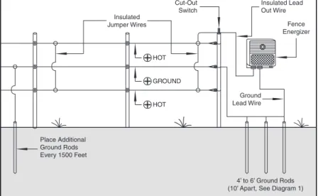
Diagram 5 – Ground Return System
For Drier Climates, Hard-to-Control Animals, Sandy Soil, Frozen Ground and Snow-Covered Ground
Place Additional Ground Rods Every 1500 Feet Insulated Jumper Wires Cut-Out Switch Insulated Lead Out Wire Fence Energizer Ground Lead Wire 4’ to 6’ Ground Rods (10’ Apart, See Diagram 1) HOT
GROUND
INSTALLING YOUR NEW ENERGIZER
BEFORE YOU START
TOOLS NEEDED
1. Screwdriver – for mounting energizer, cut-off switch and lightning choke 2. Wire cutters – to cut and strip insulation
3. Post driver – to install ground rods
4. Digital volt meter – for electric fence testing and troubleshooting
ACCESSORIES NEEDED
1. At least three galvanized ground rods – minimum 4 feet by 1/2” (minimum) diameter
2. Three ground rod clamps
3. Insulated underground hook-up wire – 50 feet (20,000V rating) 4. One energizer cut-out switch
5. Line clamps
6. One lightning choke and one lightning diverter or a combination choke and diverter
7. One surge protector (for AC-powered energizers only)
Diagram 4 – Standard Multi-Wire Systems Wire Spacing for Different Animals and Applications
INSTALLATION STEP 1
INSTALLING THE GROUND SYSTEM
The ”ground system” is a series of highly conductive rods driven into the soil and then connected by wire to the ground terminal of your fence energizer. The ground system collects electrons from the soil to complete the circuit needed for delivering an effective shock.
1. Locate an area of soil for placing ground rods that contains good conduc-tive earth (not sandy or rocky). Soil that is moist throughout the year is best. The ground system should be located within 75 feet of your fence energizer and at least 25 feet from buildings.
2. Locate ground system a minimum of 75 feet away from: a. Utility company (electric, gas, water) ground system. b. Underground water pipe
c. Metal water tanks
d. Metal siding on building (minimum 25 ft. away)
3. Drive three 4 foot by 1/2” (minimum) galvanized ground rods 10 feet apart in a straight line or a triangle pattern in the selected ground area. Leave 6 inches above the ground for securing ground clamps. Mark the area as a hazard.
4. Connect the ground rods, in a series, with one piece of continuous 10 to 14 gauge galvanized wire. The ground hook-up wire should be equal to or larger than the diameter of the fence line wire.
See Diagram on Next Page
b. Move your ground system to moist soil until the ground system voltage is below 200V.
7. Check your ground system condition with a volt meter once during the driest period and once during the wet season each year to insure adequate grounding of your electric fence.
Diagram 1 – Ground System Installation
1. 12-14 gauge galvanized fence wire.
2. Ground rods – 4 feet long by 1/2” (or more) in diameter, galvanized steel rods.
IMPORTANT: Avoid SANDY, DRY and ROCKY soil.
shorting the fence. Continue to short the fence by leaning steel posts or by making wire connections to ground at 100 yards distance or more from energizer until the fence line voltage drops below 2,000V.
4. You are now ready to test the energizer ground system. Connect one lead of the digital volt meter to a 12 inch metal stake driven into the ground 3 feet away from the last fence energizer ground rod. Connect the second lead to the ground rod furthest from the energizer. The voltage reading should ideally be zero or no more than 200V.
5. If the digital volt meter reading is under 200V, your ground system is adequate and you will get near maximum performance from your electric fence energizer.
6. If the reading is above 200V, then your ground system needs improve-ment. You must:
a. Add more ground rods connected in series, 3 feet apart. and/or
INSTALLATION STEP 2
INSTALLING THE FENCE ENERGIZER
1. Locate the energizer within 75 feet of your ground system. Use only polar-ized extension cords. Mount the fence energizer:
a. At eye level and out of the reach of small children and livestock b. Protected from weather and moisture
c. Away from all flammable materials and gasses in a well-ventilated area.
2. Before connecting the “fence” and “ground” energizer terminals, plug in or “power on” the energizer and check the output voltage at the terminals with an electric fence volt meter (use only voltmeters designed for this pur-pose). Record the voltage as a benchmark for future reference. You should see the indicator light flashing and hear a “click” at 1 to 2 second intervals.
INSTALLATION STEP 3
VERIFY THAT YOUR GROUND SYSTEM IS WORKING
The quality of your ground system is vital to maximizing the performance of your fence energizer. During dry seasons or during seasons when there is ex-cessive growth or vegetation on the fence line, it may be necessary to upgrade your ground system with extra ground rods.
To test the quality of your ground system: 1. Unplug your fence energizer.
2. Place the fence under heavy load by “shorting” the fence as follows. At a location on the fence at least 100 yards from the energizer, lean 3 or 4 steel stakes or T-posts against the “hot” wire of the fence. Alternatively, you may push several pieces of fence wire into the earth and wrap the op-posite ends around the hot wire.
3. Plug the energizer in and check the fence line voltage with a digital volt meter. You want to see that the voltage has dropped below 2,000V due to
3. UNPLUG OR TURN THE FENCE ENERGIZER OFF and then connect the “GROUND” terminal to a 10 to 14 gauge insulated lead-out wire (rated at 20,000V). The lead-out wire is also known as a “hook-up” or “under-ground fence wire”. Connect the opposite end of the wire to the closest ground rod using a ground clamp and shiny bare metal contact surfaces. Then, connect the “FENCE” terminal to a 10 to 14 gauge insulated lead-out wire (rated at 20,000V) and connect the opposite end to a fence “cut-out” switch located on the first fence post.
4. Plug the fence energizer in and measure the voltage at the “cut-out” switch before and after activating the fence. Record these voltage measurements for future use as a reference when checking the fence connection.
See Diagram on Next Page
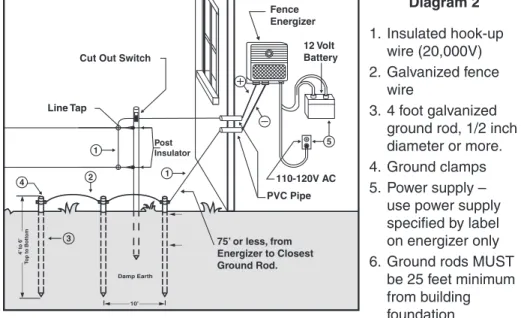
Diagram 2 1. Insulated hook-up wire (20,000V) 2. Galvanized fence wire 3. 4 foot galvanized ground rod, 1/2 inch diameter or more. 4. Ground clamps 5. Power supply –
use power supply specified by label on energizer only 6. Ground rods MUST
be 25 feet minimum from building foundation
PLEASE NOTE: The hot is either indicated by a red knob or a lighting bolt sym-bol ( ) and the ground is indicated by a black knob or an arrow symsym-bol ( ).