CONSIDERATIONS FOR THE IMPLEMENTATION OF TEST ACCESS POINTS
A BEST PRACTICE GUIDE
Tobias Planert, Benno Hornischer, SecuControl, Inc., Alexandria, VA (USA)
Dr Johannes Jenkner, Roberto Eick, SecuControl Produktions GmbH, 06333 Hettstedt (Germany) Antoni Furlani Rosa, SecuBrasil Ltda., 88050-001 Florianópolis, SC (Brazil)
Abstract — Choosing the right number and
configuration of test access points is a necessity for smooth maintenance and testing operations throughout the usage time of a panel.
This process should begin when designing the panel, with a consideration of the type and amount of test access points needed. Secondly, a choice of hardware and the associated benefits can be made (e.g. knife-blade switches or a test block / test plug solution). Once a decision about the hardware has been made, the specific configuration of the access point needs to be determined. In this step, as well as already in the previous step, possible benefits of standardization should be taken into account. Finally, a lab setup of the chosen technology and configurations can be used for a test-run, as well as advance training of personnel.
In some cases design can be done from the ground up, in others retrofit solutions are required for pre-existing installations. This paper looks at the process of designing panels with test access points from an international perspective, showcasing real-world best practice examples.
I. INTRODUCTION
On November 22, 2013, NERC adopted a new standard draft for Transmission and Generation Protection System Maintenance and Testing, PRC-005-3, which will replace the currently applicable standard version once it has been approved by FERC. [1] PRC-005-3 requires periodical testing of many substation devices and states maximum intervals between tests. Test access points are, under these circumstances, an important element to carry out this mandate, and merit a closer look at how they can best be implemented.
According to NERC PRC-005-3, the maximum maintenance / testing interval for unmonitored relays is six years, in the case of self-monitoring microprocessor relays with alarm function, twelve years. However, relay firmware updates may require some additional testing and the testing interval hence may be considerably shorter than these twelve years in practice.
II. CONSIDERATION OF THE TYPE AND AMOUNT OF TEST ACCESS POINTS NEEDED
Choosing the right number and configuration of test access points is a necessity for smooth and effortless maintenance and testing operations throughout the usage time of a panel. And the usage time can be considerable – in some cases more than 30 years. Any decision with regards to the design of test access points may therefore have long-lasting ramifications. This paper will focus on how this process works and showcase real-world examples from different countries.
We have to distinguish the process for new designs and for retrofit solutions. When designing a new panel, a consideration of the type and amount of test access points needs to be made. Depending on the relays and other IED’s used in the design, there will be a need for a certain amount of current, voltage and trip contacts. It is important to realize at this early stage which contacts will need to be available for testing – and in some cases just to be individually disconnected.
NERC requirements for periodic testing in some cases call for tests that were previously not necessary (for instance for lockout switches) for which test points might need to be added in new designs. In the case of retrofits, on the other hand, the type and amount of test access points is usually already a given and just needs to be replicated.
III. CHOICE OF HARDWARE AND ASSOCIATED BENEFITS
A key question to address at the beginning of the design process is the choice of hardware to provide the test access points. Hardware choices are influenced by various factors, including historical practice in the region, historical practice in the company, and individual usage preferences. Each design has its particular benefits.
In the United States, as well as other world regions that have been influenced by the US in important industrial areas, for instance Saudi-Arabia, a ten-pole
test switch is the prevalent solution. Test switches are offered by a number of manufacturers.
This individualized testing approach originates from the knife-blade switch design, or “FT-switch”, originally invented around the 1930s in the United States. The most common model features ten contacts. The traditional style has open metal blades, but finger-safe designs (which combine functions of a test block with individualized test access without plugs) are also available. Associated benefits are flexible disconnecting and testing of individual contacts, without the need to bring along a test plug.
Fig. 1: left to right: knife-blade test switch, finger-safe test block with individualized test access through integrated contact pins
From a global perspective, in Europe and many countries in other world regions, test block/plug systems are the most common hardware choice. Various manufacturers offer test block/plug systems, and the predominance of certain products in a region is often determined by the cultural orbit in which they operate.
Figure 2: test block/plug system (example 1)
Figure 3: test block/plug system (example 2)
Figure 4: test block/plug system (example 3)
Test block/plug systems offer the benefits of finger-safety and are well suited for standardized approaches to testing. Upon insertion of a test plug, all the contacts in the associated test block are opened. This typically happens in a pre-determined sequence to avoid accidental trips, and in many (though not all) cases with automatic shorting of current transformer circuits. Test block/plug systems are also available from a number of manufacturers, and they differ in some technical aspects. With some of these systems it is also possible to do simple testing or disconnecting using smaller test probes, operating only on subset of poles.
Many utility companies have used a particular kind of hardware for a long time, often due to the preferences and knowledge of products in their geographic area. Their workforce is used to this design, so that changes might bring along some workforce training needs.
Nevertheless, an evaluation of different product styles may prove beneficial, since benefits might outweigh the drawbacks of a change to something new.
• Test switches, or individualized test blocks, offer a greater degree of individual flexibility of use. Every contact can be opened individually, without the need to carry a test plug along.
• Test block / test plug systems generally offer benefits of standardization that test switches do not. Since the block/plug systems incorporate a sequence of operation (the contacts being opened and closed in a predefined order), their incorporation in a panel can prevent accidental trips in later operation. In some cases, test plugs can be pre-wired to the test set and the same test setup can be repeated on different devices in a substation, increasing test efficiency.
IV. DETERMINING THE CONFIGURATION OF TEST ACCESS POINTS AND BENEFITS OF STANDARDIZATION
Once the decision about the hardware has been made, the configuration of the access points has to be determined. Benefits of standardization should now also be taken into consideration, no matter which hardware is used. The following case studies will show different kinds of solutions with regards to hardware and standardization.
V. EAST KENTUCKY POWER COOPERATIVE (EKPC), WINCHESTER, KENTUCKY (USA)
East Kentucky Power Cooperative (EKPC) is one of the largest generation and transmission cooperatives in the United States. EKPC is owned by and serves 16 electric distribution cooperatives. It operates four major power plants, totaling nearly 3,000 megawatts in capacity, serves 520,000 homes and businesses in 87 Kentucky counties. EKPC operates over 2,800 miles of high-voltage transmission lines. [2]
EKPC has historically been using ten-pole test switches in a number of different configurations. Recently they decided to review their approach to test access points. It was decided to include test access points at every current, voltage or trip contact, with the exception of connectorized relays.
Looking at hardware options, EKPC wanted to stay with the individualized approach of the ten-pole test switch. However, they decided for a finger-safe test block variant to address safety concerns of exposed voltage contacts. EKPC typically mounts test switches directly underneath the device with which they are used, wiring the device to the top of the test switch. Therefore voltage blades were exposed to users in the old design, upon opening of the test switch.
In the result, EKPC standardized on three different types of ten-pole test block configurations.
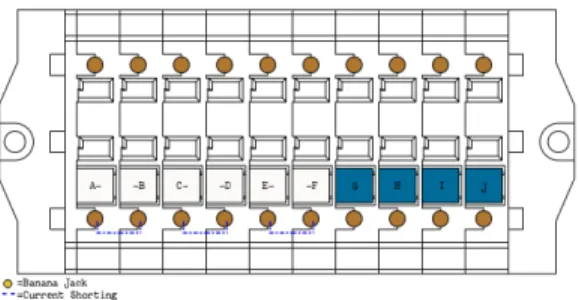
Figure 5: EKPC standard configuration for transmission relays
Figure 6: EKPC standard configuration for bus differential relays
Figure 7: EKPC standard configuration for trips Configurations one and two are electrically the same, having only a different labeling style:
• 311L and 487E relays require voltage indication, therefore blue voltage labels were assigned to them, distinguishing them from red trip labels
• 587Z and 387A relays on the other hand did not require voltage inputs. They use the same (electrical) test block style, but the voltage style contacts are labeled as trips (red labels) The third configuration is an all-purpose test block, used everywhere where only trip contacts are needed, as e.g. in the case of lockout relays.
Depending on the application, either one or more of the standard configurations are used:
• 387A relays require two CT winding inputs – therefore two standard current test blocks are associated to them
• 311L and 587Z relays only require one set of CTs, so only one test block is used
• the amount of trip contacts needed per application was already known from previous standards – every relay type is assigned either one or more trip test blocks to cover these EKPC assigns every test block to only one device. Each relay is assigned its own trip test block, or more if needed, as it is the case with some 86 lockout relays.
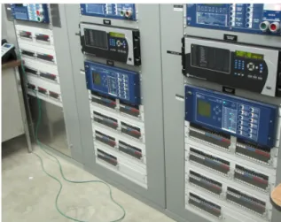
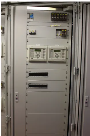
Figure 8: Example of a EKPC protection panel with standardized test access points
An important goal in the standardization on three test block styles was to minimize the amount of part numbers used, in order to keep stock numbers low, and be able to use the same test blocks on different relays and panels.
It was found that some setups had the same number of current and voltage/trip contacts, but they were previously used in different sequences. In order to standardize on fewer configurations, the sequence was changed so that the same test block can now be used for two different panel / relay applications.
Colors and inscriptions of labels were also included in the new standard. EKPC decided to use white labels for currents, blue labels for voltages and red labels for trips. For label inscriptions, it was decided to identify each contact alphabetically (A,B,C,D,… through J) in the front, since this labeling had appeared on the test switch style previously used. Integrated disconnect pins for currents, voltages and trips were labeled with their function (C--C, V, T). If any of the disconnect pins were removed, they did not have to be put back in order to match up with the A, B, C labeling, they could be reinserted in any order into the right kind of contact type (an integrated keying system prevents them from being inserted into a wrong contact type opening). The labeling system chosen by EKPC allows backwards compatibility with the previously used test switch style, while providing an easy visual indication of each test block’s function both through colors and label inscriptions.
In the course of developing the new standards, a standards document has been written to document the test block types in use, and their standardized usage. The documentation helps EKPC keep to the standard, as well as inform contractors working on behalf of the company.
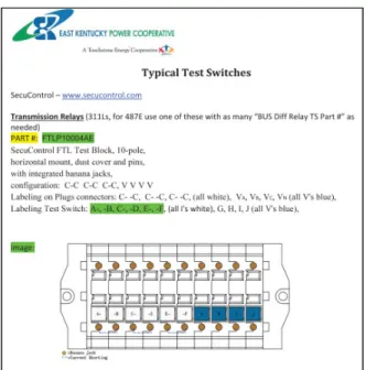
Figure 9: Excerpt from a EKPC document outlining standardized test block designs
In conclusion, the standardization on these three types of test blocks helps EKPC in the following ways:
• Staying with the individualized mode of operation of a ten-pole test switch, the approach to testing remains the same as before • Safety concerns about exposed voltage contacts
have been addressed with a new design • Standardizing on three test block styles,
technicians encounter fewer different configurations across the system, making testing easier, faster and safer
• Standardization on specific labeling colors and inscriptions aids test technicians
• With few standard test block designs, it is less costly to keep a small stock of each style for quick replacements
VI. TEXAS NEW MEXICO POWER COMPANY (TNMP), LEWISVILLE, TEXAS (USA)
Texas New Mexico Power Company (TNMP) is an electricity transmission and distribution company serving 230,000 customers throughout Texas. The subsidiary of PNM Resources is based in Lewisville, Texas. [3]
TNMP went through several phases in their process to standardize on a test access point solution. Having originally used ten-pole test switches as a standard solution, TNMP became interested in a test block/plug systems for their testing needs. The reasons for the
decision of choosing a different technology were diverse.
As the major reason, the general safety aspect was pointed out. While the test block/plug system increases the technician’s safety through finger-safe design and integrated CT-shorting, he can focus all his attention on the actual test procedure. Having less things to worry about was the first step to increase the efficiency of the test procedure. The second factor to significantly reduce test duration was the ability to use a prewired test plug to test multiple relays. The wiring of a test set to the panel used to be calculated with one man-hour of work per relay before the change. Now, the new solution only requires the test set to be wired once to the test plug which then can be inserted into all test blocks of the same configuration. This improvement reduced the necessary time to test one substation from a full day to a few hours.
In the first phase of installing the new equipment, TNMP created standards in various different sizes, closely aligned with specific relays and their functions.
Figure 10: Example of TNMP test block installations This solution provided many improvements, including the safety and efficiency benefits mentioned, as well as considerable panel space savings. However it became a challenge to keep track of many different test plugs needed in TNMP’s substations. This led TNMP to further optimize the layout of test access points, and decrease their number of standard configurations.
In the second standardization phase, TNMP continued using the test block/plug system, now using almost exclusively three ten-pole configurations. The test blocks are operated by ten-pole test plugs, and optionally with individual test probes. Separating trip contacts and current & voltage contacts in two
individual test blocks/plugs, TNMP clearly defined a two step test procedure. The first step, insertion of the trip plug and disconnecting all trip contacts, eliminates the risk of false trips entirely, then voltages and currents are opened (/shorted) in the second step, using the second plug.
The focus on only few standardized configurations significantly reduced the amount of needed test plugs, and allowed using the same bundle of test equipment throughout the entire TNMP system. A test crew can now head for a (sometimes quite remote) substation, knowing exactly what they will see in the panel. TNMP accomplished a standardized panel design all over the system, which increased the technicians understanding of the system and decreased the need to double check wiring or connection drawings. This not only made training of new technicians quicker, it also increased the confidence of the technician in his work, even when performing tests during service.
VII. 50HERTZ TRANSMISSION GMBH, BERLIN (GERMANY)
50Hertz Transmission GmbH (50Hertz) is a German transmission utility. Based in Berlin, 50Hertz operates and maintains 9,840 km of high-voltage transmission lines throughout northern and eastern Germany, reliably supplying power to 18 million people. [4]
50Hertz realizes test access points via a test block/plug system and a standard for test interfaces defined in a technical specification, published by the German VDE (Association for Electrical, Electronic and Information Technologies). [5] The predecessor company of 50Hertz already used the same standard, which had originally been introduced in the 1970’s.
The VDE standard was written with different types of protection in mind, including e.g. distance protection, differential protection, transformer protection and line differential protection. Standardized test block/plug arrangements were designed which included specific amounts of currents, voltages and trip circuits, matching the protection requirements. In order to keep the amount of test block configurations low, many test block configurations are designed to be used for different applications, even if this meant that in some applications not all of the test block contacts are connected. Later additional applications with digital protection were added to the existing standard, for instance line differential protection with distance protection.
Standard sizes of test blocks and plugs according to the VDE standard are 7-pole, 14-pole and 19-pole.
Examples for some typical configurations and some of their uses are:
A7: configuration: C-C V V T T T
• single system current-, voltage-, and power relays
• wattmetric ground fault detection • transient earth fault relays
B14: configuration: C-C-C-C V V V V T T T T T T • overcurrent time protection
• directional overcurrent time protection • distance protection and directional overcurrent
protection C19: configuration:
C-C C-C C-C C-C V T T T T T T T T T T • digital overcurrent time protection
• busbar protection
Figure 11: Excerpt from VDE technical specification for test interfaces for protection, showing configuration “C14”, with electrical setup at the
bottom, and different associated uses on top
50Hertz uses the 7-, 14- and 19-pole standard test block/plug sizes as defined by VDE, mainly for distance protection, differential protection, transformer protection and line differential protection, as well as other uses. These standard test access points are in use in almost all of 50Hertz’s substations (the only exception being substations that were acquired from other utilities, which will be changed to the standard when overhauled), and with every digital relay. Testing of secondary circuits is normally performed by 50Hertz’ own employees. If external companies are used, 50Hertz specifies all testing details, including the software to be used. In cases of connections to wind farms or other generation plants, 50Hertz performs testing only if the cabinets have been built according to their standards (since testing would otherwise be too work intensive).
Figure 12: 50Hertz standardized protection panel for transformer protection
Test efficiency and time savings are of high importance to 50Hertz. Due to low numbers of qualified personnel, testing is only possible to the extent required with a highly standardized test process. Test efficiency is achieved by using standardized test access points, test templates and partly automated adaptation of settings for test routines (saved by the test software).
Currently, high investments are being made in the high voltage transmission grid, leading to a high number of commissioning tests and functional testing, and further increasing the need for test efficiency.
Figure 13: 50Hertz standardized protection panel for line differential protection
Test intervals are specified in a technical directive, and they are frequent. For digital protection for lines and transformers, the maximum interval is 4 years, and for some other types of digital protection it is only 2 years. Electromechanical protection needs to be tested twice as often, or more, depending on its’ condition. (Approximately 90% of the protection in the 380/220 kV grid of 50Hertz is digital protection.) Even though 50Hertz performs tests in relatively short time intervals they decided to always run the same, comprehensive test, using an automated test program. The time a test takes cannot be reduced much through using fewer test variables, because times for disconnects, test setup, connection of the test set and drive to the test location always remain the same.
In addition to protection relays a number of other devices are part of the protection system (time relays, communication devices, terminal blocks, wire
connections etc), and issues tend to be more often associated with these other elements than with the protection relays. The frequent and regular test intervals help 50Hertz identify such issues.
Training of new employees is done using real protection cabinets, but only when these are taken out of service. This on-the-job training takes place in teams, with at least one experienced test technician always part of the team.
The standardization on VDE configurations for test access points across all of their substations has brought 50Hertz many benefits, among them:
• high work safety for test technicians working on transformer circuits, through the finger-safe design of the test blocks, and automated CT shorting upon test plug insertion
• very efficient test process, since all test blocks are wired in the same way across the system for the same function, the connections of currents, voltages (coming from the test set) and trips is given and technicians can concentrate on the test itself
• protection from unintended trips due to the automated sequence of operation built into the test block/plug system, opening trips before other contacts upon test plug insertion
• possibility to test during operation, an important point for 50Hertz since it is becoming less often possible to take assets out of operation
• all components used across the system, including test blocks/plugs, are the same everywhere, and certified in-house by 50Hertz, making the technicians’ work easier
• testing of all protection relays is homogenous across the system
• uniform test templates and documentation are used within the company
• standard templates exist for all types of protection & control cabinets
• standardized parts can easily be reordered, and spare parts stocked
• contractors are familiar with the company standards, reducing costs
VIII. COMPANHIA PARANAENSE DE ENERGIA (COPEL), CURITIBA, PARANÁ (BRAZIL)
Companhia Paranaense de Energia (Copel) serves over 4.1 million customers in the Brazilian state of Paraná. Copel operates 21 generating plants with an installed capacity of 4,756 MW, 2,174 km of transmission lines and 32 transmission substations, as
well as 187,310 km of distribution lines and 361 distribution substations. [6]
In Copel’s case, concerns arose because of exposed energized parts of a previously used test switch solution, and quality issues. This motivated a change in Copel’s specifications towards a finger-safe test block design.
Standard configurations had already been established and used with the previous test access points, therefore a direct retrofit solution was required. Copel’s standards are 10-pole units, almost exclusively three configu-rations. These test block standards are applied to all substations, new designs as well as retrofits. Copel did not want to make changes to existing designs and projects, and keep the test process in place as it existed.
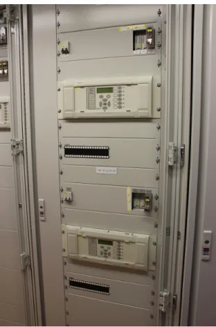
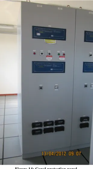
Figure 14: Copel protection panel
Since Copel had been working with similar products before they did not put together a first test project, but started using the new style test blocks right away.
Dimensions were identical, therefore no modifications to panel designs or arrangements were needed. Workforce training was barely required since the usage of the new product was considered simple. Acceptance by the technical personnel was good.
IX. CONCLUSION
In times of NERC PRC-005, the decision of how to integrate test access points becomes more important. With increased testing requirements, well thought-out and standardized test access points can make the job of the test technician both safer and more efficient.
Different technologies for test access points are available. Test block/plug systems and the more individualized approach of test switches or individualized test blocks both have their merits. For each utility the answer what is best for them may be a different one, taking into consideration their own specific requirements (e.g. test intervals and procedures) and legacy.
The real-world examples from Kentucky, Texas, Germany and Brazil show different approaches, yet all of them experience benefits through thoughtful implementation of test access points. In addition to safety and test efficiency, considerations may include, for instance, the possibility to test during operation, intuitive labeling, simplification of work with contractors, and reduction of required product stock.
If considering a new technology, a first installation of the chosen hardware and configurations in either a test environment or a limited first application can allow users to gather feedback, which may lead to further improvements of the design.
ACKNOWLEDGMENT
The authors are grateful for the extensive feedback from our contacts at East Kentucky Power Cooperative, Texas New Mexico Power, 50Hertz Transmission GmbH and Companhia Paranaense de Energia, which made this paper possible.
REFERENCES [1] NERC. [Online]. Available:
http://www.nerc.com/pa/Stand/Pages/Project2007172Protection SystemMaintenanceand-TestingPhase2ReclosingRelays [2] EKPC. [Online]. Available:
http://www.ekpc.coop/overview.html
[3] TNMP. [Online]. Available: www.tnmp.com/about [4] 50Hertz. [Online]. Available:
http://www.50hertz.com/de/unternehmen.htm [5] VDE. [Online]. Available:
http://www.vde.com/de/fg/ETG/Arbeitsgebiete/sua/ Aktuelles/Oeffentlich/Seiten/Pruefstecksysteme.aspx [6] Copel. [Online]. Available:
http://www.copel.com/hpcopel/english/copel.jsp
BIOGRAPHIES
Tobias Planert received his Diplom (masters level) degree in Language, Economic and Cultural Studies from the University of Passau, Germany, in 2005. Tobias worked for a consulting firm in Duesseldorf, Germany, from 2005-2006. He has worked for SecuControl, Inc. since 2007, specializing in advanced test interfaces for secondary injection testing.
Benno Hornischer received his master level degree (Diplom Ing.) in Industrial Engineering from the Technical University Braunschweig, Germany, in 2012. He joined SecuControl in Germany after his graduation. Benno now works as a sales engineer for SecuControl, Inc., focusing on the US and East Asian markets.
Dr. Johannes Jenkner received his M.S. in Meteorology (2005) from the University of Innsbruck, Austria and his S.D. in Atmospheric and Climate Sciences (2008) from the Swiss Federal Institute of Technology, Switzerland. He did research work for Columbia University, New York, and the University of British Columbia, Canada. He has worked for SecuControl Produktions GmbH since 2013. His current research interests include weather impacts on power generation and consumption, innovative test designs for protective panels and data analysis in smart grid solutions.
Roberto Eick received his B.S. in Electrical Engineering (2012) from Santa Maria Federal University, Brazil. Following three months work experience at SecuBrasil Ltda., Roberto joined SecuControl Produktions GmbH in 2013. His research interests include test interface applications and protective relay panel design.
Antoni Furlani Rosa received his Bachelor degree in Electrical Engineering from Santa Catarina State University, Brazil in 2013. He did his graduation internship with SecuControl Produktions GmbH in Germany and then joined SecuBrasil as an application engineer.