Fast Design of Jerusalem-Cross Parameters by Equivalent Circuit Model and
Least-Square Curve Fitting Technique
Hsing-Yi Chen, Tsung-Han Lin, and Pei-Kuen Li
Department of Communications EngineeringYuan Ze University, Chung-Li, Taoyuan, 32003, Taiwan
[email protected], [email protected], [email protected]
Abstract ─ Based on an equivalent circuit model, the
least-square curve fitting technique is proposed to quickly design optimum values of geometrical parameters of a dual-band Jerusalem-cross element for arbitrarily specifying any dual resonant frequencies. The validity of the least-square curve fitting technique is checked by comparing geometrical parameters and dual resonant frequencies of six Jerusalem-cross grids obtained by the proposed technique with those obtained by the improved empirical model and measurement method. Design of dual-band Jerusalem-cross slots is also conducted by the proposed technique. Simulation results of reflection and dual resonant frequencies of Jerusalem-cross slots designed by the proposed technique are also validated by measurement data.
Index Terms ─ Dual-band Jerusalem-cross element,
least-square curve fitting, reflection, transmission.
I. INTRODUCTION
Frequency selective surface (FSS) has been extensively studied for many decades [1-32]. It has many applications in polarizers [1], antenna designs [2-10], transmission improvement for signals through energy-saving glass [11-14], artificial magnetic conductor (AMC) designs [15-17], spatial microwave and optical filters [18-25], absorbers [26-31], and planar metamaterials [32]. The FSS is usually formed by periodic arrays of metallic patches or slots of arbitrary geometries. A FSS with periodic arrays of metallic patches or slots exhibits total reflection or total transmission in the neighborhood of the geometric resonant frequency, respectively. Typical FSS geometries are designed by dipoles, rings, square loops, fractal shapes, etc. Most of these FSSs are used to deal with reflection and transmission problems at a single resonant frequency. It is rather difficult to design FSS elements that offer dual-band responses.
Several numerical methods have been used to design FSS parameters such as method of moments (MoM) [18], finite-difference time-domain (FDTD) method
[33-35], and finite-element method (FEM) [36]. These methods have a tedious computation procedure which involves many electromagnetic equations governing FSS theory. In recent years, many electromagnetic simulation commercial software packages are available for the
design of FSS parameters, such as Ansoft’s HFSS,
Ansoft’s Designer, and CST Microwave Studio. These
commercial software packages are easily used to design FSS parameters. However, the design process of a FSS element using the commercial software package can be divided into preliminary and fine tune steps. In the preliminary design steps, various critical geometrical dimensions of a FSS element are well investigated through parametric study using a full-wave model simulation. Based on preliminary study, the final design can be achieved through fine tuning the critical geometrical parameters to obtain the desired resonant frequencies. This is a non-efficient and labor intensive process due to trial-and-error tests and heavy computational works. Alternatively, the equivalent circuit method [37-39] is much simpler than numerical methods for the design of FSS parameters. In this method, the segments of the FSS structure are modeled as capacitive and inductive components in a transmission line [37-38]. Limitation of the equivalent circuit method is that it can be used only for normal incidence and without substrates.
In this paper, we propose the least-square curve fitting technique [40] to quickly obtain optimum values of geometrical parameters of a dual-band Jerusalem-cross element for arbitrarily specifying any dual resonant frequencies. In the design process, an equivalent circuit model of the frequency characteristic for normal wave incidence [38] is introduced to facilitate the optimum design of a Jerusalem-cross element. In simulations, the transmission and reflection of Jerusalem-cross elements are obtained by using the Ansoft high-frequency structure simulator (HFSS, Ansoft, Pittsburgh, PA). Simulation results of geometrical parameters and dual resonant frequencies of Jerusalem-cross grids obtained by the proposed technique are compared with those
1054-4887 © 2015 ACES
Submitted On: September 20, 2013 Accepted On: May 25, 2015
obtained by the improved empirical model and measurement method presented in the literature [38]. Dual-band Jerusalem-cross slots designed by the proposed technique are also presented. Simulation results of reflection and dual resonant frequencies of Jerusalem-cross slots are validated by measurement data.
II. EQUIVALENT CIRCUIT MODEL OF
JERUSALEM-CROSS GRIDS
The equivalent circuit model of Jerusalem-cross grids is a very useful technique to quickly predict the resonant frequencies of their structures. Figure 1 shows a FSS element constructed with Jerusalem-cross grids and its geometrical parameters p, w, s, h, and d. Where p is the periodicity of a unit cell, w is the width of the conductive strip, s is the separation distance between adjacent units, h is the width of the end caps of the Jerusalem-cross, and d is the length of the end caps of the Jerusalem-cross. Based on Langley and Drinkwater’s
studies [38], for any array of thin, continuous, infinitely long, perfectly conducting Jerusalem-cross FSS for normal incidence EM waves, the equivalent circuit model can be presented as shown in Fig. 2. The series resonant circuit L1C1 is used to generate the lower resonant frequency f1 (in reflection band), the series resonant circuit L2C2 is used to produce the higher resonant frequency f2, and the capacitor Ct is used to create the transmission band frequency ft. The normalized (with respect to the free-space impedance and admittance, respectively) inductive reactance XL1 and capacitive susceptance BC1 of the equivalent circuit model are given as follows:
1 1 1 1 1 1 ( , , ) [ ( ) ( , , )], L w p X ω L F p w λ n β G p w λ λ (( w)) (1) where O and Zare the wavelength and angular frequency of the first resonant frequency f1, respectively:
1 4 2 2 2 1 1 1 1 2 4 6 2 6 1 1 1 1 ( , , ) (1 ) [(1 )( ) 4 ] 1 4 , 2 (1 ) ( )( ) 2 4 2 8 w w w w w w w w G p w λ β β A A β A A β β β β A A β A A u (2) 1 1 2 1 1 1, 1 ( ) A A p λ (3) sin( ), 2 w π w β p (4) 1 1 1 1 1 1 1 1 1 4 4(2 ) ( , , ) ( , , ) 4 [ ( ) ( , , )] 4(2 ) [ ( ) ( , , )], c s pd d h s B ω C F p s λ F p p d λ p p d n β G p s λ λ h s n β G p p d λ λ (βss)) ( ) ( pd (ββpd)) ( ) (5) where 1 4 2 2 2 1 1 1 1 2 4 6 2 6 1 1 1 1 ( , , ) (1 ) [(1 )( ) 4 ] 1 4 , 2 (1 ) ( )( ) 2 4 2 8 s s s s s s s s G p s λ β β A A β A A β β β β A A β A A u (6) 1 4 2 2 2 1 1 1 1 2 4 6 2 6 1 1 1 1 ( , , ) (1 ) [(1 )( ) 4 ] 1 4 , 2 (1 ) ( )( ) 2 4 2 8 pd pd pd pd pd pd pd pd G p p d λ β β A A β A A β β β β A A β A A u (7) sin( ), 2 s π s β p (8) (p-d) sin[ ]. 2 pd π β p (9)
The first resonant frequency f1 can be obtained from L1 and C1 expressed by:
1 1 1 1 . 2 f π L C (10)
The normalized inductive reactance XL2 of the equivalent circuit model is given as following:
2 2 2 2 2 2 2 / 2 2 2 1 ( , 2 , ) ( , , ) 2 2 2 [ ( ) ( , 2 , )] 2 [ ( ) ( , , )], 4 2 L hs p d p X ω L F p h s λ F w λ p d n β G p h s λ λ p p n β G w λ λ (βhshs) ( ))) ( )) ( / 2 ( / 2/ 2/ 2 ( )) (( / 2)) (11)
where O and Zare the wavelength and angular frequency of the second resonant frequency f2, respectively: 2 4 2 2 2 2 2 2 2 2 4 6 2 6 2 2 2 2 ( , 2 , ) (1 ) [(1 )( ) 4 ] 1 4 , 2 (1 ) ( )( ) 2 4 2 8 hs hs hs hs hs hs hs hs G p h s λ β β A A β A A β β β β A A β A A u (12) 2 4 2 2 2 2 2 3 3 2 3 3 2 4 6 2 2 2 2 6 2 3 3 2 3 3 ( , , ) 2 (1 ) [(1 )( ) 4 ] 1 4 , 2 (1 ) ( )( ) 2 4 2 8 p p p p p p p p p G wλ β β A A β A A β β β β A A β A A u (13) 2 2 2 2 1 1, 1 ( ) A A p λ (14) 3 3 2 2 1 1, 1 ( ) 2 A A p λ (15)
(2 ) sin[ ], 2 hs π h s β p (16) 2 w sin( ). p π β p (17)
The normalized capacitive susceptance BC2 of the equivalent circuit model is given as following:
2 2 2 2 2 2 8(2 ) ( , , ) 8(2 ) [ ( ) ( , , )], c pd h s B ω C F p p d λ p h s n β G p p d λ λ ( pd (βpd)) ( ) (18) where 2 4 2 2 2 2 2 2 2 2 4 6 2 6 2 2 2 2 ( , , ) (1 ) [(1 )( ) 4 ] 1 4 , 2 (1 ) ( )( ) 2 4 2 8 pd pd pd pd pd pd pd pd G p p d λ β β A A β A A β β β β A A β A A u (19)
Epd, A2+, and A2- are given in (9) and (14), respectively. The second resonant frequency f2 can be obtained from L2and C2 expressed by:
2 2 2 1 . 2 f π L C (20)
Equations (1)-(20) are valid when p<O2 and p>d,
whereO2 is the wavelength of the second resonant
frequency f2. In band-stop electromagnetic shielding
applications, the resonant frequencies f1 and f2 are specified first and then all parameters of the unit should be determined. However, to simultaneously determine all parameters of one Jerusalem-cross unit for arbitrarily given resonant frequencies f1 and f2 is not an easy job. In the following section, the least-square curve fitting technique will be applied to calculate all parameters of any Jerusalem-cross element for arbitrarily given dual resonant (rejection) frequencies f1 and f2.
Fig. 1. Geometrical parameters of a FSS constructed with Jerusalem-cross grids.
Fig. 2. An equivalent circuit model for Jerusalem-cross grids.
III. LEAST-SQUARE CURVE FITTING
TECHNIQUE
The equivalent circuit model of a thin, continuous, and infinitely long array of Jerusalem-cross grids is presented in Fig. 2. In the band-stop electromagnetic shielding design, critical geometrical parameters of Jerusalem-cross grids p, w, s, h, and d should be solved for arbitrarily given dual resonant frequencies f1 and f2. Basically, resonant frequencies f1 and f2 are two nonlinear functions expressed by (10) and (20) in terms of geometrical parameters p, w, s, h, and d. The method of differential corrections, together with Newton’s iterative method [40], can be used to fit the nonlinear functions f1 and f2. The differential corrections method approximates the nonlinear functions with a linear form that is more convenient to use for an iterative solution. By estimating approximate values of the unknown coefficients A1(0), (0) 2 , A A3(0), (0) 4 ,
A andA5(0),and expanding (10) and (20) in a Taylor’s series with only the first-order terms retained, we obtain:
(0) 1 (0) 1 (0) 1 (0) 1 1 1 2 3 1 2 3 (0) (0) 1 1 4 5 4 5 Δ ( ) Δ ( ) Δ ( ) Δ ( ) Δ ( ) , f f f f f A A A A A A f f A A A A w w w w w w w w w w (21) (0) 2 (0) 2 (0) 2 (0) 2 2 1 2 3 1 2 3 (0) (0) 2 2 4 5 4 5 Δ ( ) Δ ( ) Δ ( ) Δ ( ) Δ ( ) , f f f f f A A A A A A f f A A A A w w w w w w w w w w (22)
where A1=p, A2=w, A3=s, A4=h, and A5=d. The superscript (0) is used to indicate values obtained after substituting the first guess (A1(0),
(0) 2 , A A3(0), (0) 4 , A andA5(0)), for the unknown parameters in (10) and (20). Equations (21) and (22) are two linear functions of the correction terms Δ ,A1 Δ ,A2 Δ ,A3 Δ ,A4 andΔ ,A5 and hence the least-square curve fitting method can be used directly to determine these correction terms. The correction terms, when added to the first guess, give an improved approximation of the unknown coefficients, i.e.,
(1) (0) 1 1 Δ ,1 A A A (1) (0) 2 2 Δ ,2 A A A (1) (0) 3 3 Δ ,3 A A A (1) (0) 4 4 Δ ,4 A A A and (1) (0) 5 5 Δ .5 A A A When the improved estimates (1) 1 , A (1) 2 , A (1) 3 , A (1) 4 , A and (1) 5 A are subsequently substituted as new estimates of the unknown coefficients, the Taylor’s series reduces to:
(1) 1 (1) 1 (1) 1 (1) 1 1 1 2 3 1 2 3 (1) (1) 1 1 4 5 4 5 Δ ( ) Δ ( ) Δ ( ) Δ ( ) Δ ( ) , f f f f f A A A A A A f f A A A A w w w w w w w w w w (23) (1) 2 (1) 2 (1) 2 (1) 2 2 1 2 3 1 2 3 (1) (1) 2 2 4 5 4 5 Δ ( ) Δ ( ) Δ ( ) Δ ( ) Δ ( ) , f f f f f A A A A A A f f A A A A w w w w w w w w w w (24)
where (1) 1
f and (1)
2
f as well as their derivatives are obtained by substituting the values of (1)
1 , A (1) 2 , A (1) 3 , A (1) 4 ,
A and A5(1) in (10) and (20), respectively. Again, the correction terms ΔA1, Δ ,A2 Δ ,A3 Δ ,A4 and ΔA5 are determined using the least-square curve fitting method. The procedure is continued until the solution converges to within a specified accuracy. The criterion of best fit of the technique of least-square curve fitting is that the sum of the squares of the errors be a minimum expressed by:
2 2 1 2 1 1 N N i i i i
S
¦ ¦
ε
ε
= minimum, (25) where the term errors 21 i
ε and 2 2 i
ε mean the difference between the measured (observed) values of the first and second resonant frequencies
f
1M( )
i
and f2M( )i and computed values from (23) and (24) for the ith case, respectively. N is the total number of cases. Substituting (23) and (24) into (25), the result yields:2 2 1 1 2 2 1 1
[
( )
( )]
[
( )
( )] .
N N M M i iS
¦
f
i
f i
¦
f
i
f i
(26) A necessary condition that a minimum for the error function S exists is that the partial derivatives with respect to each of the correction terms Δ ,A1 ΔA2, ΔA3,4
ΔA,and ΔA5 be zero. For example, in the first iteration:
(0) (0) (0) 1 1 1 1 1 1 1 (0) (0) (0) 1 1 1 2 3 4 2 3 4 (0) (0) (0) 1 2 5 2 2 1 5 (0) (0) (0) 2 2 2 1 2 3 1 2 3 4 2 ( ) [ ( ) Δ ( ) (Δ ) Δ ( ) Δ ( ) Δ ( ) Δ ( ) ] 2 ( ) [ ( ) Δ ( ) Δ ( ) Δ ( ) Δ ( N M i j j N M i j f f S f i f A A A A f f f A A A A A A f f A f i f A A f f f A A A A A A f A w w w w w w w w w w w w w w w w w w w w w w w
¦
¦
(0) (0) 2 2 5 4 5 ) Δ ( ) ] 0, f A A A w w w (27)where j= 1, 2, 3, 4, and 5. Equation (27) can be expressed as a matrix equation. One can easily solve for the correction terms Δ ,A1 ΔA2, ΔA3, ΔA4, and ΔA5 in (28) by Gaussian elimination method.
Equation (28) is a very sensitive equation because the partial derivatives of resonant frequencies f1 and f2 withrespect to each of the parameters A1=p, A2=w, A3=s,
A4=h, and A5=d still can generate nonlinear functions such as square root, natural logarithm, sine, and cosine. Therefore, the values of parameters p, w, s, h, and d should be limited to an acceptable range in the Newton’s iterative process. In order to obtain a stable iterative process, the parameters p,w,s,h, andd are automatically checked and set to 0.75O2<p<O2, 0.1O2<w<O2, 0.03O2<s<O2, 0.03O2<h<O2, and 0.4O2<d<O2 in each iteration, respectively:
(0) 2 (0) 2 (0) (0) (0) (0) 1 2 1 1 2 2 1 1 1 1 1 1 5 1 1 5 (0) (0) (0) (0) (0) (0) 1 1 2 2 1 1 1 2 1 1 2 1 1 2 5 [( ) ] [( ) ] . . . ( ) ( ) ( ) ( ) ( ) ( ) ( ) ( ) ... ( ) ( ) N N N N i i i i N N N i i i f f f f f f A A A A A A f f f f f f A A A A A A w w w w w w w w w w w w w w w w w w w w w w w w
¦
¦
¦
¦
¦
¦
¦
2 (0) 2 (0) 1 2 5 ( ) ( ) . . . . . . . . N i f f A A w w w w¦
(0) (0) (0) (0) (0) 2 (0) 2 1 1 2 2 1 2 1 5 1 1 5 1 1 5 1 5 1 2 3 4 . . ( ) ( ) ( ) ( ) . . . [( ) ] [( ) ] Δ Δ Δ Δ Δ N N N N i i i i f f f f f f A A A A A A A A A A A ª º « » « » « » « » « » « » « » « » « w w w w w w » « » w w w w w w « » « » ¬ ¼ u¦
¦
¦
¦
(0) (0) (0) (0) 1 2 1 1 2 2 1 1 1 1 (0) (0) (0) (0) 1 2 1 1 2 2 1 2 1 2 (0) (0) (0) (0) 1 2 1 1 2 2 1 3 1 3 5 ( ) [ ( ) ] ( ) [ ( ) ] ( ) [ ( ) ] ( ) [ ( ) ] ( ) [ ( ) ] ( ) [ ( ) N N M M i i N N M M i i N N M M i i f f f i f f i f A A f f f i f f i f A A f f f i f f i f A A w w w w w w ª º w w « » « » w w « » w w « » « » « » ¬ ¼¦
¦
¦
¦
¦
¦
(0) (0) (0) (0) 1 2 1 1 2 2 1 4 1 4 (0) (0) (0) (0) 1 2 1 1 2 2 1 5 1 5 ] . ( ) [ ( ) ] ( ) [ ( ) ] ( ) [ ( ) ] ( ) [ ( ) ] N N M M i i N N M M i i f f f i f f i f A A f f f i f f i f A A ª º « » « » « » « » « » « » « » « » « w w » « » « w w » « w w » « » « w w » ¬ ¼¦
¦
¦
¦
(28)The partial derivatives of resonant frequencies f1 and
f2 with respect to each of the parameters can be obtained by the following two equations:
3 1 2 1 1 1 1 1 1 1 ( ) ( ), 4 i i i f C L L C L C A π A A w w w w w w (29) 3 2 2 2 2 2 2 2 2 1 ( ) ( ), 4 i i i f C L L C L C A π A A w w w w w w (30)
where A1=p, A2=w, A3=s, A4=h, and A5=d. The partial derivatives of inductances and capacitances L1, L2, C1, and C2are with respect to each of the parameters p, w, s, h, and d as shown in APPENDIX.
IV. VALIDATION OF LEAST-SQUARE
CURVE FITTING
In order to validate the least-square curve fitting technique, dimensions of six Jerusalem-cross grids with thin, infinitely long, and perfectly conducting strips listed in the literature [38] are checked by the proposed technique. Simulation results of transmission for six Jerusalem-cross grids generated by the least-square curve fitting technique are studied by the commercial software package HFSS. Comparisons of two specific resonant frequencies f1 and f2 obtained by the least-square curve fitting technique, improved empirical
model [38], and measurement [38] are listed in Table 1. Obviously, the six sets of dimensions obtained by the improved empirical model are different from those obtained by the least-square curve fitting technique. But it is found that simulation results of the resonant frequencies f1 and f2 for the six sets of parameters generated by the least-square curve fitting technique make a good agreement with those obtained by the empirical model and measurement available in the literature [38]. Table 1 illustrates that the set of dimensions of a Jerusalem-cross grid for any specific dual resonant frequencies f1 and f2 is not unique. Table 2 shows the comparison of computational time obtained by the least-square (LS) curve fitting technique and HFSS implemented with genetic algorithm (GA) [41] for design of Jerusalem-cross parameters in a personal computer. It is illustrated that the proposed method provides a fast solution for design of Jerusalem-cross parameters. The frequency responses of transmission of the six Jerusalem-cross grids, their dimensions obtained by the least-square curve fitting technique, are also shown in Figs. 3-8. These Jerusalem-cross grids have a transmission of more than -30 dB at resonant frequencies
f1 and f2. The average bandwidths obtained at resonant frequencies f1 and f2 are more than 12% with a transmission of -10 dB.
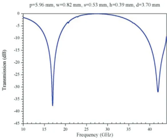
Table 1: Comparisons of resonant frequencies f1 and f2 obtained by the least-square (LS) curve fitting technique (Figs. 3-8), improved empirical model (IEM) [38], and measurement (M) [38] for different Jerusalem-cross grids for normal wave incidence No. Dimensions (mm) [38] Dimensions (mm) (LS) f1(GHz) f2(GHz) p w d h s p w d h s M [38] IEM [38] LS M [38] IEM [38] LS 1 5.82 0.8 4.05 0.4 0.3 7.05 1.06 3.63 0.23 0.24 14.1 14.0 14.9 (Fig. 3) 41.5 42.7 40.5 (Fig. 3) 2 5.82 0.8 4.6 0.42 0.27 7.11 0.82 3.9 0.73 0.28 12.8 12.8 12.6 (Fig. 4) 38.3 38.0 37.6 (Fig. 4) 3 6.5 0.9 4.95 0.3 0.21 7.86 0.92 4.5 0.86 0.3 11.6 11.3 10.9 (Fig. 5) 33.7 34.2 33.6 (Fig. 5) 4 5.84 1.42 4.5 0.32 0.38 5.96 0.82 3.70 0.39 0.53 17.3 17.0 17.0 (Fig. 6) 43.0 41.8 41.9 (Fig. 6) 5 6.3 1.18 4.8 0.39 0.41 6.7 0.94 4.15 0.41 0.40 14.3 14.2 14.5 (Fig. 7) 38.3 38.2 37.4 (Fig. 7) 6 5.98 1.18 4.6 0.42 0.38 7.00 1.0 3.75 0.35 0.34 14.9 15.0 14.8 (Fig. 8) 40.1 40.0 40.1 (Fig. 8)
Fig. 3. The frequency response of transmission of the sample No. 1 listed in Table 1.
Fig. 4. The frequency response of transmission of the sample No. 2 listed in Table 1.
Fig. 5. The frequency response of transmission of the sample No. 3 listed in Table 1.
Fig. 6. The frequency response of transmission of the sample No. 4 listed in Table 1.
Fig. 7. The frequency response of transmission of the sample No. 5 listed in Table 1.
Fig. 8. The frequency response of transmission of the sample No. 6 listed in Table 1.
Table 2: Comparison of computational time obtained by the least-square (LS) curve fitting technique and HFSS implemented with genetic algorithm (GA) for design of Jerusalem-cross parameters
V. JERUSALEM-CROSS SLOTS
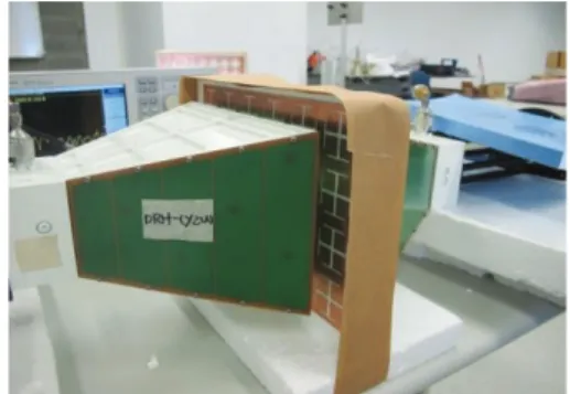
In order to improve EM transmission, aperture types of FSSs may be used to provide a better signal transmission at specific frequencies while also providing an isolation capability for unwanted EM noises. With all conducting and non-conducting areas interchanged, a Jerusalem-cross slot (a complementary Jerusalem-cross grid) can be used to reverse the transmission and reflection coefficients of the Jerusalem-cross grid [38]. We arbitrarily specify two pairs of dual resonant frequencies of (2.45, 5.8) and (3.96, 7.92) GHz to design two Jerusalem-cross slots by the least-square curve fitting technique. The Jerusalem-cross slots are constructed on a copper foil with a thickness of 0.05 mm. The specific frequencies of (2.45, 5.8) and (3.96, 7.92) GHz are in the Bluetooth (2.4-2.48 GHz), wireless local area network (IEEE802. 11a, upper band 5.725-5.825 GHz), and ultra-wideband (low-frequency band 3.168-4.752 GHz and high-frequency band 6.336-9.504 GHz) applications. Simulation results of reflection at frequencies (2.45, 5.8) and (3.96, 7.92) GHz will be investigated by checking the reflection with better than 10 dB return loss for the two Jerusalem-cross slots. The simulation results of frequency response of reflection will also be checked by measurement data. Measurement data of reflection of the two Jerusalem-cross slots are obtained by using an Anritsz37369C Vector Network Analyzer and a pair of horn antennas operating at frequencies of 1-18 GHz as shown in Fig. 9. The frequency responses of reflection of the first and second Jerusalem-cross slots with parameters (p=40.0 mm, w=5.4 mm, s=4.5 mm, h=2.1 mm, d=29.0 mm) and (p=28.5 mm, w=5.6 mm, s=3.8 mm, h=1.2 mm, d=21.6 mm) are shown in Figs. 10 and 11, respectively. From Figs. 10 and 11, it is shown that simulation results of frequency responses of reflection make a good agreement with those obtained by measurements. Figure 10 shows that the first Jerusalem-cross slot has a reflection of more than -30 dB at frequencies of 2.45 and 5.8 GHz. Simulation and measurement results of bandwidths at frequencies of 2.45 and 5.8 GHz have an average value of 15% with a reflection of -10 dB. From Fig. 11, the second Jerusalem-cross slot has a reflection
of more than -40 dB at frequencies of 3.96 and 7.92 GHz. Simulation and measurement of bandwidths at frequencies of 3.96 and 7.92 GHz have an average value of 14.5% with a reflection of -10 dB. These bandwidths are enough to effectively transmit the Bluetooth, wireless local area network, and ultra-wideband signals.
Fig. 9. Measurement setup.
Fig. 10/ The frequency response of reflection of the first Jerusalem-cross slot.
Fig. 11. The frequency response of reflection of the second Jerusalem-cross slot.
No. LS HFSS with GA 1 3 s 1 day 7 hr 27 m 21 s 2 8 s 2 day 18 hr 28 m 13 s 3 6 s 3 day 16 hr 45 m 17 s 4 13 s 4 day 13 hr 24 m 49 s 5 4 s 1 day 19 hr 14 m 29 s 6 9 s 3 day 23 hr 58 m 38 s
VI. CONCLUSION
In this paper, we propose the least-square curve fitting technique to quickly obtain optimum values of geometrical parameters of a dual-band Jerusalem-cross grid with thin, infinitely long, and perfectly conducting strips. Based on circuit model, the least-square curve fitting technique can provide a quick and accurate design of a dual-band Jerusalem-cross grid for arbitrarily specifying any dual resonant frequencies. The validity of the proposed technique has been checked by comparing two specific resonant frequencies f1 and f2 with those obtained by the improved empirical model and measurement method. The proposed method provides a fast solution for design of Jerusalem-cross parameters. The proposed technique can also be used to optimally design a dual-band Jerusalem-cross slot for arbitrarily specifying any two resonant frequencies. However, the proposed technique presented in this paper does not include the substrate. It is expected that the presence of the dielectric substrate will shift the resonant frequencies downwards. In the future works, the shifting factor will be further studied on the transmission and reflection of an energy-saving glass coated with a metallic oxide layer on one side of ordinary float glass which is widely used in modern building.
APPENDIX
This Appendix illustrates the partial derivatives of inductances and capacitances L1, L2, C1, and C2 with respect to each of the parameters p, w, s, h, and d as following: 1 1 1 1 1 1 1 1 1 1 [ ( ( , , )] ( , , ) 1 [ ], w w w L L n β G p w λ A p ω λ β G p wλ p ω λ β p p w w w w w w w w ( w (βw ( (31) where 2cos( ), 2 2 w β πw πw p p p w w (32) 1 2 ( , , ) 1 , 2 n d d n d G G G G G p wλ p p p G w w w w w w (33) 4 2 2 2 1 1 1 1 (1 ) [(1 )( ) 4 ], 4 w n w w β G β AA β A A (34) 2 4 6 2 6 1 1 1 1 (1 ) ( )( ) 2 , 4 2 8 w w w d w w β β β G β AA β A A (35) 4 2 1 1 2 2 2 3 1 1 1 1 4 2 1 1 1 1 2 1 1 1 1 2(1 )( 2 )[(1 )( ) 4 4 ] (1 ) [ ( ) (1 )( ) 4 4 4 8 ], n w w w w w w w w w w w w w G β β β β A A p p β β A A β β A A p β A A A β A p p p β A β A β A A p p w w w w w w w w w w w w w w w w (36) 3 5 1 1 4 6 2 1 1 6 1 6 1 1 1 5 1 1 1 3 (2 2 ) ( ) 2 4 ( )( ) 2 8 2 2 12 , d w w w w w w w w w w w w w G β β β β β β A A p p p β β A A β p p A A β A β A p p β β A A p w w w w w w w w w w w w w w w w (37) 3 2 1 1 2 2 1 1 1 2 [1 ( ) ] ( ), 2 A A p p p p λ λ w w w w (38) 1 1 1 2 1 1 ( , , ) 1 [ w ], w β L L p G p wλ A w ω λ β w w w w w w w w w w (39) where cos( ), 2 2 w β π πw w p p w w (40) 1 2 ( , , ) 1 , 2 n d d n d G G G G G p w λ w w w G w w w w w w (41) 4 2 1 1 2 2 2 3 1 1 1 1 1 1 2(1 )( 2 )[(1 )( ) 4 4 ] (1 ) [ ( ) 8 ], n w w w w w w w w w w G β β β β A A w w β β A A β β A A w β β A A w w w w w w w w w (42) 3 5 1 1 5 1 1 1 2 3 (2 2 ) ( ) 4 12 , d w w w w w w w w G β β w w β β β β A A w β β A A w w w w w w w w w (43) 1 1 3 0, L L A s w w w w (44) 1 1 4 0, L L A h w w w w (45) 1 1 5 0, L L A d w w w w (46) 1 1 1 1 1 1 1 1 1 ( , , ) 4 1 [ 4(2 ) 1 [ ( , , ) ], s s pd pd β C C d G p s λ A p ω λ β p p β h s ω λ β p G p p d λ p w w w w w w w w w w w w (47) where 2cos( ), 2 2 s β πs πs p p p w w (48) 2 ( ) cos[ ], 2 2 pd β πd π p d p p p w w (49)
1 2 ( , , ) 1 , 2 sn sd sd sn sd G G G G G p s λ p p p G w w w w w w (50) 4 2 2 2 1 1 1 1 (1 ) [(1 )( ) 4 ], 4 s sn s s β G β AA β A A (51) 2 4 6 2 1 1 6 1 1 (1 ) ( )( ) 4 2 8 2 , s s s sd s s β β β G β A A β A A (52) 4 2 1 1 2 2 2 3 1 1 1 1 4 2 1 1 1 1 2 1 1 1 1 2(1 )( 2 )[(1 )( ) 4 4 ] (1 ) [ ( ) (1 )( ) 4 4 4 8 ], sn s s s s s s s s s s s s s G β β β β A A p p β β A A β β A A p β A A A β A p p p β A β A β A A p p w w w w w w w w w w w w w w w w (53) 3 5 1 1 4 6 2 1 1 6 1 6 1 1 1 5 1 1 1 2 3 (2 2 ) ( ) 4 ( )( ) 2 8 2 2 12 , sd s s s s s s s s s s s s s G β β p p β β β β A A p β β A A β p p A A β A β A p p β β A A p w w w w w w w w w w w w w w w w (54) 1 2 ( , , ) 1 , 2 pdn pdd pdd pdn pdd G G G G G p p d λ p p p G w w w w w w (55) 4 2 2 2 1 1 1 1 (1 ) [(1 )( ) 4 ], 4 pd pdn pd pd β G β AA β A A (56) 2 4 6 2 1 1 6 1 1 (1 ) ( )( ) 4 2 8 2 , pd pd pd pdd pd pd β β β G β A A β A A (57) 4 2 1 1 2 2 2 3 1 1 1 1 4 2 1 1 1 1 2 1 1 1 1 2(1 )( 2 )[(1 )( ) 4 4 ] (1 ) [ ( ) (1 )( ) 4 4 4 8 ], pdn pd pd pd pd pd pd pd pd pd pd pd pd pd G β β β β A A p p β β A A β β A A p β A A A β A p p p β A β A β A A p p w w w w w w w w w w w w w w w w (58) 3 5 1 1 4 6 2 1 1 6 1 6 1 1 1 5 1 1 1 2 3 (2 2 ) ( ) 4 ( )( ) 2 8 2 2 12 , pdd pd pd pd pd pd pd pd pd pd pd pd pd pd G β β p p β β β β A A p β β A A β p p A A β A β A p p β β A A p w w w w w w w w w w w w w w w w (59) 1 1 2 0, C C A w w w w w (60) 1 1 1 3 1 1 1 1 1 ( , , ) 4 1 [ 4 [ ( ) ( , , )], s s pd β C C d G p s λ A s ω λ β s s n β G p p d λ ω λ w w w w w w w w (((ββpdpd))) (61) where cos( ), 2 2 s β πs πs s p p w w (62) 1 2 ( , , ) 1 , 2 sn sd sd sn sd G G G G G p s λ s s s G w w w w w w (63) 4 2 1 1 2 2 2 3 1 1 1 1 1 1 2(1 )( 2 )[(1 )( ) 4 4 ] (1 ) [ ( ) 8 ], sn s s s s s s s s s s G β β β β A A s s β β A A β β A A s β β A A s w w w w w w w w (64) 3 5 1 1 5 1 1 1 2 3 (2 2 ) ( ) 4 12 , sd s s s s s s s s G β β s s β β β β A A s β β A A s w w w w w w w w (65) 1 1 1 4 1 1 8 [ ( pd) ( , , )], C C nβ G p p d λ A h ω λ w w w w (((ββpdpd))) (66) 1 1 5 1 1 1 ( , , ) 4(2 ) 1 [ pd ], pd C C A d β G p p d λ h s ω λ β d d w w w w w w w w (67) where ( ) cos[ ], 2 2 pd β π π p d d p p w w (68)
1 2 ( , , ) 1 , 2 pdn pdd pdd pdn pdd G G G G G p p d λ d d d G w w w w w w (69) 4 2 1 1 2 2 2 3 1 1 1 1 1 1 2(1 )( 2 )[(1 )( ) 4 4 ] (1 ) [ ( ) 8 ], pdn pd pd pd pd pd pd pd pd pd pd G β β β β A A d d β β A A β β A A d β β A A d w w w w w w w w (70) 3 5 1 1 5 1 1 1 2 3 (2 2 ) ( ) 4 12 , pdd pd pd pd pd pd pd pd pd G β β d d β β β β A A d β β A A d w w w w w w w w (71) 2 2 2 1 2 2 2 2 2 2 2 2 2 2 2 ( , 2 , ) 1 [ ] 2 1 [ ( ( , , )] 4 2 ( , , ) 1 2 [ ], 4 hs hs p p p β L L d G p h s λ A p ω λ β p p p n β G w λ ω λ p G wλ β p ω λ β p p w w w w w w w w w w w w ( 2 ( 222 ( 2 (72) where 2 (2 ) (2 ) cos[ ], 2 2 hs β π h s π h s p p p w w (73) 2 2 cos[ ], p β πw πw p p p w w (74) 2 2 ( , 2 , ) 1 , 2 hsn hsd hsd hsn hsd G G G G G p h s λ p p p G w w w w w w (75) 4 2 2 2 2 2 2 2 (1 ) [(1 )( ) 4 4 ], hs hsn hs hs β G β A A β A A (76) 2 4 6 2 2 2 6 2 2 (1 ) ( )( ) 4 2 8 2 , hs hs hs hsd hs hs β β β G β A A β A A (77) 4 2 2 2 2 2 2 3 2 2 2 2 4 2 2 2 2 2 2 2 2 2 2 2(1 )( 2 )[(1 )( ) 4 4 ] (1 ) [ ( ) (1 )( ) 4 4 4 8 ], hsn hs hs hs hs hs hs hs hs hs hs hs hs hs G β β β β A A p p β β A A β β A A p β A A A β A p p p β A β A β A A p p w w w w w w w w w w w w w w w w (78) 3 5 2 2 4 6 2 2 2 6 2 6 2 2 2 5 2 2 1 2 3 (2 2 ) ( ) 4 ( )( ) 2 8 2 2 12 , hsd hs hs hs hs hs hs hs hs hs hs hs hs hs G β β p p β β β β A A p β β A A β p p A A β A β A p p β β A A p w w w w w w w w w w w w w w w w (79) 3 2 2 2 2 2 2 2 1 2 [1 ( ) ] ( ), 2 A A p p p p λ λ w w w w (80) 2 2 2 2 2 2 2 ( , , ) 1 2 , 2 p wn p wd p wd p wn p wd G G p G G G w λ p p p G w w w w w w (81) 4 2 2 2 2 2 3 3 2 2 3 3 (1 ) [(1 )( ) 4 4 ], p p wn p p β G β A A β A A (82) 2 2 2 4 6 2 2 2 2 3 3 6 2 3 3 (1 ) 4 ( )( ) 2 8 2 , p p wd p p p p β G β β β A A β A A (83) 4 2 2 2 2 2 2 3 3 2 2 2 2 3 2 2 2 2 2 3 3 4 2 3 3 2 3 2 3 2 3 2 3 2 2 3 3 2(1 )( 2 )[(1 )( ) 4 4 ] (1 ) [ ( ) (1 )( ) 4 4 4 8 ], p wn p p p p p p p p p p p p p G β β β β A A p p β β A A β β A A p β A A p p A A β A β A p p β β A A p w w w w w w w w w w w w w w w w (84) 2 2 2 2 3 5 2 2 2 3 3 4 6 2 2 2 3 3 2 6 3 6 3 2 3 2 3 2 5 2 3 3 1 2 3 (2 2 ) ( ) 4 ( )( ) 2 8 2 2 12 , p wd p p p p p p p p p p p p p G β β p p β β β β A A p β β A A β p p A A β A β A p p β β A A p w w w w w w w w w w w w w w w w (85)
3 2 3 3 2 2 2 2 1 [1 ( ) ] ( ), 2 2 2 A A p p p p λ λ w w w w (86) 2 2 2 2 2 2 2 2 ( , , ) 1 2 [ ], 4 p p p G w λ β L L p A w ω λ β w w w w w w w w w w (87) where 2 cos[ ], p β πw πw w p p w w (88) 2 2 2 2 2 2 2 ( , , ) 1 2 , 2 p wn p wd p wd p wn p wd G G p G G G w λ w w w G w w w w w w (89) 4 2 2 2 2 2 2 3 3 2 2 2 2 2 2 2 3 2 2 3 3 2 2 3 3 2(1 )( 2 )[(1 )( ) 4 4 ] (1 ) [ ( ) 8 ], p wn p p p p p p p p p p G β β β β A A w w β A A β β β A A w β β A A w w w w w w w w w (90) 2 2 2 2 3 5 2 2 2 3 3 2 5 2 3 3 1 2 3 (2 2 ) ( ) 4 12 , p wd p p p p p p p p G β β w w β β β β A A w β β A A w w w w w w w w w (91) 2 2 2 3 2 2 ( , 2 , ) 1 [ ], 2 hs hs β L L d G p h s λ A s ω λ β s s w w w w w w w w (92) where (2 ) cos[ ], 2 hs β π π h s s p p w w (93) 2 2 ( , 2 , ) 1 , 2 hsn hsd hsd hsn hsd G G G G G p h s λ s s s G w w w w w w (94) 4 2 2 2 2 2 2 3 2 2 2 2 2 2 2(1 )( 2 )[(1 )( ) 4 4 ] (1 ) [ ( ) 8 ], hsn hs hs hs hs hs hs hs hs hs hs G β β β β A A s s β β A A β β A A s β β A A s w w w w w w w w (95) 3 5 2 2 5 2 2 1 2 3 (2 2 ) ( ) 4 12 , hsd hs hs hs hs hs hs hs hs G β β s s β β β β A A s β β A A s w w w w w w w w (96) 2 2 4 2 2 2 ( , 2 , ) 1 [ ], 2 hs hs L L A h β G p h s λ d ω λ β h h w w w w w w w w (97) where (2 ) cos[ ], hs β π π h s h p p w w (98) 2 2 ( , 2 , ) 1 , 2 hsn hsd hsd hsn hsd G G G G G p h s λ h h h G w w w w w w (99) ] 8 ) ( [ ) 1 ( ] 4 ) )( 4 1 )[( 2 )( 1 ( 2 2 2 2 2 3 2 2 2 2 2 2 2 4 2 h A A A A h A A A A h h G hs hs hs hs hs hs hs hs hs hs hsn w w w w w w w w
E
E
E
E
E
E
E
E
E
E
(100) 3 5 2 2 5 2 2 1 2 3 (2 2 ) ( ) 4 12 , hsd hs hs hs hs hs hs hs hs G β β h h β β β β A A h β β A A h w w w w w w w w (101) 2 2 2 5 2 2[
(
)
( , 2
,
)],
2
hsL
L
d
n
β
G p
h s λ
A
d
ω λ
w
w
w
w
(
(
(
β
hshs)
)
)
)
(102) 2 2 1 2 2 2 ( , , ) 8(2 ) 1 [ pd ], pd C C A p β G p p d λ h s ω λ β p p w w w w w w w w (103) where 2 2 2 2 2 2 2 ( , , ) 1 , 2 pdn pdd pdd pdn pdd G G G G G p p d λ p p p G w w w w w w (104)4 2 2 2 2 2 2 2 3 2 2 2 2 4 2 2 2 2 2 2 2 2 2 2 2(1 )( 2 )[(1 )( ) 4 4 ] (1 ) [ ( ) (1 )( ) 4 4 4 8 ], pdn pd pd pd pd pd pd pd pd pd pd pd pd pd G β β β β A A p p β β A A β β A A p β A A A β A p p p β A β A β A A p p w w w w w w w w w w w w w w w w (105) 2 3 5 2 2 4 6 2 2 2 6 2 6 2 2 2 5 2 2 1 2 3 (2 2 ) ( ) 4 ( )( ) 2 8 2 2 12 , pdd pd pd pd pd pd pd pd pd pd pd pd pd pd G β β p p β β β β A A p β β A A β p p A A β A β A p p β β A A p w w w w w w w w w w w w w w w w (106) 2 2 2 0, C C A w w w w w (107) 2 2 3 2 2 2 8 [ ( pd) ( , , )], C C A s n β G p p d λ ω λ w w w w (((ββpdpd))) (108) 2 2 2 4 2 2 16 [ ( pd) ( , , )], C C n β G p p d λ A h ω λ w w w w (((ββpdpd))) (109) 2 2 5 2 2 2 ( , , ) 8(2 ) 1 [ pd ], pd C C A d β G p p d λ h s ω λ β d d w w w w w w w w (110) where 2 2 2 2 2 2 2 ( , , ) 1 , 2 pdn pdd pdd pdn pdd G G G G G p p d λ d d d G w w w w w w (111) 4 2 2 2 2 2 2 2 3 2 2 2 2 2 2 2(1 )( 2 )[(1 )( ) 4 4 ] (1 ) [ ( ) 8 ], pdn pd pd pd pd pd pd pd pd pd pd G β β β β A A d d β β A A β β A A d β β A A d w w w w w w w w (112) 2 3 5 2 2 5 2 2 1 2 3 (2 2 ) ( ) 4 12 . pdd pd pd pd pd pd pd pd pd G β β d d β β β β A A d β β A A d w w w w w w w w (113)
ACKNOWLEDGMENT
The authors would like to thank the National Science Council of the Republic of China (ROC) for the financial support of this research under the contract of NSC 102-2221-E-155-019.
REFERENCES
[1] R. Ulrich, “Far-infrared properties of metallic
mesh and its complementary structure,” Infrared
Phys., vol. 7, no. 1, pp. 37-50, 1967.
[2] B. A. Munk, R. J. Luebbers, and R. D. Fulton,
“Transmission through a 2-layer array of loaded
slots,” IEEE Trans. Antennas Propag., vol. AP22, no. 6, pp. 804-809, Nov. 1974.
[3] F. Yang and Y. Rahmat-Samii, “Reflection phase
characterizations of the EBG ground plane for low
profile wire antenna applications,” IEEE Trans.
Antennas Propag., vol. 51, no. 10, pp. 2691-2703,
Oct. 2003.
[4] Y. Zhang, J. von Hagen, M. Younis, C. Fischer,
and W. Wiesbeck, “Planar artificial magnetic
conductors and patch antennas,” IEEE Trans.
Antennas Propag., vol. 51, no. 10, pp. 2704-2712,
Oct. 2003.
[5] X. L. Bao, G. Ruvio, M. J. Ammann, and M. John,
“A novel GPS patch antenna on a fractal hi
-impedance surface substrate,” IEEE Antennas
Wireless Propag. Lett., vol. 5, pp. 323-326, 2006. [6] H. Mosallaei and K. Sarabandi, “Antenna
miniaturization and bandwidth enhancement using
a reactive impedance substrate,” IEEE Trans.
Antennas Propag., vol. 52, no. 9, pp. 2403-2414,
Sep. 2004.
[7] R. F. J. Broas, D. F. Sievenpiper, and E.
Yablonovitch, “A high-impedance ground plane
applied to a cellphone handset geometry,” IEEE
Trans. Microw. Theory Tech., vol. 49, no. 7, pp.
1262-1265, Jul. 2001.
[8] A. P. Feresidis, G. Goussetis, S. Wang, and J. C.
Vardaxoglou, “Artificial magnetic conductor
surfaces and their application to low-profile
high-gain planar antennas,” IEEE Trans. Antennas
Propag., vol. 53, no. 1, pp. 209-215, Jan. 2005. [9] H. Y. Chen and Y. Tao, “Bandwidth enhancement
of a U-slot patch antenna using dual-band frequency selective surface with double
rectangular ring elements,” Microw. Opt. Technol. Lett., vol. 53, no. 7, pp. 1547-1553, Jul. 2011. [10] H. Y. Chen and Y. Tao, “Performance
improvement of a U-slot patch antenna using a dual-band frequency selective surface with
modified Jerusalem cross elements,” IEEE Trans.
Antennas Propag., vol. 59, no. 9, pp. 3482-3486,
Sep. 2011.
[11] M. Philippakis, C. Martel, D. Kemp, M. C. S. M. R. Allan, S. Appleton, W. Damerell, C. Burton, and E. A. Parker, Application of FSS Structures to Selectively Control the Propagation of Signals into
and out of Buildings, ERA Technology,
Leatherhead, Surrey, UK, Tech. Rep., 2004. [12] M. Gustafsson, A. Karlsson, A. P. P. Rebelo, and
B. Widenberg, “Design of frequency selective
windows for improved indoor outdoor
communication,” IEEE Trans. Antennas Propag.,
vol. 54, no. 6, pp. 1897-1900, Jun. 2006.
[13] G. I. Kiani, L. G. Osslon, A. Karlsson, and K. P. Esselle, “Transmission of infrared and visible wavelengths through energy-saving glass due to etching of frequency-selective surfaces,” IET
Microw. Antennas Propag., vol. 4, pp. 955-961,
2010.
[14] G. I. Kiani, L. G. Osslon, A. Karlsson, K. P. Esselle, and M. Nilsson, “Cross-dipole bandpass frequency selective surface for energy-saving glass
used in building,”IEEE Trans. Antennas Propag., vol. 59, no. 2, pp. 520-525, Feb. 2011.
[15] D. J. Kern, D. H. Werner, A. Monorchio, L.
Lanuzza, and M. J. Wilhelm, “The design synthesis
of multiband artificial magnetic conductors using high impedance frequency selective surfaces,”
IEEE Trans. Antennas Propag., vol. 53, no. 1, pp.
8-17, Jan. 2005.
[16] J. McVay, N. Engheta, and A. Hoorfar, “High
impedance metamaterial surfaces using
Hilbert-curve inclusions,” IEEE Microw. Wireless
Compon. Lett., vol. 14, pp. 130-132, 2004.
[17] J. Bell and M. Iskander, “A low-profile archimedean spiral antenna using an EBG ground
plane,” IEEE Antennas Wireless Propag. Lett., vol. 3, pp. 223-226, 2004.
[18] R. Mittra, C. H Chan, and T. Cwik, “Techniques
for analyzing frequency selective surfaces - a
review,” Pro. IEEE, vol. 76, no. 12, pp. 1593-1615, Dec. 1988.
[19] F. R. Yang, K. P. Ma, Y. Qian, and T. Itoh, “A
uniplanar compact photonic-bandgap (UC-PBG) structure and its applications for microwave
circuits,” IEEE Trans. Microw. Theory Tech., vol. 47, no. 8, pp. 1509-1514, Aug. 1999.
[20] K. Sarabandi and N. Behdad, “A frequency selective surface with miniaturized elements,”
IEEE Trans. Antennas Propag., vol. 55, no. 5, pp.
1239-1245, May 2007.
[21] T. Kamgaing and O. M. Ramahi, “Design and
modeling of high-impedance electromagnetic surfaces for switching noise suppression in power
planes,” IEEE Trans. Electromagn. Compat., vol. 47, no. 3, pp. 479-489, Aug. 2005.
[22] T. K. Wu, “Four-band frequency selective surface
with double-square-loop patch elements,” IEEE Trans. Antennas Propag., vol. 42, no. 12, pp. 1659-1663, Dec. 1994.
[23] H. L. Liu, K. L. Ford, and R. J. Langley, “Design
methodology for a miniaturized frequency selective surface using lumped reactive components,” IEEE Trans. Antennas Propag., vol. 57, no. 9, pp. 2732-2738, Sep. 2009.
[24] R. R. Xu, H. C. Zhao, Z. Y. Zong, and W. Wu,
“Dual-band capacitive loaded frequency selective surfaces with close band spacing,” IEEE Microw. Wireless Compon. Lett., vol. 18, no. 12, Dec. 2008. [25] G. I. Kiani, K. L. Ford, K. P. Esselle, A. R. Weily,
C. Panagamuwa, and J. C. Batchelor, “Single-layer
bandpass active frequency selective surface,”
Microw. Opt. Technol. Lett., vol. 50, no. 8, pp.
2149-2151, Aug. 2008.
[26] G. I. Kiani, K. L. Ford, K. P. Esselle, A. R. Weily,
and C. J. Panagamuwa, “Oblique incidence
performance of a novel frequency selective surface absorber,” IEEE Trans. Antennas Propag., vol. 55, no. 10, pp. 2931-2934, Oct. 2007.
[27] B. A. Munk, P. Munk, and J. Pryor, “On designing Jaumann and circuit analog absorbers (CA
absorbers) for oblique angle of incidence,” IEEE
Trans. Antennas Propag., vol. 55, no. 1, pp.
186-193, Jan. 2007.
[28] A. K. Zadeh and A. Karlsson, “Capacitive circuit
method for fast and efficient design of wideband
radar absorbers,” IEEE Trans. Antennas Propag., vol. 57, no. 8, pp. 2307-2314, Aug. 2009.
[29] A. Itou, O. Hashimoto, H. Yokokawa, and K.
Sumi, “A fundamental study of a thin wave
absorber using FSS technology,” Electron.
Commun. Jpn., vol. 87, pt. 1, pp. 77-86, 2004.
[30] A. Itou, H. Ebara, H. Nakajima, K. Wada, and O.
Hashimoto, “An experimental study of a wave
absorber using a frequency-selective surface,”
Microw. Opt. Technol. Lett., vol. 28, pp. 321-323,
2001.
[31] G. I. Kiani, A. R. Weily, and K. P. Esselle, “A
novel absorb/transmit FSS for secure indoor
wireless networks with reduced multipath fading,”
IEEE Microw. Wireless Compon. Lett., vol. 16, no.
[32] N. Engheta and R. W. Ziolkowski, Metamaterials:
Physics and Engineering Explorations,
Hoboken/Piscataway, NJ, Wiley-IEEE Press, 2006.
[33] R. Baggen, M. Martinez-Vazquez, J. Leiss, and S. Holzwarth, “Comparison of EBG substrates with and without vias for GALILEO/GPS applications,”
In Proc. EuCAP 2007, 2nd European Conf.
Antennas Propag., Edinburgh, UK, 2007.
[34] Y. Fan, B. L. Ooi, H. D. Hriston, and M. S. Leong,
“Compound diffractive lens consisting of Fresnel zone plate and frequency selective screen,”IEEE
Trans. Antennas Propag., vol. 58, no. 6, pp.
1842-1847, Jun. 2010.
[35] P. Harms, R. Mittra, and W. Ko, “Implementation of the periodic boundary-condition in the finite-difference time-domain algorithm for FSS structures,” IEEE Trans. Antennas Propag., vol. 42, no. 9, pp. 1317-1324, Sep. 1994.
[36] J. L. Volakis, T. Ozdemir, and J. gong, “Hybrid finite-element methodologies for antennas and scattering,” IEEE Trans. Antennas Propag., vol. 45, no. 3, pp. 493-507, Mar. 1997.
[37] T. W. Leonard and J. W. Cofer, “A new equivalent circuit representation for the Jerusalem cross,” in
Proc. IEE Int. Conf. Antennas and Propagation,
London, England, vol. 2, pp. 65-69, 1978.
[38] R. J. Langley and A. J. Drinkwater, “Improved empirical model for the Jersalem cross,” IEE Proc., vol. 129, Pt. H., no. 1, pp. 1-6, Feb. 1982.
[39] M. Hosseinipanah and Q Wu, “Equivalent circuit model for designing of Jerusalem cross-based artificial magnetic conductors,”Radioeng., vol. 18, no. 4, pp. 544-550, Dec. 2009.
[40] L. H. Lafara, Computer Method for Science and
Engineering, New York: Hayden, pp. 148-157,
1973.
[41] S. H. Sun and B. Z. Wang, “Parameter optimization based on GA and HFSS,”J. Electron. Sci. Technol. China, vol. 3, no. 1, pp. 45-47, Mar. 2005.
Hsing-Yi Chen was born in
Taiwan, in 1954. He received the B.S. and M.S. degrees in Electrical Engineering in 1978 and 1981 from Chung Yuan Christian University and National Tsing Hua University, respectively. He received the Ph.D. degree in Electrical Engineering from University of Utah, Salt Lake City, Utah in 1989. He joined the faculty of the Department of Electrical Engineering, Yuan Ze University, Taiwan, in September 1989. He was the Chairman of Electrical Engineering
from 1996 to 2002, the Chairman of Communications Engineering from 2001 to 2002, the Dean of Engineering College from 2002 to 2006, the Dean of Electrical and Communication Engineering College from 2006 to 2012, and the Dean of Research and Development Office from 2012 to 2013. Currently, he is the Dean of General Affairs Office, Yuan Ze University. His current interests include electrostatic discharge, electromagnetic scattering and absorption, waveguide design, radar systems, electromagnetic compatibility and interference, bioelectromagnetics, electromagnetic radiation hazard protection, and applications of frequency selective surface.
He is a Member of Phi Tau Phi. He was also a Member of the editorial board of the Journal of Occupational
Safety and Health from 1996 to 1997. He was elected an
Outstanding Alumnus of the Tainan Second High School in 1995. He has been the recipient of numerous awards including the 1990 Distinguished Research, Service, and Teaching Award presented by the Yuan Ze University, the 1999 and 2002 YZU Outstanding Research Award, and the 2005 Y. Z. Hsu Outstanding Professor Award for Science, Technology & Humanity Category. He was awarded Chair Professor by Far Eastern Y. Z. Hsu Science and Technology Memorial Foundation in 2008.
His name is listed in Who’s Who in the World in 1998.
Tsung-Han Lin was born in
Taiwan, in 1988. He received the B.S. degree in Electronic Engineering from Chung Yuan Christian University in 2010. He is currently working toward the M.S. degree in Communications Engineering at Yuan Ze University, Taiwan. His research interests include patch antenna design, frequency selective surfaces, and numerical computation of electromagnetics.
Pei-Kuen Li was born in Taiwan, in 1988. He received the B.S. and M.S. degrees in Communications Engineering from Yuan Ze University in 2011 and 2013, respectively. His research interests include electrostatic discharge, patch antenna design, electromagnetic compatibility and interference, wireless communications, and numerical computation of electromagnetics.