Service Delivery Training Module 3 of 4
MINISTRY OF LOCAL GOVERNMENT AND PROVINCIAL COUNCILS
MINISTRY OF LOCAL GOVERNMENT AND PROVINCIAL COUNCILS
ROAD AND DRAINAGE
MAINTENANCE
Service Delivery Training Module 3 of 4
CONTENTS
Preface . . . | 1
Introduction . . . | 3
Session 1: Sustainable Road Maintenance Management . . . | 5
1.1 Why Maintenance of Roads is Required . . . | 5
1.2 Management Tasks . . . | 5
1.3 Classification of Maintenance . . . | 5
1.4 Organization and Responsibilities . . . | 6
1.5 Storing and Handling Materials . . . | 7
1.6 Allocation of Resources: Personnel, Plant Equipment and Tools in Road Maintenance . . . | 7
1.7 Road Inventory . . . .| 8
1.8 Inspection and Assessment of Road Condition . . . | 9
1.9 Prioritization of Work and Spot Improvement . . . | 11
1.10 Method of Undertaking Maintenance Work . . . | 11
1.11 Safety Measures and Traffic Control . . . | 13
Session 2: Effective Road Maintenance Techniques . . . | 19
2.1 General . . . | 19
Session 3: Maintenance of Road Drainage . . . | 20
3.1 General . . . | 20
3.2 Objectives of Road Drainage and the Maintenance Task . . . | 21
3.3 Drainage of Road Surface . . . | 21
3.4 Maintenance Methods – Roadside Areas . . . | 27
Session 4: Maintenance of Unpaved Roads . . . | 34
4.1 Grading / Dragging . . . | 34
4.2 Labour-Based Reshaping . . . | 40
4.3 Patching . . . | 43
4.4 Re-Gravelling (Labour and Tractors) . . . | 46
4.5 Dragging (Improvised Substitute for Mechanized Grading) . . . | 50
Session 5: Maintenance of Paved Roads . . . | 52
5.1 General Repairs . . . | 53
5.2 Techniques . . . | 53
5.3 Resources for General Repair . . . | 58
5.4 Maintenance Methods . . . | 59
5.5 Surface Dressings Mechanized . . . | 65
5.6 Maintenance Methods . . . | 71
Session 6: Low Cost Technique . . . | 75
6.1 Introduction . . . | 75
6.2 Low Cost Construction Techniques . . . | 75
6.3 Quality Control Techniques . . . | 77
PREFACE
The Asia Foundation (TAF) implemented the Transparent Accountable Local Governance (TALG) Program with financial support from the United States Agency for International Development (USAID) from January 2005 - September 2007. The Foundation’s main counterparts were the Ministry of Local Government and Provincial Councils and the Sri Lanka Institute of Local Governance. The International City/County Management Association (ICMA) and Environmental Management Lanka (EML) provided additional technical assistance and support.
The TALG Program developed a number of training modules and publications as part of its institutional strengthening programme for Local Authorities (LAs) in Sri Lanka. Each of the TALG training modules was used to train officials in thirty-five LAs in Southern, Eastern, Central, North Western, North Central and Uva provinces. These were very successful in promoting effective, transparent and accountable local governance. Preparing the training modules was a painstaking process and support from the Australian Agency for International Development (AusAID) enabled The Asia Foundation to complete and publish this and the other publications in the series.
INTRODUCTION
Through the interventions made by the Foundation for the betterment of the Local Governance system in Sri Lanka, publications were developed in the following areas:
• Citizen Participation • Local Planning • Service Delivery • Financial Management • Policy and Regulations
These publications range from one-page documents of Leading Practices to Training Modules. Major categories of the publications are:
• Training Modules • Guidebooks
• Reports and Documents • Video Films
• Computer Applications
TALG developed many training modules mainly in the areas of Financial Management and Service Delivery. Road and Drainage Maintenanceis Module 3 under Service Delivery Training. Other training modules in the series include:
Module 1: Solid Waste Collection and Transport Module 2: Solid Waste Reduction
Module 4: Solid Waste Planning and Disposal
In addition to these training modules, TALG developed video films showing successful solid waste management (SWM) initiatives implemented by the Sri Lankan and regional LAs.
Users should note that there are a range of TALG publications including Technology of Participation and Resource Directory for Local Authorities that can be used by LAs to create an enabling environment for improved road and drainage maintenance.
About this Training Module
Module 3: Road and Drainage Maintenance
In Sri Lanka, National and Provincial road authorities are responsible for the maintenance of main roads, whereas minor roads which are mainly gravel roads, are part of the LA’s area of responsibility. In addition to SWM, LAs spend a considerable amount of money on the maintenance of roads and drainage facilities. LAs are only able to maintain a fraction of minor roads due to lack of resources and 'know how'. This module targets low cost but effective maintenance practices, and management procedures to ensure better roads and drainage maintenance.
What is Inside this Module
The publications developed by TALG can be used by different users, ranging from beginners to practitioners, those working in LAs and for those working as partners of LAs. This publication contains all of the resources developed for the delivery of a two-day workshop in Road and Drainage Maintenance.
This training module provides comprehensive and detailed learning materials on Road and Drainage Maintenance and although it is specifically intended for Technical Officers and others engaged in road and drainage maintenance at supervisory level, it can be used as reference material for all practitioners in LAs and as background information for trainers. This module provides practical guidance for: (1) sustainable road maintenance management and (2) effective road and drainage maintenance techniques on all road components under the LA responsibility. The attention of the module is primarily focused on the use of direct labour or small-scale labour contractors for the execution of maintenance operations. Although most of the local bodies possess little or no basic machinery and equipment like rollers, motor graders, water browsers etc, the use of this equipment is also covered in this module since their use is growing and may expand in the future.
Attached to this module is a CD, which provides a ‘PowerPoint’ version of the learning materials with a focus on the needs of LAs. Additional resources include Visual Condition Assessment Standards to carry out assessment of conditions of roads and stormwater facilities and interactive lesson activities. Also included is a performance monitoring tool for developing a road inventory, which is an ‘MS Excel’ spreadsheet application developed to help LAs in maintaining road and drainage facilities.
The Main Objectives of this Module
• To provide guidance to LAs in Sri Lanka and officials who engage in Road and Drainage Maintenance activities. • To provide knowledge, skills and tools for planning LA Road and Drainage Maintenance activities in a systematic
manner.
• To assist LAs to deliver efficient and effective Road and Drainage Maintenance, and to monitor and manage the workforce engaged in these activities.
• To assist LAs to ensure satisfactory levels of Road and Drainage Maintenance activities are implemented that meet the needs and demands of citizens.
How to Use this Module
The resources in this publication may be used: • To enhance knowledge in this specific topic. • To share the knowledge with others.
• To support a training programme and awareness campaigns.
• To improve the existing system and enhance performance monitoring.
Trainers and beginners can use these learning materials to obtain knowledge on leading practices and issues of Road and Drainage Maintenance in LAs. Learning materials will provide guidance to decision-makers and staff who are involved in Road and Drainage Maintenance activities.
Trainers can use the prepared 'PowerPoint' presentations to conduct awareness programmes for LA staff, decision-makers and other interested individuals. Group exercises can be used to provide better practical knowledge on Road and Drainage Maintenance.
SESSION 1:
SUSTAINABLE ROAD MAINTENANCE MANAGEMENT
1.1 Why Maintenance of Roads is Required
Sri Lanka possesses an extensive road network of about 100,000km of classified roads and unclassified roads. The roads under the jurisdiction of the Road Development Authority and the Provincial Councils are categorized as classified roads while the roads under the jurisdiction of the Municipal Councils (MCs), Urban Councils (UCs), Pradeshiya Sabhas (PSs) and other institutions are categorized as unclassified roads. The unclassified roads account for approximately 75,000km and provide accessibility to the bulk of the population, mainly in the rural areas.
Improved road transport facilities are essential for the economic development and social activities of a nation. The deterioration of a country's transport facilities is a clear indication of the decline of economic growth, which is obviously very undesirable. One of the essential activities required for ensuring that the costly investment in road infrastructure is maximized, is effective maintenance. It should also be kept in mind that neglected or delayed maintenance causes expensive re-constructions and rehabilitation requirements, affecting all sectors of the economy. In addition, effective and timely maintenance will reduce vehicle operating cost, improve road safety and ensure transport punctuality. Therefore, effective and efficient maintenance is required to:
• Reduce the rate of deterioration (to prolong the life of the facility).
• Lower vehicle operating costs of the users by providing a good running surface. • Enable greater regularity, punctuality and safety.
1.2 Management Tasks
The Officer in charge of maintenance has the responsibility of programming the activities of maintenance work throughout his/her area, with an appropriate allocation of resources provided by the authority concerned. This responsibility involves a sequence of tasks, which can be summarized as follows:
(i) Inventory: recording the basic characteristics and components of each section of the road network. (ii) Inspection: examining the road and measuring its condition.
(iii) Determination of maintenance requirements: analyzing why defects are occurring and deciding what maintenance activities are needed to correct them so as to delay further deterioration.
(iv) Resource estimation: costing the activities of the maintenance programme in order to determine the overall budget.
(v) Identification of priorities: deciding the work that has to take priority. (vi) Monitoring: checking the quality and effectiveness of the work.
Unpaved roads deteriorate more rapidly than paved roads and require more frequent attention. Therefore maintenance activities should be carried out at regular and predetermined intervals throughout the year, without deferring action.
1.3 Classification of Maintenance
Road maintenance activities can be classified based on the nature of each activity and the frequency at which they should be carried out.
a. Routine Maintenance b. Recurrent Maintenance c. Periodic Maintenance d. Urgent Maintenance
Routine Maintenance
This is required for the general upkeep of the road. Items covered are:
1. The general upkeep of the shoulder and the roadside, weeding, jungle clearing, filling eroded areas. 2. Clearing drains and culverts, manholes etc.
3. Cutting scupper drains.
4. Cleaning and painting road furniture and structures.
Recurrent Maintenance
These activities may be required at intervals throughout the year depending on the damaging effects of traffic, rain etc.
They include:
1. Repairing potholes, ruts, depressions, cracks etc. 2. Corrections to the edges of pavements and shoulders.
Periodic Maintenance
These are required at periods of several years of frequency depending on the damaging factor as well as the standard of maintenance.
They include:
1. Base and surface correction, surface application. 2. Grading and levelling of shoulders.
Urgent Maintenance
Urgent maintenance covers the items to be carried out without delay to avoid danger to the traffic. They include:
1. Restoration of flood damage, slides etc. 2. Road diversions.
3. Removal of fallen trees and branches.
1.4 Organization and Responsibilities
There are many opportunities for the Maintenance Officer to apply his/her skills; to improve management methods, planning, work scheduling and especially to show a personal commitment to maintenance work by regularly inspecting the roads and making staff aware of his/her interest, which is a prime contributory factor for enhancing effective and efficient road maintenance.
existing maintenance problems could be overcome by this simple act, which infers ones dedication and commitment. The Officer will have a good opportunity to ascertain a thorough knowledge of the road network under his/her charge and also to recognise areas of distress. Priorities can then be assessed much more easily and first-hand knowledge aquired of the maintenance activities that have actually been carried out. The Officer can also see the quality of maintenance work carried out and use his/her professional skills and expertise to advise the subordinates on problems in the field as they arise. The fact that the Officer spearheading the maintenance team is frequently on the road would enhance the enthusiasm of co-workers and contribute to motivate the maintenance crew and eventually lead to improvement of both quality and quantity of work. Above all, what influences the standard of road maintenance is the attitude of the Officer who is responsible for maintenance.
1.5 Storing and Handling Materials
Proper storing and handling of materials are very important as: 1. Improper handling and storing affects the quality.
2. Proper storing will keep a check on quantity, avoid pilferage, misuse and contamination.
1.6 Allocation of Resources: Personnel, Plant Equipment and Tools in Road Maintenance
Success of maintenance activities depends mostly on the way the Officer in charge handles them and the most difficult task is handling personnel. This requires special skills.
Maintenance Gang
When direct labour is used for maintenance, the following general requirements for personnel, vehicles and equipment may be used as a guide. The actual requirements should be adjusted according to the job requirements.
Personnel
1. Gang Leader 2. Driver
3. Several labourers (depending on the work)
Vehicles, Tools and Equipment
1. One small truck or tractor and trailer.
2. One handheld vibrating roller or hand drawn roller plus a plank to help load onto the truck. 3. One hand rammer for each labourer, used on compaction.
4. One pickaxe for every two labourers. 5. One broom for every two labourers.
6. One shovel or mammoty for every two labourers.
7. One extension rod for culvert clearing for every two labourers. 8. One rake for every two labourers.
9. One 200 litre barrel of water.
10. One bucket or watering can. 11. One axe.
12. Safety equipment: danger board, traffic diversion board, safety jackets etc. 13. One or two wheelbarrows for a gang.
1.7 Road Inventory
Content and Preparation
The inventory is an organized set of information about the basic engineering and traffic characteristics of the road network. It records the main features of each section of road and indicates the level of traffic use. This information is an essential reference source for the subsequent stages of inspection and analysis needed to set priorities.
The content of the inventory should be directly relevant to maintenance management. When it is first drawn up, it should be as simple as possible and may only contain information on the following items:
• Type of surface and construction: carriageway and shoulders. • Cross-section width: carriageway and shoulders.
• Traffic volume: annual average daily traffic (numbers of vehicles per day). As the inventory is built up, information on the following items can be added:
• Structures: location and size of pipe culverts, box culverts and bridges. • Junctions: location.
• Road furniture: road signs, road markings, guardrails etc.
Presentation
There are two useful ways of presenting the information recorded in the inventory: • Diagrammatic Maps.
• Strip Maps (Fig: 1).
There are a simple drawings, which provide information about a section of road and its surroundings. Its main use in the field is provision of a quick means of reference during inspections and surveys. It is often convenient to keep these maps together in a folder.
Strip Map Fig: 1
1.8 Inspection and Assessment of Road Condition
Inspection
Regular inspections are carried out to: identify locations where deterioration is occurring; measure the extent of the problem and determine the actions required.
Frequency of Inspection
The Maintenance Officer should inspect the roads as much as practicable. A wet day inspection will be particularly useful in detecting cracking in bituminous surfaces (since this defect is more easily visible when the road surface is drying after rain) and in assessing the efficiency of drainage.
Condition Assessment Surveys
In assessing the condition of the road, it is recommended to use simple equipment to measure and record the routine and recurrent maintenance needs.
Section Km 0.0 to 0.5 0.5 to 1.0 1.0 to 1.5 1.5 to 2.0 19.5 to 20.0
Total(if rating is used)
Cracking Potholes Edge break left Edge break right Shoulder left Shoulder right Drainage left Drainage right Vegetation left Vegetation right Total (if rating is used)
Fig: 2
Road Condition Assessment
Name of the Road: ……… ………..
Division : ……….…
Length : ………
Date : ………
Assessment Code / 500 m
Grading Rating
L = Close to Standard 3 = Close to Standard
M = Medium (Substandard) Or 2 = Substandard
H = High (Need Urgent Attention) 1 = Need Urgent Attention
Recording Results
Fig: 2 shows how standard pre-printed forms can be used to record the results of inspection surveys.
Pre-printed forms are especially useful in providing a checklist during an inspection, and so reduce the possibility that significant information may be omitted. It may, however, be useful to summarize key results in the form of statistical tables.
The Grading L, M and H can be given values (The Rating) as 3,2 and 1 respectively. Adding the values in a row will determine the relative extend of damage in a section, while the sum of values in a column indicates relative condition of the road in respect to a maintenance item of a particular road length.
1.9 Prioritization of Work and Spot Improvement
If the Maintenance Officer is fortunate enough, all the resources required to carry out the necessary work will be available. However, it is more likely that resources will be scarce and a decision will have to be made on the most effective way of utilizing them. Therefore, it is essential to work out priorities objectively and consistently.
The method here is simply based on the importance of the road and effect of the maintenance activity on traffic. It has two basic questions:
(i) How critical is a particular maintenance activity to traffic performance? (ii) How significant is the particular road as a transport link?
Maintenance Activities by Order of Importance
Maintenance activities may be ranked in the following order of importance: • Urgent.
• Routine drainage work. • Recurrent work. • Periodic work. • Other routine work. • Special.
• Overlaying. • Reconstruction.
1.10 Method of Undertaking Maintenance Work
Labour and Equipment
Most maintenance operations need to allow for the application of labour-based methods. Table: 1 compares the equipment and labour-based methods in different maintenance operations.
In choosing between equipment-based and labour-based methods, consideration should be given to the required standard of work achieved by each method as well as costs. However, regardless of the above, if equipment is not available, only the labour-based method can be used.
Focus on Labour-Based and Equipment-Based Methods
Table: 1 Note
(i) It is necessary to check carefully that labour will be available in the actual place of work. (ii) Standardized tools of good quality are vital in order to achieve high levels of output.
(iii) Arrangements may need to be made to transport labour to and from the work sites. For large labour forces, this can be a substantial task.
Direct Labour and Contract
Road maintenance organisations usually carry out much of their work by direct labour. However, small local contractors can carry out some maintenance activities. The use of contractors can reduce the burden on scarce government staff and also bring lower costs as a result of competitive pressures on efficiency. However, contract work does require the preparation of detailed contract documents and a high degree of supervision and inspection.
The following activities present no serious problems in the control of quality or quantity if carried out by contract: a) Supply of Materials
• Natural gravel • Rock aggregate • Sand
• Precast concrete blocks • Precast concrete culvert rings
Activity Labour Equipment
Drain cleaning and cutting. Good Good
Cleaning and minor repairs to culverts and bridges. Good Poor
Scour controls. Good Poor
Repair of structures. Good Poor
Grading unpaved surfaces. Impossible Good
Patching sanding or local sealing of bituminous surfaces. Good Poor
Filling on unpaved surfaces and slopes. Good Poor
Grass cutting. Good Good
Manufacturing signs. Good Fair
Repairing and replacing traffic signs. Good Poor
Sustainable Road Maintenance Management | 13
b) Maintenance Operations • Excavation of side drains • Construction of culverts • Re-gravelling
• Surface dressing • Grass-cutting
• Supply of equipment and vehicles
1.11 Safety Measures and Traffic Control
Principles
When work is being carried out on or close to the carriageway, it is the Maintenance Officer’s responsibility to see that adequate measures are taken to warn and protect road users and maintenance workers. The Maintenance Officer should instruct all supervisors in safety measures, including traffic control, and the use of temporary road signs.
In selecting and positioning temporary road signs, the following principles should be applied. i. Only standard signs should be used.
ii. The signs must be clean and in good condition.
iii. The standard signs should be displayed in a standard layout.
iv. The layout used must give drivers time to understand and respond to the information, which the signs convey. Recommended standard signs are shown in Fig: 3
It may not be possible for the Officer to obtain the necessary signs from Departmental stores. Each road maintenance gang should be provided with signs appropriate to the work it is carrying out and all supervisors should be trained in their use and layout. All temporary signs must be removed as soon as the work they relate to is complete. If they are not, the value of the sign will be reduced.
From the point of view of safety and traffic control, road maintenance work may be divided into four categories: i. Work which does not affect the travelway, such as cleaning outside drains and cutting grass on shoulders. ii. Work requiring partial closure of the travelway, such as repair work to surface or base which is restricted to
one lane while traffic continues to use the other lane. iii. Work on the centre line, such as white line painting.
iv. Work requiring total closure of the road, with construction of a temporary diversion, such as the reconstruction of a damaged culvert.
Whenever possible during maintenance work, the supervisor and the entire workforce should wear yellow or orange safety vests. Similarly, whenever possible all vehicles and equipment should be painted yellow or orange and should carry red and white striped marker boards front and rear. All vehicles and equipment should work with headlights switched on and, where possible, should carry yellow flashing warning lights. If warning lights are not available, vehicles and equipment should carry a yellow or orange flag.
Edge working
Where roadwork is being carried out which does not affect the travelway, or where work such as grading or dragging is being carried out on the area beyond the carriageway, the sign layout shown in Fig: 4 is recommended.
Warning signs should be placed before work starts and must be placed in the following order: 1. ‘Men Working’ signs should be placed at the approaches to the work area.
2. ‘Road Clear’ signs should be placed at the ends of the work area.
When the work has been completed, signs should be removed in reverse order. Signs must not be left on the road or at the roadside overnight. They should be removed and returned to the depot.
Lane Closure
Fig: 5
For repairs to the carriageway such as patching which requires closure of one lane, the sign layout shown in Fig: 5 is recommended.
Before work starts, warning signs, barriers and cones must be placed around the work area. Work will be carried out on one side of the road at a time allowing traffic to pass on the other. Signs must be placed in the following order: -1. ‘Men Working’ signs should be placed 200 metres in front of the work area.
2. ‘Road Narrows’ signs should be placed 100 metres in front of the work area. 3. ‘Keep Left/Right’ arrows should be placed at the start of the work area. 4. Barriers should be placed at each end of the work area.
5. ‘Keep Left/Right’ arrows should be placed next to the barriers.
6. Cones should be placed in a taper at the approaches to the work area and at a spacing of 10 metres along the middle of the road next to the work area.
7. ‘Road Clear’ signs should be placed 200 metres beyond the work area.
Traffic Controllers should stand opposite the barriers on the other side of the road holding reversible ‘Stop/Go’ signs. The Supervisor as the leader should appoint one Controller. He should decide when to change the direction of the signs and the other controllers should follow his lead. In this way, the Controllers work closely together to ensure that only traffic from one direction is allowed to pass at a time. When the work area is short, only one Traffic Controller may be needed. The Maintenance Officer should train these men in the use of the signs and only the trained men should be allowed to operate them. Police assistance in training may be helpful.
On low-traffic roads, the Maintenance Officer may approve the use of a simpler system of traffic control.
Patching work should not be left unfinished overnight but if this sign layout is being used for repairs to a culvert or a washout, then at night the approaches must be adequately lit. Kerosene lanterns may be adequate on lightly trafficked roads or where speeds are low, but high-intensity lamps should, if possible, be used on heavily trafficked roads. A watchman should always be in attendance to ensure that the lamps are working and are not interfered with or stolen. Lamps should show a yellow light. Flashing lamps are best as they consume less power and are more easily seen. When the work has been completed, signs should be removed in reverse order.
Centre Line Working
Fig: 6
When painting centre line marking on the road, considerable care must be taken and it is most important to pay a great deal of attention to safety measures. The sign layout shown in Fig: 6 is recommended.
Before work starts, warning signs, barriers and cones must be placed around the work area. They must be placed in the following order:
Sustainable Road Maintenance Management | 17
1. ‘Men Working’ signs should be placed 200 metres in front of the work area at the side of the road. 2. ‘Road Narrow’ signs should be placed 100 metres in front of the work area at the side of the road. 3. ‘Keep Left’ arrows should be placed in the centre of the road at the start of the work area. 4. Barriers should be placed behind the ‘Keep Left’ signs.
5. Cones should be placed at a spacing of 10 metres on either side of the work area.
6. ‘Road Clear’ signs should be placed 200 metres beyond the ends of the work area at the side of the road.
When the work has been completed, signs should be removed in reverse order. Signs must not be left on the road or at the roadside overnight. They should be removed and returned to the depot.
Diversions
Fig: 7
A diversion will enable maintenance work to be carried out more efficiently and more safely. In particular, diversions are needed for re-gravelling work and major culvert repairs. If traffic is to be diverted for more than one or two days, or the work is being carried out during the wet season, the diversion should be constructed with an adequate base and surfaced with gravel. A small gang should be allocated to keep the diversion in good condition. Diversion should be wide enough to allow two lorries to pass.
After the diversion has been completed and before the maintenance work starts, warning signs, barriers and cones must be placed around the work area. The layout shown in Fig: 7 is recommended. Signs must be placed in the following order:
1. ‘Men Working’ signs should be placed 200 metres in front of the work area.
3. Cones should be placed diagonally across the road to lead into the diversion. 4. ‘Keep Left/Right’ arrows should be placed at both ends of the lines of cones. 5. Barriers should be placed behind the lines of cones.
6. ‘Road Clear’ signs should be placed 200 metres beyond the ends of the diversion.
Diversions will usually be in operation at night as well as by day and the approaches must be adequately lit. Kerosene lanterns may be adequate on lightly trafficked roads or where speeds are low, but high-intensity lamps should if possible be used on heavily trafficked roads. A watchman should always be in attendance to ensure that the lamps are working and are not interfered with or stolen. Lamps should show a yellow light. Flashing lamps are best as they consume less power and are more easily seen.
When the work has been completed, signs should be removed in reverse order.
Development of Safety Measures
In many developing countries, no safety measures are provided at all during maintenance work. The Maintenance Officer must understand that the safety of workers and that of the road user during maintenance operations is his/her responsibility. Staff must be trained in methods of signing and traffic control and should understand the need for safe working.
Initially, it will probably not be possible to provide all the safety equipment recommended here. However, simple signs can be easy and cheap to make and it is possible to improvise cones and barriers. Tufts of grass cut from the roadside can be used instead of cones and effective road markers can be made from old oil drums painted with black and white bands and filled with sand, stones or water. If signs cannot be provided, a maintenance vehicle should be parked on the road between the on-coming traffic and the maintenance workers with its lights switched on.
When traffic volumes are very low, workers may relax these standards. In particular, it may not be necessary to use ‘Stop/Go’ signs. However, by relaxing standards, road users and maintenance workers must not be placed in a hazardous position.
Effective Road Maintenance Techniques | 19
SESSION 2:
EFFECTIVE ROAD MAINTENANCE TECHNIQUES
2.1 General
The maintenance aspects and items that are common to both paved roads and unpaved roads are discussed in this chapter.
Maintenance of Road Furniture
Traffic signs, markings and other furniture are the means of conveying information about the road to all road users, motorists and pedestrians as well.
They warn, instruct, direct and guide the users. As such, their installation and maintenance should be given the highest possible care.
Location and Erection of Signs
Road signs are erected in such a way that the driver has adequate time to read the message and to take action accordingly. The sign must fall within the driver's cone of vision. He should not have to turn his head to see the message. The background of the sign should make the sign conspicuous.
Maintenance of Signs
In the maintenance of signs the following should be attended to: (i) Cleaning of signs.
(ii) Repainting components of sign assembly. (iii) Realigning badly oriented/tilted posts. (iv) Improving visibility of signs.
Markings
Pavement markings are normally made with one or more of the following: • Paint, with or without glass beads, embedded or premixed.
• Thermoplastics, with or without reflective properties.
• Reflective road studs and other raised pavement markers, embedded in the road.
Other Road Furniture
SESSION 3:
MAINTENANCE OF ROAD DRAINAGE
3.1 General
Drainage is the most important aspect that determines the performance of a road. Failure of roads is often attributed to poor drainage.
“The road with good drainage is a good road” is just as valid today as it ever was.
Water, when allowed to enter the road structure has the effect of weakening the pavement layers and making them susceptible to the damaging effects of traffic. Water can enter the road structure in one of two ways; either by stormwater directly penetrating the surface or indirectly, by ground water infiltration.
Stormwater that falls on the road needs to be led away in a controlled manner. If allowed to flow too fast it will cause erosion of the edges, drains and the embankment slopes; and if allowed to float too slowly it will cause siltation in drains and culverts. If allowed to stagnate, the water will penetrate into the structure, through surface cracks etc., and also from the sides.
In flat terrain, special efforts have to be made to obtain sufficient gradients for the side drains and also to find suitable outlets for them, such as natural streams. In some cases, lead-away drains can be used to convey water away from the road. Also, the drains may have to be made as broad and as deep as possible so that they become temporary catchments, providing the necessary extra time for the stormwater to get away from the roadway area.
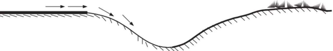
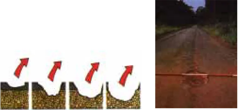
In hilly and mountainous terrain, efforts will always have to be made to reduce the flow velocities in the drains and in the outlets (Fig: 8).
The best preventive maintenance for roads is to maintain road drainage. This makes the road last longer. DRAINAGE FEATURES
Maintenance of Road Drainage | 21
3.2 Objectives of Road Drainage and the Maintenance Task
The objectives of road drainage can be broadly classified as:
• Prevention of accumulated surface water on or by the roadway and flowing onto the roadway. • Interception of ground water from entering the road structure from beneath.
• Prevention of erosion of the roadway edges, drains, embankment slopes, cut slopes and the roadside itself. • Conveying river and stream water across the roadway in an appropriate manner.
The objective of road drainage maintenance is to ensure that its route is free from obstruction and to retain the cross-section and the gradient. They must function properly so that surface water and ground water can drain freely and quickly away from the road.
“Water is the worst enemy” of any road.
It can:
1. Erode soil.
2. Weaken pavement.
3. Destroy shoulders and slopes. 4. Wash out culverts and embankments.
Regular site inspections, particularly during the rainy season will be an essential tool to clearly identify the problems.
3.3 Drainage of Road Surface
Drainage of road surface is affected by the following aspects: • Cross-falls
• Surface conditions • Shoulder level • Scupper drains
Cross-Fall
Road surface should be constructed and maintained with sufficient cross-fall to shed the stormwater to the edges and into the side drains. For this purpose the following cross-falls are normally adopted.
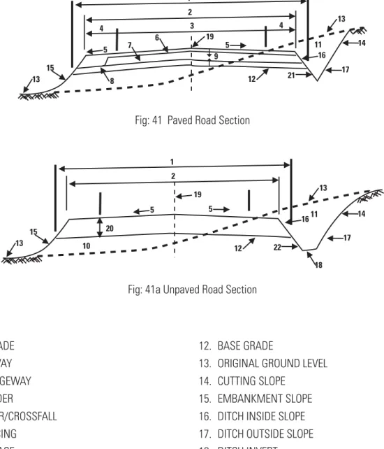
Paved roads - 2 to 3 per cent Earth and gravel roads - 4 to 6 per cent
Shoulders - desirable maximum of 6 per cent
Normally, the shoulder should possess a greater cross-fall than the road.
A
B C Cross-fall (percentage) = AB X 100
BC
Eg: If AB is 15 cm and BC is 3.0 m (300 cm) the cross fall is 5% 15 x 100 = 5%
300
Surface Conditions
Surfaces of roads should always be devoid of potholes, ruts, depressions and cracks as far as practicable, as these will allow water to penetrate into the road structure and cause damage.
Shoulder Level
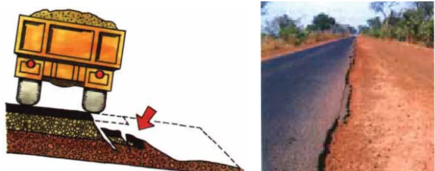
It is a common occurrence that the edges of paved roads are eroded due to the action of water. This is particularly so where the water tends to run along the road as a result of road gradients being relatively high or as a result of insufficient cross-fall, with water being unable to crossover as indicated in Fig: 9.
Fig 9: Eroded edge of carriageway
A shoulder being higher than the carriageway is a common occurrence with most of our roads. Reducing such high shoulders is costly so finding alternative ways of dealing with the water is important for ensuring long road life.
Scupper Drains
Scupper drains provide a relatively cheap means of draining across shoulders that are high. These are shallow transverse drains cut to taper from the road edge to the side drains, to average widths varying from about 0.6m to about 1.0m and to depths to suit the shoulder and the drain. They may be suitably angled to assist the flow as shown in Fig: 10. Their gradients should be kept to between 4 and 6 percent, generally. Where scupper drains lead water over embankments or hillsides, suitable drop structures will have to be constructed to ensure that such water does not cause erosion. Scupper drains should be spaced at suitable intervals normally varying between15 - 30m and as far as practicable, they should be positioned at the lowest point within each interval.
Fig: 10 Scupper drains
Another common problem in Sri Lanka is where the shoulder gets eroded from cars using the unpaved shoulder when meeting a large vehicle coming the opposite way, or when multiple vehicles are using a single lane. This causes a small depression at the edge of the road that collects water when it rains and does not allow the water to flow to the roadside ditch.
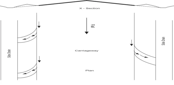
Side Drains of Roads
The essential function of side drains is to collect water from the roadway, to intercept outside water from flowing into the road and convey the water to a suitable outlet point. The outlet point could be lead-away drains or natural streams.
Sid e D rain Sid e D rain X - Section Fa ll Carriageway Plan
Maintenance of Road Drainage | 23
Shape and Size of Side Drains
Normally, the side drains should have a trapezoidal shape with side slopes not less than 1:1 and bottom widths not less than about 0.45m so that the sides are stable and self-cleaning and de-silting. The depths of these drains should be a desirable minimum of 0.6 m
Fig: 12
Normal Side Drains
Fig: 13
However, where it is necessary to keep the ground water low, the depths have to be increased to over 1.0m.
In restricted areas both the side slopes and the bottom widths may be reduced. However, cutting the sides vertically should normally be avoided.
The bottom and the further side of the drain should be manually shaped as shown. However, finishing the drains to a V shape should only be resorted to in places where there are space restrictions.
Slope 1:1
Slope 1:1
b
Desirable minimum values
d = 0.6m
Angle Drain
Fig: 14
Saucer Drain
Fig: 15
Drainage Ditches
In low lying areas and in restricted areas where drains cannot be continued due to obstructions such as parapet walls, electric posts etc., it is suggested to have closed end ditches (Absorption Ponds).
Lead-Away Drain
Fig: 16 Lead-Away Drain
Catch drain
Cutting
Catch drain
Embankment
Drainage is not possible without lead-away drains. Lead-away drains are essential to take away and dispose of the water from side drains. It is very important for the engineer to check the lead-away drains regularly to avoid blocks, which will subsequently cause the failure of drainage.
The lead-away drains, particularly in the hill country, should be protected from erosion due to fast flow of stormwater. Suitable drop structures and stilling basins may have to be constructed, in this regard. Lead-away drains in lower lying areas on the other hand, have to be de-silted regularly due to the slowness of flow of stormwater in them causing deposition of silt.
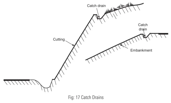
Catch Drains (Interceptor Drains)
The function of a catch drain is to intercept surface water flowing towards a road cutting or formation embankment. It thus prevents the water flowing down the cut batter, which may cause severe scouring.
Fig: 17 Catch Drains
Batter Drains
In a situation where water has to be drained down an embankment slope or down a cutting batter, batter drains are constructed. Normally, the slope of the drain down the batter is too steep to allow the water to flow. As such, batter drains are generally lined with concrete or grouted stone. The batter drains may also be stepped to break the flow of water.
Subsurface Drains/Sub Soil Drains/Under Drains
Subsurface drains are provided to lower the water table, particularly due to the water trapped by impervious material. An under drain normally consists of perforated pipes surrounded by an aggregate fill. Pipes used may be of concrete, clay or PVC.
3.4 Maintenance Methods – Roadside Areas
Including the shoulders and side slopes, most roadside area maintenance activities can be achieved by labour, and are suitable work for a mobile or local gang, or an individual lengthman living close to the road.
1. Shoulders
a. Defect: Obstructions such as rocks, trees or tree branches, soil heaps and abandoned vehicles/debris.
Main Causes
• Material fallen from slopes or trees, material washed onto the shoulders. • Debris left by road users.
If Neglected
• Hazard to road users.
• Obstruction of water flow from carriageway. Remedies
• Remove obstructions.
b. Defect: Shoulder Higher than Carriageway
Main Causes
• Carriageway surface material has collected on the shoulder by the action of traffic/water. • Soil from the cutting has slipped onto the shoulder.
• Vegetation has trapped material on the shoulder.
• Shoulder material has been displaced by the action of traffic. If Neglected
• Surface water can pond at the edge of the carriageway and weaken the pavement and shoulder. • Danger of accidents.
• Excess material may block the roadside ditch. Remedies
• Reshape or re-grade shoulder surface to the correct level. • Vegetation control.
Maintenance of Road Drainage | 27
c. Defect: Shoulder Lower than Carriageway
d. Defect: Ruts or Depressions
Main Causes
• Traffic has been travelling on the shoulder and material has been worn away.
• Water erosion of the shoulder, settlement of the shoulder, the carriageway has been overlaid leaving the shoulder surface lower than the pavement.
If neglected
• Inadequate support for the road pavement.
• Water collects and softens the shoulder and pavement foundation.
• The edge of the pavement will break when vehicle wheels run over it, increasing the risk of accidents.
e. Defect: High Vegetation on Shoulders
Main Causes
Grass, weeds, bushes or trees have been allowed to grow unchecked. If neglected
• Surface water can pond at the edge of the carriageway and weaken the pavement.
• Silt accumulates at the edge of the carriageway, the visibility for road users is reduced, with increased risk of accidents with persons or animals.
• Increased fire hazard in the dry season. Remedies
• Vegetation control.
Fig: 19
Fig: 20
2. Drains
a. Defect: Obstructions
Main Causes
• Vegetation growth, bushes, fallen trees, debris, loose silt, loose rocks. If neglected
• Blockage of ditch. Remedies
• Clearing and cleaning.
b. Defect: Silting
Main Causes
• Invert slope is too flat; the water cannot flow at sufficient speed. If neglected
• Ditch blockage. Remedies
• Deepen ditch (de-silting), and/or provide new turnouts.
• Where deepening or turnouts are not possible because of topography, the construction of a new culvert with a drop-inlet may be possible, in order to discharge water onto the other side of the road.
c. Defect: Ponding in Drains and on Shoulders
Main Causes
• The ditch cross-section is too small; the ditch gradient is too flat. If neglected
• The shoulder material becomes soft and can easily erode. • The pavement can also be flooded and thereby weakened. Remedies
• Deepen ditch. • Provide new turnout.
d. Defect: Drain Cross-Section Destroyed (Unlined Drain)
Main Causes
• Vehicular or animal traffic; cave-in. If neglected
• Partial silting will result if the ditch sides have collapsed. • Erosion can start where water flow passes the blocked section.
Remedies
• Reshape/re-grade ditch, line drain.
e. Defect: Invert and Sides of Drains are Eroded
Main Causes
• Invert slope is too steep. If neglected
• The water flows at high speed and starts eroding the soil. The ditch becomes deeper (ravine). The sides then cave-in, the road shoulder and even part of the carriageway can be washed away.
Remedies Erosion control:
• Re-grade/realign drains. • Provide repair scour protection. • Line drain slopes and invert. • Construct cascade.
f. Defect: Drain Lining is Damaged
Main Causes
• Poor construction workmanship.
• Soil settlement, erosion of soil under ditch lining. • Poor alignment or sudden change in flow direction. If neglected
• When flowing water reaches the soil protected by the lining, erosion starts.
• The amount of soil washed away increases; the lining is further damaged by loss of support, leading to complete destruction of the lining.
Remedies Erosion control: • Repair lining. • Realign drain.
g. Defect at Drain Outfall
Main Causes • Flow too fast.
• Flow too concentrated for the soil at the outfall to resist. If neglected
• The erosion may eventually threaten the road as well as the surrounding land. Remedies
Reduce water flow and speed: • Realign drain to flatter gradient.
• Provide new turnout drain, upstream from existing. Reduce impact at outfall:
• Construct cascade. • Construct flow spreader. Erosion control for the soil: • Turfing.
• Wattling. • Stone pitching.
3. Manholes and Drainage Pipes
a. Defect: Water Overflowing at Manhole
Main Causes
• The manhole or connected underground pipes are blocked and water cannot flow as intended. If neglected
• Flooding of road shoulder or carriageway. • Drainage system becomes ineffective.
• Danger of earth slip or weakening of the pavement. Remedies
• Clear manhole and underground pipes.
b. Defect: Manhole Cover or Grating is Missing/Damaged
Main Causes
• Accident, vandalism.
Maintenance of Road Drainage | 31
If neglected
• Open manholes become a danger to people and animals. Vegetation and debris have uncontrolled access and blockage can occur.
Remedies
• Replace manhole cover or grating.
c. Defect: Manhole is Covered with Soil and Vegetation
Main Causes
• Silting of the ground area at manhole; manhole cover level possibly set too low. If neglected
• Possible blockage of the drainage system at the manhole, due to an undetected accumulation of silt in the manhole. Remedies
• Clear manhole area. Public require education on:
• Not burning trash in drainage ways.
• Collecting leaves and other debris in drainage ways. • Cleaning of drainage ways.
4. Maintenance of Culverts and Bridges
a. Defect: Silting or Debris Blocking
Main Causes
• Invert slope too flat.
• Culvert constructed too low, so that material from the stream bed becomes deposited in the culvert. • Vegetation and floating debris carried by water has become lodged in the culvert.
If neglected
• The intended waterway opening will be reduced so that floodwater cannot flow. It will back-up or pond on the Fig: 23
upstream side of the culvert and may eventually overflow the road embankment. The road is then in danger of being washed away.
Remedies
• Clearing and cleaning.
• If floating debris is a problem, the provision of a debris rack should be considered.
b. Defect: Cracks
Main Causes
• Settlement of soil below culvert. If neglected
• Minor damage: If the settlement is minor, only light cracking will result in headwalls, wing walls and the main structure. This will hardly affect the functioning of the structure.
• Major damage: If the settlement is severe, it will cause large relative movement of culvert pipes so that embankment soil will enter through the cracks and block the culvert, or the culvert may collapse. The culvert must then be reconstructed.
Remedies • Repair cracks.
• Reconstruct at correct level and fall.
c. Defect: Erosion of Culvert Bed at Outlet
Main Causes
• The culvert invert has been constructed too steep so that the water flows too fast.
• The culvert invert has been constructed too flat with an excessive drop at the outfall (these are design or construction faults).
If neglected
• The streambed is washed. The culvert downstream head and wingwalls and even a section of the culvert and road embankment can collapse.
Remedies • Erosion repair.
• Construct outfall basin.
d. Defect: Minor Headwall Damage
Main Causes • Minor settlement. • Scour or erosion. If neglected
• Erosion at the headwall. • Culvert blockage or collapse. Remedies
• Headwall repair.
Side drains
Carriageway
Shoulder
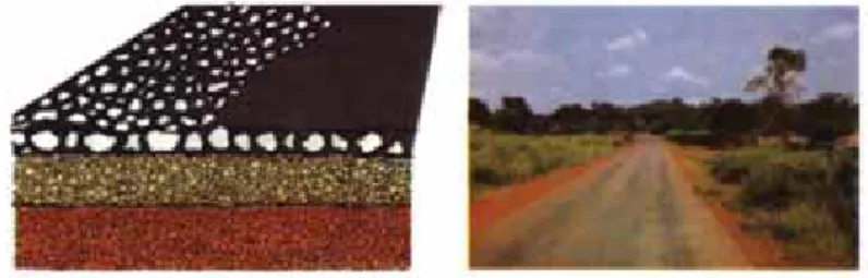
SESSION 4:
MAINTENANCE OF UNPAVED ROADS
Unpaved Road
4.1 Grading / Dragging
The task is to improve earth and gravel roads by Grading/Dragging the existing surface material. Grading is normally a ROUTINE MAINTENANCE task. It is carried out by a self-propelled grader.
Dragging can be done with the help of a dragger. Objective
• To restore the 'camber' by grading the sides and shoulders towards the centre of the road. Grading is used to correct the following defects:
Defects • Loss of shape • Ruts • Potholes • Corrugations • Erosion gullies
• Silted or blocked ditches
Resources
Personnel, plant and tools, signs and safety equipment. Grading is a fast moving activity.
The grading requirements depend on: • Road condition (light or heavy grading). • Moisture conditions.
• Compaction requirements. • Resources available.
Personnel
The categories and numbers of personnel depend on the equipment resources used. Each grading gang should include: • Supervisors
Plant Operators and Drivers
• 1 operator for each motor grader. • 1 driver for each tractor.
• 1 light vehicle driver.
• 1 operator for each motorised roller. • 1 driver for each water tanker.
Maintenance of Unpaved Roads | 35
Workforce
• 1 mechanic for daily servicing and minor repairs.
Plant and Tools
Motor Graders
Motor graders of 100 hp (75 kW) or more can be used for light or heavy grading. Rollers
1 or 2 rollers, if available. Rubber tyre (Pneumatic) rollers are preferred. They can be self-propelled. • Water
When water tankers are needed and available, the number required will depend on the distance that water has to be hauled. These should be fitted with a spray bar.
• Water Pump
A separate water pump will be needed if none are fitted to the water tankers. The pump should be of sufficient capacity to fill the tankers quickly.
• Other Vehicles
Transport for the supervisor. • Tools
• Camber board made as shown from 20 mm treated plywood or hardwood to give the required slope e.g. 1 in 20 (5%) slope.
A selection of hand tools, as required.
Signs and Safety Equipment
The following items should be used where possible. • Traffic Signs
■ 2 'Men Working' signs. ■ 2 'End of Restriction' signs.
These should be clean and in good condition. • Clothing
The workers should wear yellow or orange coloured safety vests. • Lights
The grading equipment should work with headlights switched on and, where possible, yellow flashing warning lights. • Flags
If yellow flashing warning lights are not available, vehicles and equipment should carry a red/yellow flag.
Important Rules
Do not make a final pass down the centre of the road with the grader blade horizontal. This flattens the centre of the road and causes water to pond leading to rapid deterioration of the surface.
Do not leave a windrow on the road overnight as this is a danger to traffic.
Compaction
When a compaction plant is being used, it must follow the grader only on sections where grading has been completed. About 8 to 12 passes of a roller, depending on the type of gravel, will be needed to achieve full compaction. Work from the edge to the centre of the road.
• Shoulders are treated as part of the running surface.
• Junctions and bends - graders must not stop near junctions or bends where they will be a danger to traffic. • Check the camber.
Maintenance of Unpaved Roads | 37
Camber Board
Camber should be checked with a camber board at about 100 metre intervals along the road. To use the camber board, place it on its edge across the road with the shorter end pointing towards the centre line.
Check the 'level bubble'. If it is centred, the camber is correct. If it is not centred, the camber is either too steep or too flat and further grading and compaction are required.
Super Elevation
On bends, the surface must be straight (at 4-6%) from shoulder to shoulder with the outer shoulder higher. Any crown on a bend can be very dangerous to traffic.
The super elevation must be retained for the complete length of the bend. On the transition at each end of the bend into the straight sections, the super elevation should be gradually reduced.
The shape of the road must be maintained over culverts to avoid a hump. Material should be brought in if necessary from either side of the culvert to maintain a cover to the top of the culvert.
Bridge decks should be kept free from gravel. Loose material should be swept away. It is important to have smooth approaches to the bridge. They should be smoothed out using the back of the blade with the grader working in reverse.
Fig: 28
Grading Ditches and Drains
Before the road surface is graded, the side ditches must be cleaned.
Narrow flat-bottomed ditches are not well suited to maintenance by grader. These are best cleaned out by hand. Graders should be used to maintain V-shaped ditches and wide flat-bottomed ditches.
Material from the ditch should not normally be graded onto the running surface.
• The first pass cleans the side slope near the road and windrows the material to the bottom of the ditch. • On wide flat-bottomed ditches, the second pass cleans the ditch bottom.
• The next pass cleans the ditch back slope and removes the material to the top of the ditch.
• If possible, a third pass is used to push the material away from the edge of the ditch, to prevent it washing back.
stra ight curve 1 2 3 3 2 1
Maintenance of Unpaved Roads | 39
Fig: 30
4.2 Labour-Based Reshaping
The task is to restore the shape (reshaping) of earth and gravel roads by Labour-Based Methods. The task and objects are the same as that of equipment intensive methods.
Defects
Defects are the same as that of equipment intensive methods.
Resources
Personnel
• 1 Supervisor visiting regularly. Workforce
• 1 or 2 overseers for each section of road.
Plant and Tools
• 1 pickaxe. • 1 shovel. • 1 mammoty. • 1 rake.
• 1 hand rammer with metal shoe. • 1 wheelbarrow.
• 1 ditch and slope template and spirit level. • 1 camber board and spirit level.
Signs and Safety Equipment
On low volume roads the following should be provided: • Traffic Signs
■ 2 'Men Working' signs.
■ 2 yellow/orange flags to be placed on the road shoulder. • Clothing
■ Yellow or orange coloured safety vest to be worn by the workers.
Execution of Work
The Supervisor transports the tools and safety items to the site using the wheelbarrow. The warning signs or flags are placed either side of the worksite. The workmen or lengthman trims the surfacing material with the pickaxe, hoe or mammoty and rakes it to form the required camber and crossfall. The shape is checked with the camber board and spirit level. If gravel stockpiles are provided, any local depressions are filled with material transported in the wheelbarrow. The loose material is compacted with the hand rammer.
Personnel Supervisors • 1 Overseer.
• 1 headman for each 10 to 20 workmen (usually from the local workforce). Workforce
• 20 to 40 workmen. Support (as necessary) • Water carriers. • Storeman. • Watchmen.
• Hand tool sharpening and repairs.
Maintenance of Unpaved Roads | 41
Major Reshaping Plant and Tools
Approximate requirements, actual number will depend on conditions. • 1 pickaxe for every 10 workmen
• 1 hoe for every 2 workmen • 1 mattock for every 10 workmen • 1 shovel for every 2 workmen • 1 rake for every 5 workmen
• 1 hand rammer for every 10 workmen • 1 wheelbarrow for every 10 workmen • 1 bush knife for every 10 workmen • 2 crowbars
• 4 files (for sharpening tools)
• Axe
• Saw
• Grass Slasher
• 10 ranging rods and adjustable profiles • 1 tape measure (30 metre)
• 1 camber board and spirit level • 1 ditch and slope template • 2 mason's hammers • Wooden pegs
• Balls of string/sisal twine
• If available, a hand or animal drawn roller
4.3 Patching
Maintenance of Unpaved Roads | 43
Fig. 34
Patching is sometimes required between grading and reshaping operations, or before grading when the potholes or depressions are large. Patching may either be used to repair worn or eroded areas or can be used to restore areas, which become soft when it rains. This maintenance activity consists of replacing or adding new gravel surfacing material over relatively small areas. Patching may be carried out by a mobile gang or by labour based methods. Patching is normally used to refer to resurfacing work involving less than 1 or 2 truck or trailer loads of material per day.
Defects
Patching is used to correct:
■ Potholes
■ Ruts
■ Soft Spots ■ Erosion Gullies
Where there are a large numbers of potholes, the section will need scarifying with a self propelled grader.
Re-Gravelling
Personnel • Supervisors • Charge hands
• Plant Operators and Drivers • 1 Driver
Workforce
• 2 to 6 labourers • 2 Traffic Controllers Plant and Tools
• Vehicles • 1 small truck OR
• 1 tractor and trailer(s). If two trailers are available, one trailer can be loaded while the other is hauled to the worksite.
Compactors
• 1 hand controlled vibrating roller and fuel OR
• 1 hand rammer with metal shoe for each labourer used on compaction work Fig. 36
Maintenance of Unpaved Roads | 45
Tools
• 1 broom for every two labourers • 1 pickaxe for every two labourers • 1 shovel for every two labourers • 1 mammoty for every two labourers • 1 rake for every two labourers • 1 wheelbarrow
• 1 hand rammer with metal shoe for each labourer used on compaction work (if no vibrating roller is available) • 1 drum for water (200 litre)
• 1 bucket or watering can Materials
• The gravel must be at least as good a quality as the material already surfacing the road. Its use must be approved by the Maintenance Engineer.
Water
• A container will be required.
Signs and Safety Equipment
The following items should be provided where possible. Traffic Signs
• Reversible 'Stop/Go' signs • 2 'Speed Limit' signs (50 km/hr) • 2 'Men Working' signs
• 1 'Road Narrows From Right' sign • 1 'Road Narrows From Left' sign • 'End of Restriction' signs Barriers
• Lane closure barriers Traffic Cones
• As many as required; at least 10 will usually be required. Clothing
• Yellow or orange coloured safety vests or safety harnesses to be worn by the Supervisor and all the work force. Vehicles
• All vehicles and equipment should work with headlights switched on and, where possible, should carry yellow flashing warning lights.
Flags
Finally, the patched area is filled evenly with the gravel to approximately 3 centimetres above the level of the surface and is spread and raked to the correct shape. 3 centimetres is approximately the thickness of a rake handle. The patch is then compacted using the roller or hand rammer to give a surface, which is slightly above the level of the surrounding road. Both large and small areas to be patched are repaired in the same way; the rammer is used for the smaller potholes. The roller is used for larger areas; the hand rammers will still be required for the corners and short edges.
4.4 Re-Gravelling (Labour and Tractors)
This is the most commonly used technique for the re-gravelling of running surface. Haulage is carried out by agricultural tractors of 45 hp (34kW) or greater, and gravel trailers. Tractor drawn rollers provide compaction. This method is usually appropriate for gravel hauls up to about 10 km. For haulage distances greater than 10 km, trucks are usually more economical. However, these may be loaded manually.
The surfacing material of unpaved roads is worn away by traffic, eroded by rain and blown away as dust. Before all the gravel surfacing has worn away, the road requires re-gravelling. Re-gravelling is normally a periodic maintenance task. It is important that the Maintenance Officer plans re-gravelling work well in advance so that work is carried out before serious defects appear. Before re-gravelling is carried out, it is important to make any necessary repairs or improvements to the camber and drainage system of the road. If this is not done, the new gravel surface will deteriorate very quickly. Re-gravelling is normally carried out with one layer of 15 cm thickness. Usually a continuous layer of gravel is laid on the existing running surface, however, on some occasions short stretches showing severe defects are covered under a spot re-gravelling operation.
Re-gravelling is used to correct • Loss of surfacing material
Defects
Re-gravelling is needed before the subgrade is exposed on the road surface. Re-gravelling is also used to correct • Loss of shape
• Ruts • Potholes • Erosion Gullies
Maintenance of Unpaved Roads | 47
Resources Personnel • Supervisors.
• 1 overseer at the quarry. • 1 overseer at the road site. Plant Operators and Drivers • 1 driver for each tractor. Workforce
• Depending on the number of tractors and haul distance. • Mechanics for daily servicing and repair.
• Water carriers. • Storeman. • Watchmen.
• Hand tool sharpening and repairs. Plant and Tools
• Tractors. The number of tractors required will depend on the gravel haul distance and plant availability. • Additional tractors may be required for hauling rollers.
• Water and fuel. Trailers
• 2 trailers per tractor if possible. This allows one trailer to be filled while the other is hauled to the road site. 33 metre capacity trailers are most suitable for 45 to 75 hp (34 to 56 kW) tractors.
Other Items
• 1 towed deadweight roller or hand operated vibrating roller. • 1 towed water bowser.
• 1 towed fuel bowser.
• Light vehicles for the transport of the two supervisors.
Tools - typical hand tool requirements for a workforce of up to 100 labourers. • 70 shovels • 20 hoes • 50 mammoties • 50 pickaxes • 10 bush knives • 5 wheelbarrows • 8 crowbars • 20 rakes • 4 sledgehammers
• 2 tape measures (30 m) • 10 buckets
• 5 water containers
• 1 camber board and spirit level • 2 mason's hammers
• wooden pegs
• balls of string/sisal twine • 4 fifes (for sharpening tools)
Materials
Gravel obtained from a quarry or gravel pit must be of a quality that meets the specifications. Support and Safety Arrangements
Arrangements should be made, as necessary, for the following: a) Recruitment of workmen.
b) Setting up temporary site camps.
c) Facilities, secure hand tool storage, water supply. Signs and Safety Equipment
As in the previous case.
Before starting the job, a check should be made to ensure that everything is arranged as necessary. Identify gravel source, test material and make any acquisition arrangements. Arrangements must be made for refuelling on site. Temporary Signposting
As in the previous case.
Execution of the Work
The following steps are normally required: • Daily planning.
• Preparation of road surface. • Preparation of quarry access road. • Gravel excavation and stockpiling. • Loading.
• Hauling.
• Offloading and spreading. • Compaction.
• Stockpiling gravel for routine maintenance.
When using a large labour force, it is essential to break the work down into simple manageable operations to achieve satisfactory productivity.
Daily Planning
The deployment of tractors and trailers and the number of labourers for each activity depend on: • Quantity of gravel already stockpiled.
• The haul distance.
• Number of serviceable tractors and trailers. • Tractor power.
• Haul route condition.
The plans for each day should be prepared at the end of the preceding day's work. Tasks should be set based on local experience.
Site Preparation
Wherever possible, before the re-gravelling work starts, a diversion if necessary should be arranged.
Preparation of Surface
After signs have been placed, the existing surface should be reshaped to the correct camber as described. If possible, the reshaped surface should be compacted. The camber should be checked with a camber board. The drainage system should be checked and repaired if necessary.
Preparation of Quarry and Access
Plan the quarry excavations and stockpiles so that: the quarry can be fully exploited; the overburden is stockpiled so that it will not hinder future extension and that it can be used to reinstate the quarry. Gravel quality may vary within the quarry. Environmental damage by poor drainage and erosion should be minimised. Allow the tractors and trailers to enter and leave without obstructions.
Repair the quarry access road, if necessary. Gravel should be excavated and stockpiled at least one day before. In addition, it should be excavated and stockpiled alongside to allow easy loading. In hillside quarries, excavate material to ease loading and ensure safety of workmen. Workmen must have enough room to work safely and comfortably.
Loading
Where possible, trailers should be parked at the same height as, or preferably below stockpiles for ease of loading. The loading gang should be divided into groups of 4 to 6 workmen.