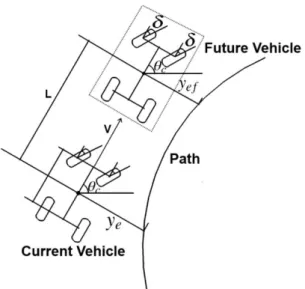
A Path Tracking Algorithm Using Future Prediction Control with Spike Detection for an Autonomous Vehicle Robot
Full text
Figure


Related documents
• Intelligent Robotics, Artificial Intelligence, Multi-Agent Systems, Coordination, Intelligent Simulation, Serious Games, Information Systems, Robotic Soccer, Constraint
The second and third factors cited by the trial court were that Defendants received actual notice of the lawsuit, and that Plaintiff complied with Tenn. Although Plaintiff
Fidelity to core program scope & sequence Use of additional materials to core program Instructional grouping Setting instructional purpose Assessments (on- going,
1.) Shearlets Registration (on Original or on Compressed Image) => Get Initial Guess. 2.) Wavelets Registration Using Initial Guess from (1) => Get Final
he Active Living Center at the Andover/North Andover YMCA is a great resource for older adults in our community in a dedicated space provided through a generous donation from
In South Africa, the appropriate age for primary education is 7–13 years, but some of the 13- year olds may be enroled beyond primary (in secondary school) and other older children may
The spectrum obtained from a suspect compound should visually match the spectrum obtained from a contemporaneous standard. Since full scan data may include
2.10 presents the induction machine model in synchronous reference frame linked to the stator flux, with inputs stator voltages and currents, and load torque.. Block diagram

