S
S
e
e
c
c
I
I
E
E
H
H
a
a
n
n
d
d
b
b
o
o
o
o
k
k
o
o
f
f
N
N
e
e
t
t
w
w
o
o
r
r
k
k
S
S
e
e
c
c
u
u
r
r
i
i
t
t
y
y
The SecIE Handbook for Network Security Version 1.0 - Mannheim, 10. April 2007 © SecIE e.V.
Publisher:
SecIE - Security and Administration in Industrial Ethernet e.V. c.o. IAF Universitätsplatz 2 39108 Magdeburg Germany mail : [email protected] web : www.secie.org Editors:
Dipl. Ing. Matthias Dehof Marcus Tangermann Dr.-Ing. habil. Arndt Lüder
Otto-von-Guericke Universität Magdeburg Center Verteilte Systeme
Universitätsplatz 2 39106 Magdeburg Germany
www.uni-magdeburg.de/iaf/cvs
Recipients of this document are invited to submit, with their comments, notification of any relevant patent rights of which they are aware and to provide supporting documentation. The following parties have contributed to this document:
DEHOF ingenieur + technik Matthias Dehof Data Systems Detlef Kilian HIMA
Paul Hildebrandt Gmbh + Co KG
Stefan Ditting
Dr. Arndt Lüder Nortel Networks Germany GmbH & Co. KG Andreas Herden
PerFact Robert RAe
Weidmüller Interface GmbH & Co. KG Dr. Kai Lorentz Hirschmann Automation and Control GmbH Ralf Kaptur GIP – Engineering AG Wilfried Gentner Netways GmbH Michael Kern
All illustrations, charts and layout examples shown in this document are intended solely for purposes of example. SecIE assumes no responsibility or liability (including intellectual property liability) for actual use based upon examples given in this publication.
Reproduction of the contents of this copyrighted publication, in whole or in part, without written permission of SecIE is prohibited.
Contents
1 Introduction... 5
2 Basics for Industrial Ethernet Security ... 7
2.1 What is Security? ... 7
2.2 Security Classification ... 9
2.2.1 Security Classification Example - Light Bulb Factory... 10
2.2.2 Security Classification Example - Automotive parts... 10
2.2.3 Security Classification Example – Pharmaceutical process... 11
2.3 The IP protocol family ... 11
2.3.1 Design of the IP family ... 11
2.3.2 Security Problems of IP ... 13
2.4 Communication relations in an enterprise network ... 14
2.5 Network architecture for Industrial Ethernet ... 16
2.6 Defense strategy ... 18 2.6.1 Hard-perimeter... 18 2.6.2 Defense-in-depth ... 19 2.7 Security Components ... 20 2.7.1 Packet Filter... 20 2.7.2 Application Gateway ... 22 2.7.3 Demilitarized Zone (DMZ)... 23 2.7.4 Switches ... 23 2.7.5 Router 23 2.8 Differences between Office and Automation Networks ... 24
3 SecIE Security Methodology ... 27
3.1 Security demand classification ... 28
3.2 Communication relations... 29
3.3 Defense Strategy ... 31
3.4 Defense Structures ... 31
3.5 Devices / Protocols ... 33
3.6 Defense measures ... 34
4 The Security Cookbook... 37
4.1 Remote Access ... 37
4.1.1 Terminal Server ... 37
4.1.2 Network Manager ... 38
4.2 Distributed Web-Server Access (VPI) ... 39
4.3 VPN based approach and Security Portals ... 40
5 SecIE Security Data Sheet ... 41
5.1 How to fill out the SDS ... 41
5.1.1 General ... 41
5.1.2 Page 1 - General ... 42
5.1.3 Page 2 - Network Ports and Services ... 42
5.1.4 Naming Conventions ... 43
5.2 Security Data Sheet Creator (SDS-C)... 43
7 Annex: Security Data Sheet Template ... 45
8 Annex: Security Data Sheet XML Schema ... 47
9 Annex: Network Services... 49
9.1 ICMP ...52 9.2 ARP 53 9.3 DHCP ... 54 9.4 DNS... 55 9.5 FTP 56 9.6 TFTP ...57 9.7 Telnet ... 58 9.8 SMTP ... 59 9.9 59 9.10 SSH 60 9.11 SNMP ... 61 9.12 HTTP ...62 9.13 DynDNS ... 63 9.14 Modbus-TCP ... 64 9.15 EtherNet/IP... 65 9.16 EtherCAT ... 66 9.17 ETHERNET Powerlink ... 67 9.18 RPC / DCOM... 68 9.19 LDAP ...69 9.20 Kerberos... 70 9.21 IPSEC ... 71 9.22 PPTP ...72 9.23 L2TP / IPsec... 73 9.24 SOAP ... 74
9.25 Remote control software ... 75
9.26 NDDS ... 76
9.27 MAP/MMS ... 77
9.28 RADIUS... 78
1 Introduction
Ethernet based communication systems have entered the factory floor. During the last 5 years different fields of application using different Ethernet based communication protocols and technologies have been established ranging from web based management of devices to motion control applications.
This increasing use of Ethernet based services and devices came for many companies through the backdoor: first a simple FTP session for firmware uploads and a telnet session for changing settings, then a web server for advanced and comfortable configuration and diagnostics, and finally the use of real-time Ethernet communication protocols for device communication within control applications. It was a small step from using these devices point-to-point connected to a serviceman's laptop to connecting the devices to a company network. With the broad use of PC based devices, it was possible to connect anything and for quite a time, finally, the network was just what is was made for.
But with the increasing use of Ethernet based communication technologies also the problems of this technology have entered the factory network. The possible data exchange using eMails or direct device access will enable an undue influence on the devices by hackers, with-collar criminals, or even unilluminated employees.
When more people were accessing the network - and an increasing number of non-technicians and non-employees were among them - the network was opened to the Internet and was used for web-access and eMail services. Thereby, viruses and worms coming with laptops and eMails, some of them do no harm but others may cause the loss of a complete production line. Even when these viruses have no direct effect on devices, overloaded network traffic is even worse than a single deleted hard disk.
The direct access to control devices using HTTP or SNMP based device management systems will, in principle, enable unauthorized people to acquire control system and production system sensitive data and to change sensitive system settings causing economic disadvantages.
As a matter of fact, the IT departments are confronted with a complete new line of problems. Any intrusion, by accident or intention has a bigger effect than in the office world.
An automation network needs to be fail-safe. Data within an automation system need to be protected from unauthorized access. The unauthorized change of control relevant data or even the circumvention of a data exchange may result in a production system break down. A down time of a production line of a few minutes can cost some thousands of Euros because it may take some hours to restart the complete line. In contrast to this a short breakdown in the office environment is equally disturbing, but the consequences are different.
To cope with the mentioned problems and to ensure the security of industrial communication systems special technologies and strategies have been developed or even from the office world adapted to the factory floor. One important role within this process has been played by the SecIE Joint Technical Working Group (JTWG) “Network Security”. Within this JTWG the state of the art of network security technologies for industrial application have been collected and aggregated to an advice for best practice.
Based on the results of the SecIE TWG “Network Security” the Handbook of Network Security has been created. It will be maintained by the members of the JTWG and reflects the current status of technology. The Handbook is not a static book, but subject to change to keep up with threats and developments.
The Handbook was designed to
establish "know-how" for network security in industrial applications and make this accessible for to users
give recommendations on how to plan secure networks
provide tools for network analysis and escalation schemes
create guideline for network security to be provided to IT and factory floor personnel
give input to normative committees, such as IEC The user's benefits are
support for security risk analysis,
support in the selection of appropriate security measures and
most important - the avoidance of production down time caused by security leaks. All-in-all, the SecIE Handbook of Network Security will provide interested people with the necessary knowledge about existing security problems, useable security architectures, and all necessary activities to establish these architectures.
To follow this aims the handbook is organized as follows.
Within the following (the second) chapter necessary basics about network security will be described. This includes a definition of the term “Security”, the term of SecIE Security Classes, the description of basic protocols, structures, and architectures and its security problems, defense strategies, and security components with its security relevant behavior.
The third chapter will describe in detail the security methodology developed by SecIE TWG “Network Security” with strategies, structures, devices, protocols, and defense measures.
Chapter four can be seen as a cookbook for network security providing best practice scenarios for special application cases.
Chapter five introduces the SecIE Security Data Sheet, a mean for collection and distribution of security relevant information of devices, systems, and networks based on the SecIE Security Methodology. Within this chapter the SecIE Security Data Sheet will be described in detail and its application and benefits in practice will be considered.
The handbook will conclude with three annexes. The first annex will provide a template of the SecIE Security Data Sheet and the second one will give the XML schema used for the computer based processing of the SecIE Security Data Sheet. The third annex will provide a detailed listing and description of 28 Ethernet based communication protocols used within factory communication systems including a security relevant survey of each protocol.
2 Basics for Industrial Ethernet Security
The aim of the following section is the provision of basic information about network security problems and its avoidance or protection. Therefore, some basics for Industrial Ethernet Security will be given.
First of all, the term “Security” is defined and different security objectives are introduced. Based on this definition a classification of security levels is introduced.
To ensure the understandability of the majority of security relevant problems within this chapter three main communication system relevant topics will be picked up. At first the IP protocol and its application and security relevant problems within Ethernet based communication systems will be considered, at second different communication scenarios used in practice will be observed in a generic way, and at third usually used network structures will be sketched.
Based on this set of prerequisites existing network security approaches and devices usable within them will be analyzed. The main interest here is placed on the hard-perimeter approach and the defense-in-depth approach as the two important security architectures and on the mainly used security architecture components Packet Filter, Application Gateway, and Demilitarized Zone.
2.1 What is Security?
A very important issue for further discussions is a clear definition of what "Security" means.
In contrast to "Safety" which concerns operators, users and the general public, "Security" addresses the prevention of illegal access - in the widest sense - to the automation system. Security thus has implications for safety as well.
In this handbook, Security is used in the sense of "IT Security" and is concerned mainly with securing hosts and devices, the overall network and the automation system of a production system with respect to a proper system behavior. Note however, that IT security is not purely a technical issue - the foundation for a successful technological solution is an appropriate security policy. In detail, we define security in terms of the following security objectives [Bis03, Schn03]:
• Availability
• Third-party protection
• Integrity
• Auditability
• Authorization (access control)
• Authentication
• Non-reputability
• Confidentiality
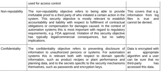
The following table [MaNa04] gives a detailed description of these items.
Security objective
Description Benefits
Availability Availability refers to ensuring that unauthorized persons or systems cannot deny access/use to authorized users. For automation systems this refers to all the IT elements of the plant, like control
The network and connected sys-tems shall be able to
systems, safety systems, operator workstations, engineering workstations, manufacturing execution systems, as well as the communications systems between these elements and to the outside world. Violation of availability may cause safety issues, as operators may lose the ability to monitor and control the process. This may also lead to severe loss of production.
transport data and respond to any requests wit-hin an expected time.
Third party protection
The third party protection objective refers to the prevention of damages effectuated to third party systems caused by an unexpected and mainly unintended behavior of the own IT system. This type of security objective will not refer to damages of the own system or safety hazards of the controlled plant. A successfully attacked and subverted automation system could be used for various attacks on the IT systems or data or users of external third parties, e.g. via distributed-denial-of-service (DDOS) or worm attacks. Consequences could reach from a damaged reputation of the automation system owner up to legal liability for the damages of the third party. There is also a certain probability that the attacked third party may retaliate against the subverted automation system causing access control and availability issues. This type of counter attack may even be legal in certain jurisdictions.
A failure of a single device or service shall cause no harm to others.
Integrity The integrity objective refers to preventing modification of information by unauthorized persons or systems. For automation systems this applies to information coming from and going to the plant, such as product recipes, sensor values, or control commands, and information exchanged inside the plant control network. This objective includes defense against information modification via message injection, message replay, and message delay on the network. Violation of integrity may cause security as well as safety issues, whereby, equipment or people may be harmed.
A user can be sure that his data was not modified, is complete and with respect to the sender correct.
Auditability Auditability is concerned with being able to reconstruct the complete behavioral history of the system from historical records of all (relevant) actions executed on it. While in this case it might very well be of interest to record also who initiated an action, the difference between the auditability security objective and non-repudiability is the ability of proving the actor identity to a third party, even if the actor concerned is not cooperating. This security objective is mostly relevant to discover and find reasons for malfunctions in the system after its occurrence, and to establish the scope of the malfunction or the consequences of a security incident. In the context of automation systems this is most important in the context of regulatory requirements, e.g. FDA approval. Note that auditability without authentication may serve diagnostic purposes but does not provide accountability.
This covers that e.g. information from log files is complete and can be tracked.
Authorization The authorization objective, also known as access control, is concerned with preventing access to or use of the system or parts by persons or systems without permission to do so. In the wider sense authorization refers to the mechanism that distinguishes between legitimate and illegitimate users for all other security objectives, e.g. confidentiality, integrity, etc. In the narrower sense of access control it refers to restricting the ability to issue commands to the plant control system. Violation of authorization may cause safety issues.
Only authorized communication
partners can access the device. Beside malicious attacks this measure can protect against problems caused by accidental access.
Authentication Authentication is concerned with determination of the true identity of a system user (e.g. by means of user-supplied credentials such as username/password combination) and mapping of this identity to a system-internal principal (e.g. valid user account) under which this user is known to the system. Authentication is the process of determining who the person is that tries to interact with the system, and whether he really is who he claims to be. Most other security objectives, most notably authorization, distinguish between authorized and unauthorized users. The base for making this distinction is to associate the interacting user by means of authentication with an internal representation of his permissions
This covers the determination of the identity of a communication partner, which is necessary for authorization.
used for access control
Non-reputability The non-reputability objective refers to being able to provide irrefutable proof to a third party of who initiated a certain action in the system. This security objective is mostly relevant to establish accountability and liability with respect to fulfillment of contractual obligations or compensation for damages caused. In the context of automation systems this is most important with regard to regulatory requirements, e.g. FDA approval. Violation of this security objective has typically legal/commercial consequences, but no safety implications.
This covers that e.g. information from log files is true and cannot be denied.
Confidentiality The confidentiality objective refers to preventing disclosure of information to unauthorized persons or systems. For automation systems this is relevant both with respect to domain specific information, such as product recipes or plant performance and planning data, and to the secrets specific to the security mechanisms themselves, such as passwords and encryption keys.
Data is encrypted with an appropriate algorithm and a user can be sure that no third-party has accessed this data.
2.2 Security Classification
Almost everybody in industry knows the IP - Industrial Protection classes, describing the robustness of device against dust and water.
An approach of a similar, easy to understand classification for security needs and features called SecIE Security Classes has been proposed by the SecIE and is shown in the figure below.
Classification
none low-medium high very high
Integrity log data
failure events repeat data, use checksum rare failure acceptable, production loss no failure acceptable, severe production loss
Non-repudation no measures store access
information to log files use authorization and backtrace use of certificates and secure servers
Confidentiality data are public
available, not protected use basic mechanisms, single failure may occur secure data chanels, active protection encrypted data, failures are not
acceptable Availability no measures, downtime: some hours using backup, downtime: <1h quick replacement, downtime: <5min redundant system, no downtime
Authentication without any
access control
using passwords using server based user authentication
use of certificates, smart-cards, etc. Figure 1: Security Classification
The SecIE Security Classes map the five security criteria Integrity, Non-repudiation, Confidentiality, Availability and Authentication described within the previous subchapter to four classes of importance (security levels) ranging from none over low-medium to high and very high. Each class describes several measures that have to be taken to fulfill the security requirements of the class.
Based on the SecIE Security Classes a mapping of security requirements of a system to security measures of the used security architecture and available security functionalities and mechanisms of devices and communication protocols is possible.
The following examples explain the application of these classes to more real-world examples.
2.2.1 Security Classification Example - Light Bulb Factory
Within the following example the Classified security level "none" will be considered.
Let's assume a production of few different types of light bulbs. The factory manufactures a few thousands of a kind to fill their stock and needs then some time to switch production to another type.
The factory communication system is an completely Ethernet TCP/IP based communication system and its is not connected to any other Ethernet based system.
Data integrity is no problem within the example factory, because every device is using TCP/IP communication, making sure that data is delivered and in the right order.
Non-repudiation is no problem within the example factory, because the production network is an isolated network, without any connection to Office IT or the Internet.
Confidentiality is no problem within the example factory, because data consists only of process data images, unauthorized people have no access to the network and there is no need to protect this data.
Availability is no problem within the example factory, because we have floor personnel available to solve every problem within one hour and since production is buffered by the company's stock, some downtimes are acceptable.
Authentication is no problem within the example factory, because access to the shop floor is controlled and without a PLC programming device, someone cannot manipulate anything.
Conclusion: This is a cheap production line, using Industrial Ethernet just to save money and without any need of sophisticated security mechanisms.
2.2.2 Security Classification Example - Automotive parts
Within the following example the Classified security level "medium" will be considered.
Let's assume now a plant for just-in-time manufacturing of automotive parts using an Ethernet TCP/IP based communication system. The system is protected by a firewall-gateway and an access control mechanism.
Data integrity is ok within the example factory, because every device is using TCP/IP, making sure that data is delivered and in the right order - or UDP/IP for some configuration services.
Non-repudiation is ok within the example factory, because the production network is using a firewall-gateway to the office network, allowing only HTTP. Access to devices is controlled by login (user/password) and this information is locally stored. A dedicated modem allows remote service without bridging into the office network.
Confidentiality is no problem within the example factory, because unauthorized people have no access to the network and the data is not important enough to spend much money on encryption. Availability is no problem within the example factory, because the firewall protects the network from unwanted traffic and overload. Physical access to the production network is only allowed to registered service people. In case of failure, replacement devices are available, backups are frequently made on a server and the personal is well-trained.
Authentication is ok within the example factory, because access to devices requires the user to login with username and password, this information is not public available, every with granted access has signed a letter of confidence.
Conclusion: This company is running production 24/7 - any downtime problem can be fixed within one hour, with remote service, an expert hotline can access some machines and assist. The risk of security leaks is quite low, the company has an internal handbook for security events.
2.2.3 Security Classification Example – Pharmaceutical process
Within the following example the Classified security level "high" will be considered.
This example addresses a company manufacturing medical or pharmaceutical products. Failures are not acceptable at all, many procedures are required by law. The communication system is based on an Ethernet TCP/IP network. The network is protected by special devices, special topologies, special access control mechanisms, data encryption, and special internally used protocols.
Data integrity is guaranteed by using IP-based protocols. In addition, the network data flow is monitored to detect anomalies, packet-smoothers avoid overflow and bandwidth problems. Rules were set to describe the “normal” behavior of the network and in case of anomalies, there is an instant notification.
Non-repudiation: is required by law to track any intervention. Any personnel has security clearance and access (physical as well as virtual) is controlled by smart-cards, login information is stored on redundant servers, using RADIUS.
Confidentiality: Production data needs to be encrypted, because this know-how is vital to the company. Any network data outside machines is using data encryption, at least IPSEC. People with access to the machines have security clearance and are frequently trained. Any failure might cause espionage and result in severe financial loss.
Availability is highly needed because production downtimes of single machines affect the whole production process. Redundant PLCs are used as well as redundant network topologies.
Authentication is important, any unauthorized access has to be prevented. Identification of floor personnel is controlled by security staff and using state-of-the-art access technology.
Conclusion: Proper network operation is highly important to this company. They need to be able to track anything any failures is not acceptable.
2.3 The IP protocol family
After defining the term “Security” by describing the objectives intended by security activities, mechanisms, and architectures and given examples on the classification of Security measures within the following chapter basic information about the most used Ethernet based protocol family, the IP protocol family; will be provided.
Today, large communication between networks is driven by the Internet Protocol (IP) family. Whether an eMail is sent or a web site is visited, the data flow is controlled by IP. Even the largest network of the world, the Internet, uses these protocols and shows obviously, that IP has proven its capabilities for exchanging high volumes of traffic dependably. Also, in automation networks, IP is widely used for high traffic communication between different automation cells, MES and the office world. However, there are known problems caused by design flaws in the IP family which can cause security problems.
Thus, this chapter will give a short introduction into the design of the IP family and describes some resulting security flaws. For more information on the IP family please also refer to the IAONA Handbook Industrial Ethernet [IndI06].
2.3.1 Design of the IP family
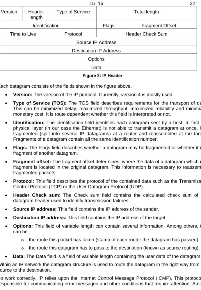
To understand security related problems of IP, a basic knowledge of the IP design is necessary. The figure below shows the structure of an IP packet (also called datagram). Since this section
provides only a basic introduction to the topic, only the most important fields for understanding the functionality are described. For a detailed description of IP, please refer to [Stev94].
0 15 16 32
Version Header length
Type of Service Total length
Identification Flags Fragment Offset
Time to Live Protocol Header Check Sum
Source IP Address Destination IP Address
Options Data
Figure 2: IP Header Each datagram consists of the fields shown in the figure above.
• Version: The version of the IP protocol. Currently, version 4 is mostly used.
• Type of Service (TOS): The TOS field describes requirements for the transport of data.
This can be minimized delay, maximized throughput, maximized reliability and minimized monetary cost. It is route dependent whether this field is interpreted or not.
• Identification: The identification field identifies each datagram sent by a host. In fact the
physical layer (in our case the Ethernet) is not able to transmit a datagram at once, it is fragmented (split into several IP datagrams) at a router and reassembled at the target. Fragments of a datagram contain all the same identification number.
• Flags: The Flags field describes whether a datagram may be fragmented or whether it is a
fragment of another datagram.
• Fragment offset: The fragment offset determines, where the data of a datagram which is a
fragment is located in the original datagram. This information is necessary to reassemble fragmented packets.
• Protocol: This field describes the protocol of the contained data such as the Transmission
Control Protocol (TCP) or the User Datagram Protocol (UDP).
• Header Check sum: The Check sum field contains the calculated check sum of the
datagram header used to identify transmission failures.
• Source IP address: This field contains the IP address of the sender.
• Destination IP address: This field contains the IP address of the target.
• Options: This field of variable length can contain several information. Among others, this
can be
o the route this packet has taken (stamp of each router the datagram has passed) o the route this datagram has to pass to the destination (known as source routing).
• Data: The Data field is a field of variable length containing the user data of the datagram.
Within an IP network the datagram structure is used to route the datagram in the right way from the source to the destination.
To work correctly, IP relies upon the Internet Control Message Protocol (ICMP). This protocol is responsible for communicating error messages and other conditions that require attention. Among
others, this includes information about unreachable destinations, traffic rates that the target cannot cope with (called a source quench), or bad headers in IP datagrams.
One well-known application of the ICMP is the ping command which is used to determine whether a host is reachable via the network. Therefore, ping issues a special ICMP packet (called “echo request”). If the host receives such packets, it replies with an “echo reply” showing that it is able to communicate over the network.
2.3.2 Security Problems of IP
There are a couple of problems resulting from the way, the IP protocol family works. In this section, two exemplary problems, acting as references for the majority of problems, will be described. The first considered problem of the design of IP is the non-reliability of the authenticity of a source address. This non-reliability results from the specification of the IP protocol family.
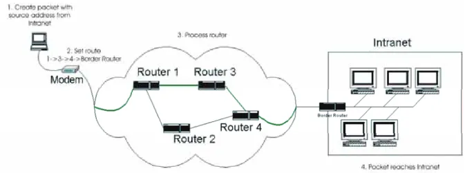
A very popular approach to attack networks based on the non-reliability of the authenticity of a source address is to fake the source address of an IP packet (IP Spoofing) as illustrated in the figure below.
Figure 3: Source Routing
An external device will create a packet with an source address used within the Intranet. Using the possibility of the definition of the router path the packet has to follow to its destination by a special option in the option field of the packet (the so called Source Routing of the IP protocol) the packet will be routed to the borders of the Intranet. The packet with the bogus address then appears at the router network card connected to the Internet and the routing forwards this packet to the internal network card. The target system will finally receive the packet as a packet from one partner within the Intranet. Using this method a system outside the Intranet can pretend to be a system within the Intranet without recognition by the Intranet members.
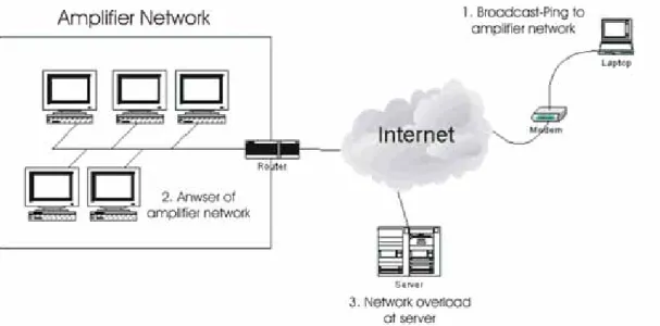
In this way one can create network traffic within the Intranet, the causer seems to origin from the local network. A corrupt router implementation may forward the normally not routable packet to the target without checking the impossible source address. It has to be mentioned that some large Internet provider still allow IP spoofing so this is an up-to-date problem. Recognizing faked packets from the Intranet is much more difficult since the alleged originator may be the real originator. Another problem are amplifier networks depicted in the figure below.
Figure 4: Amplifier Network
An ICMP packet with a faked source address will be forwarded to a broadcast address of a network. Bad configured router allow the forwarding of the packet, the consequence is the answer of all active hosts within the local network to the faked source address. The target host will be flooded with packets and can not answer to normal traffic (Denial of Service, DOS). With a large amplifier network you can interfere a T1 connection (1.544 mbps) with just 14.400baud modem. In this context its interesting that bad configured network components can cause this problem by just a type.
2.4 Communication relations in an enterprise network
When setting up the protection of a network, it is important to realize what communication relations exist in a company, between company sites and to the outside world and which of these relations have to be protected. Therefore this section analyses a generic company network and explains the communication within.
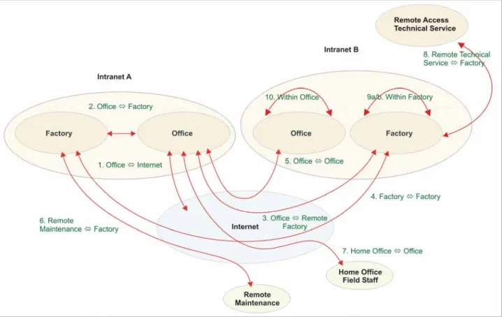
The next figure shows two company sites (Intranet Company A & B) and several remote access points to these company sites. The communication between the companies and to the remote access points takes place via the Internet.
The common architecture of larger company networks consists of different Intranets that communicate over the Internet. The term Intranet describes in this context a local area network (LAN) that offers the most common services that are known from the Internet like Domain Name Service (DNS), E-Mail (SMTP, IMAP, POP3) or web servers (HTTP, HTTPS) based on the IP protocol suite. Within the Intranet two logical subnetworks exist: Office and Factory. Every Intranet represents a branch of the company.
Figure 5: Communication relations of a company network
The office network consists mostly of common PC technology equipped with Ethernet network interfaces used to fulfill common management tasks. The most common factory relevant applications within this area are office applications of the ERP level. The mostly used Ethernet based protocols are the usually known Internet protocols like ordinary Ethernet TCP/IP, HTTP, FTP, and others.
The factory network represents the different production facilities within a branch and connects the different production units with its devices to a proper behaving production control system. The data transmitted within the factory network are produced by different levels of control applications ranging from typical the Manufacturing Execution System (MES) applications like order management or tool management over quality assurance applications down to real-time control applications within a special manufacturing cell. Also used applications within the factory network are maintenance and service applications. The protocols used within the factory network are the same as in the office network but extended by special industrial Ethernet protocols like EtherNet/IP, Modbus/TCP, Ethernet Powerlink, EtherCat, and Sercos III, reflecting the different real-time requirements of industrial control systems.
In this context the Internet is treated as a large network of interconnected networks defined by the Internet Engineering Task Force (IETF) in the Request for Comment (RFC) 2026 as a loosely-organized international collaboration of autonomous, interconnected networks, which supports host-to-host communication through voluntary adherence to open protocols and procedures defined by Internet standards.
According to the figure above showing a distributed network of a company the different communication relations will be described.
Communication relation
Content Time constraints
1: Office ⇔ Internet The office PCs communicate with the Internet to access information resources that are located in this network e.g. accessing web servers (HTTP) or download files (FTP).
Non time critical
2: Office ⇔ Factory ERP (Office) and MES (Factory) communicate with each other for coordinating manufacturing processes.
Slightly time critical
medium volume
3: Office ⇔ Remote Factory
ERP (Office) and MES (Remote Factory) communicate with each other for coordinating manufacturing processes.
Slightly time critical
medium volume
4: Factory ⇔ Factory To coordinate production processes between different production facilities, the MES of the facilities must communicate with each other.
slightly time critical
medium volume
5: Office ⇔ Office Office application must share data between the branches for example sharing documents, coordinating management processes, or exchange data between ERP application parts
non time critical
high volume
6: Remote
Maintenance Factory
For remote maintenance manufacturers must access devices within the factory network. This could be done via Internet, Intranet or right away in the factory
non time critical
medium volume
7: Home Office/Field Staff ⇔ Office
Home Office workers and field staff members must access and share their data within the office network.
non time critical
high volume
8: Remote access of technical service ⇔ Factory
A technical service provider may access the factory bringing with him a PC, a device or only a storage unit
non time critical
medium volume
9a: Within factory To coordinate the manufacturing process the MES system has to exchange data with the field control devices within the factory floor control system
slightly time critical
medium volume
9b: Within factory To control the manufacturing process different control system devices will exchange data.
high time critical
low volume
10: Within office Office applications must share data within the office network for example sharing documents, coordinating management processes, or exchange data between ERP application parts
non time critical
high volume
2.5 Network architecture for Industrial Ethernet
Though a standard for wiring office networks is well established, currently there exists no adopted standard for Ethernet networks in the factory environment. To overcome this problem the Joint Technical Working Group (JTWG) “Wiring Infrastructure” of IAONA modified the standard for structured IT cabling according to EN 50173 and ISO/IEC 118101 to fit the special purposes of factory networks.
The work has resulted in the “IAONA Industrial Ethernet Planning and Installation Guide” [IAONA03] which describes the architecture needed for the special requirements of a factory level network. Based on this guide IAONA has initiated the standardization of wiring industrial networks within IEC where first draft standards will be available.
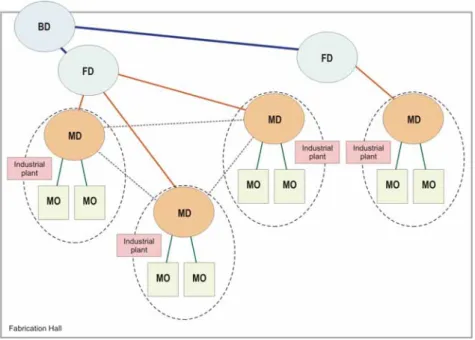
The following figure has been taken from the “IAONA Industrial Ethernet Planning and Installation Guide”. It describes the architecture of such a network and especially introduces the Machine Distributor (MD):
Figure 6: Fabrication hall with ring topology
Not shown in the figure above, the basic element of a production plant is the campus distributor (CD) which consists of level-3-switches, an alternative to the common backbone technology that eliminates the router bottleneck of conventional network architectures by integrating routing functionality in the switch.
The figure above shows the three layered architecture of fabrication hall as specified in the “IAONA Industrial Ethernet Planning and Installation Guide”. A factory hall is connected to the campus distributor via the building distributor (BD) which provides access to the floor distributors (FD). The machine units themselves are connected via the machine outlets (MO) to the machine distributors (MD) which in turn are connected to the floor distributors (FD). To provide fail save connectivity a hierarchically interlinked ring topology can be established which can bypass single failures of network connections.
Every distributor can be considered as an own sub-network to reduce network traffic between the different network segments that even occur with the application of switches especially in the case of broadcast messages.
Since traffic within the MD sub-network is used for control purposes of the machine units (communication scenario 9b of subchapter 2.4) hard real-time requirements must be met to guarantee secure operations. On the other hand it may be necessary to transmit data between different MD sub-networks e.g. in the case of work piece handover.
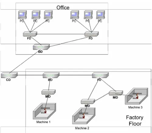
Figure 7: Example of a network topology
The figure above shows the case of integration of a new production system based on 3 machines containing distributed intelligence, i.e. intelligent sensors and actuators with Ethernet enabled Onboard-PLCs.
The different buildings (office, floor) are connected to the backbone via Building Distributors (BD). Within a factory building, the different elements such as the are connected to the network via Floor Distributors (FD) and Machine Distributors (MD).
Within the office building additional Floor Distributors (FD) are installed to connect the floors of the building with the local backbone.
The local backbone is connected to the overall backbone of the company or the Internet via a Campus Distributor (CD).
2.6 Defense strategy
When dealing with network security, an important issue forms the strategy of defending a network against outside attackers. Nowadays, two concurrent approaches are used in the IT world [MaNa03b]:
Hard-perimeter
Defense-in-depth
Within the following sub-chapter both approaches will be described in detail to provide a basement for further understanding of the SecIE network security approach.
2.6.1 Hard-perimeter
The Hard-perimeter approach focuses on a impenetrable wall around the system. The complete internal network system will be connected with the Internet via a single security device or a single security device set (depending on the implementation). Any communication between Intranet and Internet has to pass this single connection point and will be observed with respect to the implemented security objectives.
Despite its simplicity this approach faces some serious problems. Among others these are [8]:
Monocultures: This approach is based on one single methodology for securing a system. If the methodology fails, then the whole approach fails.
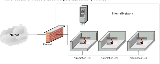
Communication ports: The systems must have communication ports for communication with other systems. These entries are potential security threads.
Figure 8: Hard perimeter
A simple example of a hard perimeter can be seen in the picture above. An internal network consisting of several automation cells and a MES application represents a local production facility. To coordinate production between different production facilities and to provide remote maintenance capabilities, the system is connected to the Internet via a firewall. This firewall represents the hard perimeter: If an attacker is able to circumvent the firewall, the network is completely open for attacks.
2.6.2 Defense-in-depth
An alternative approach to the hard-perimeter, named defense-in-depth, replaces the single system security philosophy by a multi-level security system. It builds several zones for network security, each one equipped with a different security methodology and different security relevant devices (maybe provided by different device vendors). The shell system resulting from this approach shows a higher complexity but provides several advantages:
Different security technologies raise the time necessary for intrusion
The different stages allow different mechanisms for security defense e.g. for intrusion detection
The raised intrusion time allows a better recognition of intrusion
The picture below shows the production facility from the example above with a more complex security system using the defense-in-depth approach.
To infiltrate the network, now the attacker has to bypass several security measures. First, he has to circumvent the first packet filter which has been implemented by a vendor A. Then, he has to take over the Application Gateway. An application gateway is used to decouple networks logically and physically. To communicate with a communication partner outside the internal network, any component from the internal network connects to the Application Gateway. The Application Gateway analyses the traffic, checks for any suspicious or forbidden action (e.g. accessing illegal content on a web server) and forwards the data to the destination. In the direction of the internal network, the Application Gateway is protected by a packet filter from vendor B. Finally, the Automation Cells are additionally protected by a packet filter.
Using different products in a defense-in-depth system can raise the security: If a security flaw is found for the packet filter of vendor A, the packet filter of vendor B is still secure.
2.7 Security Components
To implement a security system within the network additional devices implementing special mechanisms have to be integrated. Therefore, several components and concepts exists, that can help to secure an Industrial Ethernet network. The following sub-chapter will give a brief introduction to the most important concepts of a Packet Filter, an Application Gateway and a Demilitarized Zone (DMZ).
2.7.1 Packet Filter
A packet filter analyses and controls each individual incoming or outgoing packet passing a network border system and decides, using a rules table, whether a packet is valid and has to be forwarded or it should be dropped [Le03].
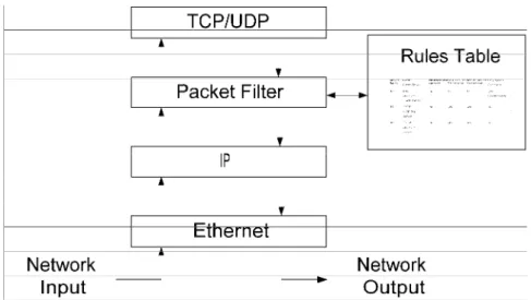
The packet filter can be integrated either within a sub-net bordering system representing an entry point to the sub-network or within the entrance system (network card) of an individual device. In both cases the entrance is protected by observing the packet flow through the system border. The packet filter itself is integrated within the Ethernet TCP/IP protocol stack of the network cards used. The scheme of the integration of a packet filter is shown in Figure 10.
Figure 10: Concept of a Packet Filter
It can be seen, the a packet filter is located between the basic IP functionality and the TCP/UDP part of the IP stack. If an IP packet is received by a packet filter device, the packet has to pass a basic sanity check by the basic Ethernet and IP functionality (calculating checksum, comparing size of the header etc.). As a next step, the packet is forwarded to the packet filter code. The filter now decides based on a set of rules whether to allow the the packet to proceed or to drop. If the packet is allowed to proceed, it is forwarded to the TCP/UDP part of the IP stack.
• IP Source address
• Source port
• IP Target address
• Target port
• TCP packet type (Synchronize, Acknowledge etc.)
In general, packet filters follow two different approaches when dealing with its rules. The first one, called “Deny”, drops all packets that are not explicitly allowed by a rule in the rules table. The source of the address will be informed using the ICMP protocol. The second one, called “Drop”, simply discards all packets that are not allowed by the rules without notifiy the packet source. The following example shows a simple application of this concept.
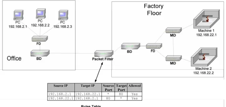
Figure 11: Packet Filter Example
Figure 11 shows a network split into two parts: an office network containing several workstations and a factory floor containing two machines. For the office network, it shall only be allowed for the PC with the address 192.168.2.1 to access the web server of Machine 1 with the address 192.168.22.1. Thus, the rules table of the packet filter contains two rules:
First, allow packets from 192.168.2.1 with any source port to 192.168.22.1 with target port 80, which is the standard port for HTTP (see annex 0). HTTP is based on TCP which result in a bi-directional communication. Thus, it is necessary to allow the way back or the PC will never receive the requested web page. This is done using the second rule: Allow packets from 192.168.22.1 with source port 80 to 192.168.2.1 with any target port.
Any other packet that tries to pass the packet filter will be discarded.
A more sophisticated king of packet filter are the dynamic packet filter, also called state full inspection. The example above has one main disadvantage. Any packet from Machine 1 is allowed to pass to the PC as long as the source port is set to 80. Dynamic packet filter provide a way to filter packets depending on connections. For the example above, a dynamic packet filter would only allow packets from the machine to the PC that belong to a connection which was established by the PC. In this way, only data that belongs to the requested web page is delivered. Any other packets are discarded by the packet filter.
2.7.2 Application Gateway
An Application Gateway is able to inspect protocols on the fly and can decide, based on a ruleset, which commands in a protocol are allowed and which ones have to be denied [Bre01]. Figure 12 shows the schematic structure of an Application Gateway.
Figure 12: Application Gateway
As can be seen, an Application Gateway works on top of the IP stack. For each protocol, a so called proxy containing an analysis module has to be installed, that is able to analyse the protocol. A proxy reads data from the network, reassembles the whole command and analyses it. If the command is allowed to proceed according the the rules table of the proxy, the data is then sent to the target. Further on, it is possbile to filter out given content type such as, in case of web sites, Java Script or Java Apllets. This procedure allows a logical and physical decoupling of connections between source and target.
One disadvantage of this security component is the fact, that only standard protocols such as HTTP or SMTP can be secured since only proxies for those protocols exist. Other protocols cannot pass the Application Gateway. At the moment, there are no known proxies for Industrial Ethernet protocols such as EtherNet/IP or Modbus/TCP.
Optionally, an Application Gateway can be extended with further components such as Logging facilities or User authentication.
The following figure shows an example of the usage of an Application Gateway.
The example above reuses the network example from section 2.7.1. This time, the networks are not decoupled by an Packet Filter but by an Application Gateway. If the user of the PC with the address 192.168.2.1 tries to acces the web page on the Machine 1, the request has to pass the Application Gateway. The Application Gateway analyses the incoming command and checks against its rules table, whether the command is allowed. A simple retrieval of a web page is normaly done using the GET command of the HTTP protocol. According to its rules table, this command is allowed. Thus, the request will be forwarded to the Machine 1 and also the reply will be allowed. Additionally, an Application Gateway is able to inspect the contents of web page. In case the web page contains a Java applet for configuring parameters of Machine 1 which should only be accessible from within the Factory Network, the Application Gateway can filter out such contents, so this applet is not accessible from the office network.
In case, the user of PC of the office network tries to store a web page on the Machine 1 using the PUT command, this will be denied by the application gateway.
2.7.3 Demilitarized Zone (DMZ)
A Demilitarized Zone (DMZ, also called Screened Subnet), is a decoupled, isloated network that is integrated between two networks to decouple an unsecure network from a secure network [Mai03].
Figure 14: Demilitarized Zone (DMZ)
The DMZ is protected by two packet filters. The outer packet filter (the one directed to the insecure network) protects the DMZ against attacks from the insecure networks and also protects components located within a DMZ.
The inner packet filter protects the DMZ against attacks from the secure network, which can happen e.g. in case of virus spreads in devices of the secure network. Additionally, the packet filter provides another barrier for attackers that try to access the secure network in case that the protection of the outer packet filter fails.
Optionally, within a DMZ an Application Gateway can be integrated. The location within a DMZ offers additional protection for an Application Gateway.
A more complex application scenario for a DMZ is discussed in section 3.4.
2.7.4 Switches
A well-known problem of Ethernet networks are broadcast which can cause a high amount of traffic and may influence the performance and functionality of the system. Thus, it is necessary to restrict broadcast load on the system. Most modern switches provide functionality to influence the maximum broadcast load on the systems, thus the definition of network load limits or early warning systems for increasing network load can be done via the infrastructure components (e.g. MD, BD, see section 2.5) and need no additional security components.
2.7.5 Router
Router as fundamental infrastructure components of IP based networks have also possibilities to support the security of the communication.
In section 2.3.2, we have described special attacks that are based on flaws in the IP protocol, especially issues with faked addresses and source routing. Routers can be configured to only route packets with valid addresses and thus help to reduce such attacks.
The figure below shows, how a router can account for network security. It depicts a router that is connected to two networks:
• Network A with a network address of 192.168.22.0 and
• Network B with a network address of 192.168.2.0
Figure 15: Filtering packets with invalid addresses
As can be seen in the figure above, first a packet with a source address of 192.168.22.9 and a target address of 192.168.2.1 shall be routed. Since there is no evidence that the address is incorrect (the source address belongs to the connected network), the packet gets routed.
In the second case, a packet with a source address of 192.168.2.9 shall be routed to the destination 192.168.2.1. The router now recognizes that the source address does belong to the target network (network B). It is impossible that this packet comes from network A. Thus, the routing algorithm decides to discard the packet. In this way, a router can help to reduce problems resulting from address spoofing.
2.8 Differences between Office and Automation Networks
The following table illustrates differences between typical office and automation networks and devices.
The table addresses mainly client- or end-devices in the office or automation environment, such as users workstations or field devices. Highly concentrated server areas in the office IT can be compared to line controlling PLCs and may need a different point of view.
Office-IT Automation-Network
Network-Structures typical: redundant tree structures,
reconfiguration (if automated) / recovery within 1 minute
need recovery after physical network failures within 1 sec
Behavior on high network loads
best effort needs to limit network load (traffic
shaping, network balancer) to guarantee operation of devices
Real-time communication
defined by user's expectations, reaction time up to 1 minute may be acceptable
"real-time" conditions within automation networks can be < 1 ms (depending on devices and services)
Life Cycles Devices and Software may have life
cycles of typ. 3-5 years
devices and software have support and life cycles of typically > 10 years
Virus Scanning Performance drop is acceptable
Using updates and patches every few days or weeks are acceptable
is in most cases unacceptable inside automation networks and devices due to the fact, that side-effects and
performance issues are unknown
Support during life cycle is usually not possible
Device Performance outdated devices are easily replaced regarding life-cycles, performance of
devices may be statically limited
Power Consumption System design keeps care of modern
CPU's with high power dissipation.
System design may restrict device performance.
Redundant power supplies, fan less devices are required.
Patch Management Patch Management has higher priority
than device operation. Automated Update services are available.
Booting devices (and downtimes) is acceptable
Patch must not influence the device operation, must be tested prior to use.
Booting of devices must be avoided.
Availability / Downtime Failure of single or few devices may be
acceptable and does not cause any general downtimes.
Downtimes of a few minutes up to hours may be acceptable.
Failure of a single device may cause complete failure of production lines.
Downtimes are usually acceptable of up to 5 minutes.
Device replacement Replacement by software re-installation,
hardware replacement may take days.
Loss of user data may be acceptable.
Replacement by maintenance personnel
Device and software replacement is needed within few minutes,
No loss of user data and configuration.
No trained personnel available
Applications heterogeneous environment, type and
number of applications is determined by user's needs.
Harder to use certificates
well-defined and limited environment, use only applications needed for the device's operation.
possibility to "stamp" applications
Network protocols Need to use high number of protocols,
message formats and broadcast messages.
The number of automation protocols is restricted, thus, the network traffic can be restricted to use only defined TCP/IP and UDP/IP connections.
Hardware Platforms Mainly PC architectures using Windows
operating system
many hardware platforms and legacy systems, using a high number of different OS's, versions and network stacks
Communication relations
highly dynamic client server and peer-to-peer communications
high number of used protocols and ports
restricted number of communication relations.
possibility to control protocols and ports
The table above can help people to better understand the needs and requirements for Industrial Ethernet applications. Many products and solutions are based on developments made for and within Office IT - this discussion shall help to close the gap between these worlds.
It is important to understand, that industrial Ethernet is not as heterogeneous as Office IT is - and this makes some things easier - like identification and controlling of network traffic. On the other hand, some requirements of industrial Ethernet are hard to cope with when using Office IT equipment: usually the boot time of a device, which is typically some 10-20 seconds, is not even mentioned - but using such a device on a robots tool-changer, the machine has to wait 10-20 seconds before continuing its work, and this is a killing factor to use such devices.
3 SecIE Security Methodology
When setting up network security for Industrial Ethernet networks, the following methodology should be pursued by system integrators or network administrators.
This methodology follows a step by step process in which each step generates results which have to be used in the following step.
The following figure shows the overall process:
Process step Result
1. Security demand classification Needed security measures of the plant / system / etc.
2. Communication relations 1) Analysis which communication
relations are necessary for operation
2) Definition which communication relations are allowed
3. Defense Strategy Definition of defense strategy
4. Defense Structures Definition of defense structures
5. Devices & Protocols 1) Analysis of used protocols
2) Definition of allowed protocols
6. Defense measures 1) Definition of firewall / switch / router
rules
2) Definition of administrative rules e.g. for emergency cases, access of maintenance staff etc.
This methodology will now be explained in more detail in the following chapters.
Note: It is important to understand that this methodology does not have to be sequential. Each step may have influence on other steps. For example, it may be possible that some communication relations cannot be secured in the required way, thus, a new structure for the network has to be found.
3.1 Security demand classification
In order to define, what security demand a single system has, first it is necessary to define a set of categories on which a malfunction of a device can have effects on:
affects production
describes the effects of a failure of a service or device on the production environment
user safety (health and life)
describes how a failure may effect the safety of a user
affects privacy (access to person-related data)
describes how a failure may lead to a violation of person-related information
affects company image, publicity
describes how a failure may cause damage to the company image
financial loss
describes how severe the financial loss due to a failure may be
violation of contracts/laws
describes how a failure may lead to a violation of patent rights or confidential data
The following table is showing what behavior may be acceptable for a certain category, depending on the security level (non, low-medium, high and very-high). The details in these sections, especially downtimes, are only suggestions and may be discussed individually.
Security Level
None low-medium high very-high
affects production
any effect on production /
breakdown is possible
stop and restart time doesn't matter
local, partial breakdowns are acceptable
downtime does not exceed 6 hours loss may be compensated thru manual workers, buffering products, repeating of transmission etc. local, partial breakdowns are acceptable
downtime does not exceed 6 hours loss may be compensated thru manual workers, buffering products, repeating of transmission etc. no breakdowns are acceptable
downtimes are not acceptable
loss cannot be compensated
user safety no effects any effect is not likely any effect is not likely failures are likely to affect safety systems
affects privacy
no personal data present, all data is public
personal data is present, access through other persons is possible and may be accepted, no loss of social state
personal data is present, access through other persons is possible and may be accepted, no loss of social state
personal data gets lost, tracking not possible
loss of social state
affects company
neutral only internal only internal information about the
failure is public
financial loss not relevant within budget / calculation
within budget / calculation
severe financial damages
threatens the company
contracts/ laws
limited damages limited damages cause legal suits
Based on the table above the user can define his necessary Security Level. This is done by
checking for each item which of the four possible effects is true. The required overall Security Level is the highest marked security level of any category.
This example shows how the definition of security terms may be used on an IO-device.
Classification
affects production low-medium
failure can easily be detected
replacement with spare parts in short time
user safety none
this device does not interfere the overall safety circuits
affects privacy none
does not collect any personal data
affects company low-medium
unlikely to have any external effect
financial loss low-medium / high
cost for spare part and replacement
diagnostic and restart may be cost intense
violation of contracts/laws low-medium
contracted availability may be affected
In this example, the necessary Security Level for the system would be low-medium / high due to the possible effects regarding financial losses.
3.2 Communication relations
As a second step, the different communication relations which are needed for the operation of the production system need to be analyzed. This analysis can be done using the proposed generic communication relations given in chapter 2.2 of this handbook (please refer to the template in chapter 6).
For the analysis of the communication relations the template can be gone through and all irrelevant data can be removed. The following table is an example of a filled out communications relations table:
Communication Relations Table
Project:
Example
Date:Communication relation type (According to SecIE Handbook of Network Security - Chapter 2.4)
Comment Classification
1: Office ⇔ Internet There is no need to access the internet, however it can be allowed (as usual)
Optional
2: Office ⇔ Factory Communication SAP to MES Necessary
3: Office ⇔ Remote Factory Only one factory Not applicable
4: Factory ⇔ Factory Only one factory Not applicable/
5: Office ⇔ Office Only one factory Not applicable
6: Remote Maintenance ⇔ Factory Not planned yet Optional
7: Home Office/Field Staff ⇔ Office No need for that Not applicable
8: Remote access of technical service ⇔ Factory
Due to security considerations Forbidden
9a: Within factory Ethernet is used as communication bus Necessary
9b: Within factory Ethernet is used as communication bus Necessary
10: Within office Ethernet is used in the office Necessary
Communications Relations Table complies with the SecIE Handbook of Network Security (Version 1.3)
Necessary: A communication relation is necessary for operation and has to be established. If this communication relation is not established, the system might not work.
Optional: A communication relation is not necessary for operation. If this communication relation is not established, the system will still work.
Forbidden: A communication relation is not allowed. If this communication relation is established, the system might not be protected against attacks from this communication relation.
Note: This step is strongly depending on the starting point of planning the network security activities. If an already established network shall be secured based on this methodology, the table described above acts as the documentation of the structure of the network and the resulting communication paths for the communication relations. This documentation provides a basis for planning defense structures (c.f. section 3.4) and defense measures (c.f. section 3.6).
In case, a new network shall be secured it is strongly recommend to plan the network in strong collaboration with the planning of the defense structures c.f. section 3.4) and measures (c.f. section 3.6).
3.3 Defense Strategy
Based on the results of chapter 3.2 now the defense strategy has to be defined. Thus, the question, whether a defense-in-depth approach (cf. section 2.6.2) or a hard perimeter (cf. section 2.6.1) approach has to be answered.
The choice of the defense strategy of course is subject to the user’s individual security tolerance, a general guideline can hardly be given. The next table tries to summarize the important points which should be considered when choosing a strategy.
Aspect Hard-perimeter Defense-in-depth
Security Demand Minor threat
Minor possibilities for damage
Serious threat
Possibilities for damage
Communication relations Only few communication relations to the outside
Multiple communication relations to the outside
Communication structure Only few (one) access point to the network
Multiple access points to the network (internet, wireless, sneaker net, etc.)
3.4 Defense Structures
Based on the Defense Strategy, now the Defense Structures need to be specified. This means, how the defense will take place, e.g. by means of firewall, routers or switches and where are they positioned in the communication architecture. The requirements for the defense structures of a system result from its structure and its communication relations with its individual performance requirements (Real-Time, throughput etc). For planned networks, it is strongly recommended, to plan defense structure together with the whole network design.
For applying defense structures, the different elements described in section 2.7
• Packet Filter,
• Application Gateway,
• DMZ,
• Switches and
• Router
can be used. Based on the wiring example in Figure 7, some communication requirements and resulting security measures will be explained. The result is depicted in Figure 16.
The data within a MD subnetwork must be prioritized against network traffic from outer networks (e.g. traffic for web-based management) to guarantee soft real-time. This must be secured in both the case of malfunction and malicious actions. Therefore, a packet filter will be applied at the MD, that restricts the amount of incoming traffic from the building distributor.
The MD subnetworks must not influence each other. A mechanism is needed to guarantee a defined maximum delay between different subnetworks without influencing the behavior of the target network (throughput, delay, jitter). This must be secured in both the case of malfunction and malicious actions. Thus we configure the different switches in the network to reduce broadcast load. This functionality is additionally supported by the packet filter at the MDs. They are able to restrict the maximum amount of traffic between networks to a given value.