Institut für Mensch-Computer-Interaktion
Universität Stuttgart
Pfaffenwaldring 5a
70569 Stuttgart
Germany
Masterarbeit Nr. 3393
Mental Task Classification Using
Single-Electrode Brain Computer Interfaces
Mariam Hassib
Studiengang:
INFOTECH
Prüfer:
Prof. Dr. Albrecht Schmidt
Betreuer:
Alireza Sahami M.Sc.
Dipl.-Inform. Niels Henze
begonnen am:
02.05.2012
beendet am:
02.11.2012
iii
Acknowledgement
To my supervisors, Alireza Sahami and Niels Henz, thanks for all the help, advice, and motivation they gave. To Prof. Dr. Albrecht Schmidt for his guidance, and insight and for giving me the chance to be part of this amazing team. To the whole MCI department for being so friendly and helpful all the time.
To the girls who made me go through it all, Yomna, Mirna, Mahy, Christine and Azza, you made it feel likehome, thank you. To Michael, for being there on the desk in front of me smiling while working, your laugh is contagious, keep it forever. To Hallawa, a special thank you for you BCI passion and insight, and for your continuous brotherly help and support.
To my sister, Ghada, for every moment of support you have given me. For every breakfast, every cup of coffee, every jog, every spelling error, every smile and every weep, for every bit of it all, I would have never made it without you. Thank you for being there.
To Amr, my fiance, you have been through it all with me from day one, you have loved and supported me throughout this journey. You are one of a kind. May we always be happy and blessed together.
Thanks to all my friends back home: my best friend Nada, Maria, Eman, Kisho, Nouran, and everyone else who was always there to hear me out and offer their help.
Last but not least, thanks to God and thanks to the two people I cannot live without who made this all possible, and to whom I sincerely dedicate this thesis:
v
Abstract
In the recent years, the field of Human-Computer Interaction (HCI) has greatly evolved to involve new and exciting interaction paradigms that allow users to interact with their environment and with technology in a more intuitive and ergonomic way. These interaction paradigms include voice, touch, virtual reality, and more recently, the brain.
A brain-computer interface (BCI) is a an interface system allowing users to control devices without using the normal output pathways of peripherals, instead, by using neural activity generated in the brain. BCIs have a huge potential in a multitude of fields, all the way from providing users with severe motor disabilities with means for interaction with the external world, to entertainment, gaming, user state monitoring, and self tracking systems. The potentials of BCI have sparked the interest of researchers, gaming markets and healthcare providers more and more in the recent years. The is due to the emergence of new commercial lightweight, low cost Electroencephalograph (EEG) equipment that made it possible to create more portable and usable BCI systems and expanded their fields of application.
This Master thesis aims to explore the state of the art commercial BCI as well as the uses and challenges related to them. Commercially available EEG equipment, namely the Neurosky Brainband and Neurosky Mindset, will be investigated. User tests will be carried out to investigate whether
such equipment with low accuracy and low cost can be used to recognize various mental activities. This would be performed by first collecting a dataset of brain signals during performing a set of mental tasks, which is one of the contributions of this project, followed by applying a set of signal processing algorithms, then exploring various classification techniques to classify the collected signals.
vii
Contents
I Introduction and Motivation 1
1 Introduction 3
1.1 What is a Brain Computer Interface (BCI)? . . . 4
1.2 Commercial BCI Systems and Their Challenges . . . 5
1.3 Thesis Structure . . . 8
2 Motivation for Mental Task Classification 11 2.1 Communication and Control . . . 11
2.2 Neurofeedback and Rehabilitation . . . 13
2.3 Mental State Tracking . . . 14
2.4 Research Questions and Contributions . . . 15
II Background and Related Work 17 3 Biomedical Background 19 3.1 The Brain . . . 19
viii Contents
4 BCI Systems 27
4.1 EEG Signal Acquisition . . . 27
4.2 EEG Signal Processing . . . 30
4.3 EEG Feature Extraction . . . 34
4.4 EEG Signal Classification . . . 38
4.5 Commercial BCI Devices . . . 43
4.6 Weka: Open-source Classification Software . . . 46
5 Related Work 49 5.1 Task Classification using EEG Signals . . . 49
5.2 Commercial BCI Applications . . . 52
III Mental Task Classification 57 6 Data Acquisition and Feature Extraction 59 6.1 System Architecture . . . 59
6.2 Data Acquisition . . . 60
6.3 Pre-processing and Noise Removal . . . 66
6.4 Post-processing and Feature Extraction . . . 70
7 Data Classification and Evaluation 75 7.1 Visual and Statistical Data Analysis . . . 75
7.2 Data Classification . . . 80
Contents ix
8 Limitations and Shortcomings 99
8.1 Device Limitations . . . 99 8.2 Data Acquisition and Filtering Limitations . . . 100 8.3 Classifier Limitations . . . 101
9 Conclusion and Future Work 103
9.1 Conclusion . . . 103 9.2 Future Work . . . 106
xi
List of Figures
1.1 Components of a typical BCI system . . . 5
2.1 Semi-autonomous wheelchairs . . . 12
3.1 The 4 Lobes of the Cerebral Cortex . . . 20
3.2 The Neuron . . . 21
3.3 EEG, ECog, and Intracrotical Recording . . . 22
3.4 The raw EEG signal . . . 23
3.5 The P300 Speller . . . 26
4.1 Components of a BCI system . . . 28
4.2 10-20 electrode placement system . . . 30
4.3 EEG signal contaminated with EOG blinking artifacts . . . 32
4.4 Bayesian Network representing weather data . . . 40
xii List of Figures
4.6 An illustration of an Artificial Neural Network (ANN) . . . . 42
4.7 An example of an SVM with 2 classes . . . 43
4.8 Emotiv EPOC [Technologies,2012 (accessed October 19, 2012] 44 4.9 Left: NeuroSky MindSet, Right: MyndPlay BrainBand . . . 46
5.1 A conceptual illustration of a BCI during task classification of EEG signals . . . 50
5.2 NeuroPhone: Emotiv EPOC IPhone Application . . . 54
5.3 ThinkContacts: NeuroSky Mindset application . . . 55
6.1 System Architecture: 4 Modules . . . 60
6.2 Snapshots from the Android Application - Reading Test . . . . 63
6.3 Summary of Statistical Survey Data . . . 65
6.4 Subject seated wearing the Brainband device during the study 66 6.5 Corrupt NeuroSky Delta Power Value for Subject 2 . . . 68
6.6 Before and after artifact removal . . . 69
7.1 Comparison of Attention and Meditation means during the 5 tests . . . 76 7.2 Comparing NeuroSky Delta values during the 5 tests - Subject 6 77 7.3 Comparing NeuroSky Theta values during the 5 tests - Subject 6 77 7.4 Comparing NeuroSky Alpha values during the 5 tests - Subject 6 79 7.5 Comparing NeuroSky Beta values during the 5 tests - Subject 6 79
List of Figures xiii
7.6 Comparing NeuroSky Gamma values during the 5 tests - Sub-ject 6 . . . 79 7.7 Comparing the mean accuracy of classification of the baseline
task (Relax) to all other tasks in three settings . . . 96 7.8 Comparing the mean accuracy of classification of pairs of tasks
when using the fifth minute for testing (red) versus when using the third minute for testing (blue) . . . 97 7.9 Comparing the mean accuracy of classification of three tasks
when using the fifth minute for testing (red) versus when using the third minute for testing (blue) . . . 98
xv
List of Tables
1.1 Brain signal recording technologies and their disadvantages [Lee and Tan,2006] . . . 4
3.1 EEG Brainwave Types and Mental StatesNeuroSky[2009] . . 24
6.1 Summary of the features extracted from the collected signals . . 71
7.1 Subject Independent Classification - 10s Segments - No At-tribute Selection (31 Features) . . . 83 7.2 Comparison of baseline task (Relax) to all other tasks- 5s
Seg-ments - No Attribute Selection (31 Features) . . . 85 7.3 Comparison of the baseline task (Relax) to all other tasks - 1s
Segments - CFS feature selection was applied . . . 86 7.4 Comparison of pairs of tasks without the baseline task (Relax)
-1s Segments - CFS feature selection was applied . . . 87 7.5 Comparison of classification of 3 tasks: Relax, Read, Sudoku
with and without CFS feature selection using Bayesian Net-works and J48 Decision Trees - 5s Segments . . . 88
xvi List of Tables
7.6 Classification of three tasks using CFS feature selection - 1s segments . . . 89 7.7 Comparison of classification of baseline task (Relax) to all tasks
using the third minute for testing and applying CFS feature selection- 1s segments . . . 91 7.8 Classification of pairs of tasks without the baseline task (Relax)
using the third minute for testing and applying CFS feature selection - 1s segment . . . 92 7.9 Classification of three tasks using the third minute for testing
and applying CFS feature selection - 1s segments . . . 93 7.10 Comparison of classification of the five tasks using fifth minute
for testing versus third minute for testing and applying CFS feature selection - 1s segments . . . 94
xvii
List of Abbreviations
ADHD . . . Attention deficit hyperactivity disorder ANN . . . Artificial Neural Network
API . . . Application Programming Interface BCI . . . Brain Computer Interface
CNS . . . Central Nervous System CSV . . . Comma-Separated Values ECG . . . Electrocardiogram
ECoG . . . Electrocorticography EEG . . . Electroencephalography ERP . . . Event Related Potential FFT . . . Fast Finite Fourier Transform
fMRI . . . Functional Magnetic Resonance Imaging FNIRS . . . Near-infrared spectroscopy
GUI . . . Graphical User Interface HCI . . . Human Computer Interaction ICA . . . Independent Component Analysis MLPNN . . . Multi-Layer Perceptron Neural Network NFT . . . Neurofeedback Training
PCA . . . Principal Component Analysis SNR . . . Signal to Noise Ratio
SSVEP . . . Steady State Visual Evoked Potential SVM . . . Support Vector Machines
1
Part I
3
Chapter 1
Introduction
Human Computer Interaction (HCI) has been a constantly Using brain signals in the field of HCI has a wide paradigm of application
possibilities for both disabled and healthy users
evolving field in the recent years especially with the inclu-sion of new interaction paradigms including touch, voice and even virtual reality interfaces. A relatively new addi-tion to these paradigms is the brain. The ability to record electric potentials from the brain and translate them into real life commands to which a system would respond has recently been a growing interest for researchers. In addition, this newfound paradigm adds new dimensions to HCI. BCI, short forBrain Computer Interfaces, carries a lot of hope and potential for a very wide spectrum of scientists and researchers. It is going all the way from providing a better quality of life for people with severe motor disabilities [Kaur et al.,2012] to being the new fashion in the gaming and enter-tainment industry. In both cases, undoubtedly accompanied by many challenges, new findings and even more evolving fields of research and potentials will be appearing.
This Master Thesis aims to explore new emergent BCI inter-faces using off-the-shelf EEG devices, and their uses espe-cially in the field of mental task recognition.
4 1 Introduction
1.1
What is a Brain Computer Interface
(BCI)?
A brain-computer interface is a an interface system allow-EEG is the only
non-invasive, portable and affordable way to collect brain signals
ing users to control devices without using the normal out-put pathways of peripherals, instead, by using neural ac-tivity generated by the brain. The neural acac-tivity used in BCI can be recorded using invasive or non-invasive tech-niques. These techniques include Electroencephalography (EEG), Magnetoencephalography (MEG) functional Mag-netic Resonance Imaging (fMRI), functional Near Infra-red Spectroscopy (fNIRS), Electrocorticography (ECoG) and Sub-cortical Electrode Arrays (SEA) [van Erp et al.,2012]. The cost, effort, invasiveness and quality of these varying tech-niques can be summed up in table 1.1
Technology Disadvantage
Electrocorticogram (ECoG) Highly invasive, surgery
Magneto-encephalography (MEG) Extremely expensive
Computed Tomography (CT) Only anatomical data
Single Photon Emission Computed Tomography(SPECT) Radiation exposure
Positron Emission Tomography (PET) Radiation exposure
Magnetic Resonance Imaging (MRI) Only anatomical data
Functional Magnetic Resonance Imaging (fMRI) Extremely expensive
Functional Near-Infrared (fNIRS) Still in infancy,expensive
Table 1.1:Brain signal recording technologies and their disadvantages [Lee and Tan,
2006]
Figure 1.1 shows the different components of a basic EEG-The components of a
typical BCI system: Electrode Cap, Amplifier, Computer
based BCI system, which is of the non-invasive brain sensing technologies. The system is composed of: an electrode cap fitted with electrodes connected to an amplifier that ampli-fies the captured signal and converts it from analog to digital. The cap is connected via wired or wireless connections to a computing device to process the captured signal. Other BCI systems mentioned in table 1.1 have different components. However, the work presented here is based on such EEG BCI system, the components of which are discussed in chapter 4.
1.2 Commercial BCI Systems and Their Challenges 5
Figure 1.1:Components of a typical BCI system [Graimann et al.,2011]
Until recently, BCI systems have been mostly a research Clinical uses of BCI include diagnosis of ADHD, Alzheimer’s and epilepsy interest in the medical and clinical world. This is due to
their obvious potential in enhancing the lives of people with severe motor disabilities and in the hope of using them in the diagnosis and treatment of brain disorders like Alzheimer’s , Attention Deficit Hyperactivity Disorder (ADHD), epilepsy, and other complex disorders. The size and complexity of existing BCI systems in the past decades have made them only suitable for lab experiments and research. However, this fact is starting to change due to the availability and development of low-cost, portable, consumer-oriented and non-invasive BCIs.
1.2
Commercial BCI Systems and Their
Challenges
In the recent years, BCI systems have taken a leap into the commercial world. The size, portability, signal-acquisition techniques, and cost of equipment evolved greatly, making
6 1 Introduction
it possible to finally take BCIs out of the lab and into the daily life of normal healthy individuals. Companies like NeuroSky and Emotiv
are the first commercially available and affordable BCI devices
Neurosky1 and Emotiv2 have started gaining popularity in both the entertainment market and among researchers. Both companies provide fairly inexpensive hardware for obtaining EEG signals in normal environments outside the restricted lab conditions, hence allowing for new fields of application to emerge.
The availability of open source BCI processing software has BCI open source
software facilitate designing BCI systems and support complex signal processing of the various types of brain signals
also made it possible for the emergence of those types of in-terfaces. Some of the most widely spread tools are BCI20003, OpenVibe4, and EEGLab5which is an open source Matlab plugin. Such tools encouraged developers and research communities to enter the field of BCI with what they offer from signal processing techniques to even designing and simulating complete BCI systems.
While the use of commercial BCI is still limited to research and gaming right now, according to [van Erp et al.,2012], non-medical BCIs will evolve in the following areas with varying degrees of societal impact and success in the upcom-ing years:
• Device Control: Controlling a wheelchair or an artifi-cial limb by translating brain signals into control com-mands.
• User State Monitoring:Gathering information about a person’s state including alertness, fatigue and work-load. This can be employed in applications such as monitoring driver alertness.
• Evaluation:Offline and online evaluation of user brain response while doing certain tasks. An example area of usage would be neuromarketing, which is concerned with studying brain response to advertise-ments, hence identifying which advertisement has the highest impact. 1http://www.neurosky.com 2http://www.emotiv.com 3www.bci2000.org 4http://openvibe.inria.fr 5http://sccn.ucsd.edu/eeglab/
1.2 Commercial BCI Systems and Their Challenges 7
• Training and Education: Many educational possibilities of BCI already exist, in which the children’s capabil-ities to be attentive or to do mathematical tasks are enhanced.
• Entertainment and Gaming: Games tailored to adapt according to the user’s mental state increase the feeling of immersion in the virtual gaming environment. This field is proving to be successful already.
• Cognitive Improvement: Providing neurofeedback train-ing for healthy, recovertrain-ing, or rehabilitattrain-ing users, in order to improve their attention, working memory or executive functions.
• Safety and Security: A niche field still in the concept development phase. Areas of application include lie detection from EEG signals, for which EEGs are yet not reliable enough to practically consider.
Although the application areas of off-the-shelf BCI systems Properly addressing the usability
challenges of BCI will help in its
advancement seem promising and encouraging, a lot of challenges deter
the fast prevalence of this technology in the market. These challenges are not crucial when looking at BCIs from the clin-ical perspective in medclin-ical applications developed in strict lab conditions. However, for market applications targeted towards use in the everyday life, many challenges prevail. A list of those challenges is presented and discussed below:
• Usability:The ease of use of system without prior train-ing is a definite user expectation when it comes to applications in the market. A BCI device requiring too long prior preparation and application of gel on the head for fixation is a tedious task for users in [van Erp et al.,2012].
• Portability of hardware: The size, weight and comfort of the BCI device is a crucial challenge. Usually BCI devices have to be fitted on the head using an electrode cap (in case of EEG and non-invasive devices). The comfort of the device when worn for long periods of time is also an important aspect.
8 1 Introduction
• Cost:BCI systems offering high-quality signal acquisi-tion techniques with noise and artifact removal mod-ules were, for the past decade, very expensive. How-ever, with the emergence of companies like NeuroSky and Emotiv, the possibility for reduced cost off-the-shelf BCI devices increased tremendously.
• Signal Processing:Brain signals are relatively very weak, hence extensive and complex signal processing and artifact removal needs to be done prior to using those signals. Some commercial devices offer simple process-ing on chip, however, much more processprocess-ing needs to be done on a remote processor.
1.3
Thesis Structure
This thesis is organized into four main parts and is pre-Part 1: Introduction
and Motivation sented in book format. Part 1, ’Introduction and Motivation’
includes two chapters: Introduction(1) which introduced BCI as a new paradigm and the challenges related to it. Chap-ter 2,Motivation , will explain the uses of activity recogni-tion and introduced the research quesrecogni-tions as well as the intended contributions of this thesis.
Part 2, ’Background and Related Work’, consists of three Part 2: Background
and Related Work chapters. Chapter 3 discusses the biomedical background
behind BCIs and how the brain works, chapter 4 introduces the blocks of a BCI system, the theoretical background be-hind each block and introduces the hardware and software technical background of BCIs. Finally chapter 5 discusses previous related work in the fields of mental task recognition and commercial BCI devices.
Part 3, ’Mental Task Classification’ is a thorough discussion Part 3: Mental Task
Classification of the technical work done during this thesis. It is divided
into three main chapters. Chapter 6, discusses the system de-sign and implementation aspects. Chapter 7 discusses data classification and evaluation. Finally, chapter 8 discusses the limitations, challenges and shortcomings of the system implemented.
1.3 Thesis Structure 9
The final part 4 (Chapter 9) ’Conclusion and Future Work’ Part 4: Conclusion and Future Work concludes the results mentioned in the previous chapters.
In addition, the chapter also presents ideas about how the work can be extended and built on to be enhanced.
11
Chapter 2
Motivation for Mental
Task Classification
While BCIs move towards diminishing the need for motor The full potential of the brain as an input channel lies in the rich information it provides about the state of the user movements to control computers, the biggest gain of brain
in-terfaces would be extracting the information such inin-terfaces provide about the state of the user. By using BCI systems to classify the different mental and cognitive activities of the brain, a wide range of applications can be realized for the enhancement of the lives of both healthy and physically impaired people. The possibility of translating thoughts into commands, through which one can control a device, has been a science fiction myth for decades, maybe even eras. Yet with BCI systems, it is now a reality.
The application for mental task classification via BCI systems is discussed in this chapter covering different aspects and target groups who can benefit from this technology.
2.1
Communication and Control
People suffering from motor disabilities due to accidents, Beneficiaries of this technology include patients of ALS and paralysis
strokes, neuro-degenerative diseases such as Amyotrophic Lateral Sclerosis (ALS: a disease which eventually strips an individual of all voluntary muscular activities, while
12 2 Motivation for Mental Task Classification
Figure 2.1:Semi-autonomous wheelchairs developed at the University of Bremen operating via EEG signals acquired from an electrode cap [Graimann et al.,2011]
leaving cognitive function intac.), or any other reason, are those benefiting the most from this type of technology.
Using BCI systems to translate certain mental tasks into BCI systems can be
used to generate control signals via EEG analysis and classification
control signals to move a wheelchair, call a person, or signal for a cursor to move on the computer screen, would enhance the quality of life for patients suffering motor disabilities and increases their independence that has been lost due to their disability. Successful advances in this area during the past decade have been very useful to the medical com-munity particularly. Figure 2.1 shows semi-autonomous assistive devices developed at the University of Bremen that include high level control for patients with motor disabilities: Intelligent wheelchair Rolland III, and rehabilitation robot FRIEND II.
The success of such systems depends on the high qual-Examples of easily
distinguished mental tasks include motor imagery and mental math
ity signal acquisition and processing equipment, as well as on the tasks chosen to train the system. Mainly, tasks chosen to be classified are the ones that a user can be easily trained to modulate, and the system can easily distinguish.
2.2 Neurofeedback and Rehabilitation 13
Among those mental tasks are: imagined hand movement, mathematical tasks, or mind spelling through special signal detection which will be discussed in detail in Chapter 3, and more examples of similar work will be illustrated in Chapter 5.
2.2
Neurofeedback and Rehabilitation
Another use of mental task classification is in Neurofeed- Neurofeedback training is a way to train the brain to function at its maximum potential back Training (NFT). NFT is a type of biofeedback that uses
real time displays of electroencephalography (EEG) or func-tional magnetic resonance imaging (fMRI) to illustrate brain activity, often with a goal of controlling central nervous system (CNS) activity and training certain brain functions. Sensors are placed on the scalp to measure brain activity, while users are engaged in mental tasks, with measurements
displayed using video displays or sound.
This type of training can be used in a number of applications NFT has a lot of potential in better understanding brain disorder and children learning difficulties including training of ADHD patients to control their
con-centration levels, discovering reading problems in children [Mostow and Beck,2007], or training school children to con-centrate in mathematical tasks. Neurofeedback training also has potential in treating autism, headaches and sleep disor-ders by providing users with feedback about their sleeping patterns.
In addition to the aforementioned neurofeedback applica- Neurorehabilitation of stroke patients to aid in motor function restoration is possible using BCIs
tions, the use of BCI for brain neurorehabilitation has been proposed. Studies targeting patients who suffered from strokes and have destroyed motor functions show that using a BCI system can be helpful in restoring the lost functionali-ties. The BCI system detects motor imagery and reinforces the use of damaged neural pathways. Based on these studies, positive rehabilitation training directed by motor intention has a better efficiency than conventional passive training [Graimann et al.,2011].
14 2 Motivation for Mental Task Classification
2.3
Mental State Tracking
While the previous two sections were concerned with med-Smart gadgets are
now used for the rising trend of self tracking
ical aspects which can benefit from BCI mental task classi-fication, this section shows how healthy users can utilize this technology as well. With the prevalence of highly ad-vanced gadgets (smart phones, tablets, notebooks, readers and personal computers), personal tracking of physical ac-tivity, emotional state, calorie intake, and a wide variety of information is a current trend of interest. This is made possible via the many sensors provided in smart phones (gyroscopes, light sensors, etc..) and data Internet packages.
The rise in the personal information tracking trend led to Self tracking tools
promote better understanding of oneself
the development of many applications and tools facilitating self tracking and communities sharing the same interest. An example of this is the Quantified Self1platform, which rep-resents a collaboration of users and tools which promote personal tracking. This platform is now supporting some BCI applications offered by companies offering off-the-shelf BCI gadgets like NeuroSky2. BCI applications detecting mental states can give feedback to the user about his/her stress levels, concentration, relaxation, fatigue, and emo-tional state. Tracking the mental state can give one more insight into their trends and can allow people to better under-stand themselves and organize their lives in more efficient ways.
In addition to personal self tracking, mental task classifica-Mental state tracking
can be used in designing user interfaces and improving work flows
tion can also be used in improving industrial production environments. For example, recognition of the levels of arousal, fatigue, emotion, workload or other variables re-lating to the user’s mental state and can be recorded, can be used in designing better car interfaces adapting to the driver’s mental state [Graimann et al.,2011].
There are many others possibilities for uses and applications This work presents
an attempt of mental task recognition using commercially available BCI
of mental task classification using BCI; the previous sections only aimed to give a brief overview. The project presented in this thesis is concerned with classifying mental tasks
us-1http://quantifiedself.com/ 2http://neurosky.com/
2.4 Research Questions and Contributions 15
ing portable, consumer-oriented, off-the-shelf BCI systems. This research is an attempt to discover the feasibility of us-ing such equipment in recognizus-ing different cognitive tasks providing feedback for the user about their personal trends. This project, being one of the first attempts to classify mental tasks using commercial BCI, also aims to collect a large data corpus of brain signal data to pave the road for future in-vestigation and research in similar areas. The results of this research can be used to later provide applications of many types including personal mental state tracking for healthy users as well as affordable NFT applications for developing cognitive skills in children or patients of mental disorders.
2.4
Research Questions and
Contribu-tions
This section introduces the research questions that this Mas- Mental task classification using single-electrode BCI is a yet undiscovered field that this work targets to explore ter Thesis aims to answer, and the contributions it aims to
offer. To begin with, the opportunities and challenges of commercially available BCI systems in the field of mental activity recognition will be discovered. This work intends to explore the full potential of NeuroSky’s single-electrode BCI devices. The research questions tackled throughout this thesis are presented in the list below:
PROPOSEDRESEARCHQUESTIONS:
1. Can low-cost commercial BCI be used to classify mental tasks?
2. What information can be extracted from single dry electrode BCI systems? 3. What are the potentials and challenges of commercial BCI?
The main contributions this thesis will offer include build-ing a data corpus of unfiltered EEG data from 15 subjects using NeuroSky’s MindSet and Brainband devices, as well as a filtered, artifact-free corpus. No similar dataset has been previously collected. In addition, this work will
con-16 2 Motivation for Mental Task Classification
tribute to mental task recognition research by investigating the possibility of tracking mental and cognitive activities using off-the-shelf BCI, which can be the basis of building many activity tracking applications on top of this work’s findings.
This works also provides a thorough analysis of the advan-tages and limitations of off-the-shelf EEG devices and pro-poses ideas for future work and enhancements to the system. In short, this thesis largely contributes in laying the basic building blocks for using new commercially available BCI systems beyond the entertainment industry.
17
Part II
19
Chapter 3
Biomedical Background
This chapter discusses the biomedical background behind BCI systems. It gives an overview about the structure of the brain, as well as the different types of brain signals that are collected and utilized by BCIs.
3.1
The Brain
The brain is the center of the nervous system and is consid-ered, by far, the most complex organ in the human body. It is also the organ responsible for centralized control over all other organs of the body.
The brain is composed of three main parts: The cerebrum, Functions of the frontal, occipital, temporal and parietal lobes of the cerebral cortex
cerebellum and the medulla (the brain stem). The cerebral cortex is the largest part of the brain and it is associated with all the vital functions. Figure 3.1 shows the 4 different lobes of the cerebral cortex and their functions. The frontal lobe controls mood, concentration, decision-making and planning activities. The occipital lobe is responsible for pro-cessing visual information. The temporal lobe is associated with hearing, memory and language functions, and finally,
the parietal lobe is associated with taste, touch, and move-ment coming from the rest of the body [HealthPage.org,Jun 2010]. Although each of those cerebral lobes is associated
20 3 Biomedical Background
with a group of functionalities and senses, all of them work in conjunction with one another. Taking ’reading a book’ as an example, we would see that the occipital lobe is actively working to process visual information such as words, letters and illustrations in the book. The frontal lobe is also ac-tively working in understanding the meaning of the words being read. Finally, the temporal lobe is also working on processing all the surround sound [Wren,2001].
The BCI system that is implemented and researched in this thesis uses electric potentials generated mainly from the frontal lobe.
Figure 3.1: The 4 Lobes of the Cerebral Cortex [ Health-Page.org,Jun 2010]
Taking a closer look at the cellular structure of the brain The brain is
composed of billions of neurons
we find that it is composed of 2 main broad types of cells: neurons and glial cells. Glial cells are used in many critical
3.1 The Brain 21
Figure 3.2:The Neuron [of Queensland Inc.,2004]
functions including the structural and metabolic support of the brain. On the other hand, neurons, which are the main propeller behind the idea of BCIs, are electrically excitable cells that transmit information by electrical and chemical signaling. Each neuron is composed of an axon, a cell body and dendrites as shown in figure 3.2.The brain is composed of billions of neurons connected to together to form a com-plex Neural Network which is the inspiration to the machine learning technique having the same name.
The main functionality of neurons is to receive input infor- Neurons send information to other neurons through
synapses
mation from other neurons in the network, process and send that information to other neurons through the ’Synapses’, which are connection between neurons. The term ’informa-tion’ refers to motor, sensory or cognitive information that needs to be sent between the brain and other organs of the body [Stufflebeam,Jan 2002]. An action potential, also called a ’spike’ or ’impulse’ occurs when information moves from the cell body of a neuron, through its axon until it reaches the axon terminals and is then transmitted to the billions of neighboring neurons forming the neural network. The definition of the action potential is presented below.
22 3 Biomedical Background
ACTIONPOTENTIAL:
An electrical signal generated near the cell body of a neu-ron that propagates along the axon to the axon terminals Definition:
Action Potential
As information is received and transmitted through the Measuring electric
signals generated from the brain
neurons, an electric field is generated due to changes in the membrane potentials of the synapses, neurons and axons. This electric field can be recorded in a number of ways in-cluding, if a large number of neurons are synchronized, a small voltage change on the scalp. Voltage changes on the scalp due to neuronal activity is called Electroencephalog-raphy (EEG) and it is the technology employed in the BCI discussed in this thesis. It is further discussed in detail in sec-tion 3.2. Other methods of measuring the neuronal electric field include: Electrocorticographic activity (ECog) measure on the cortical surface and Intracortical recordings measured within the brain cortical tissue [Graimann et al.,2011] which
are illustrated together with EEG in figure 3.3.
Figure 3.3:3 examples of measuring electric potentials: EEG, ECog, and Intracrotical Recording [Graimann et al.,2011]
3.2 Electroencephalograph (EEG) 23
3.2
Electroencephalograph (EEG)
Although there exist already many non-invasive techniques Temporal and spatial resolution of EEGs gives it an advantage of other brain sensing techniques
for recording brain activity, Electroencephalographs (EEGs) are by far the most popular and widespread method of sig-nal acquisition for BCIs. The high temporal resolution of EEGs, that are able to measure the brain signal at a rate less than 1 ms, gives EEGs an obvious advantage over other tech-niques of measuring brain activity. Modern EEGs also have a relatively high spatial resolution where up to 256 electrode sites can be measured at the same time [Vallabhaneni et al.,
2005]. The EEG signal is recorded from the surface of the scalp via electrodes after the application of conductive gel or in some other cases using dry electrodes [NeuroSky,2009]. EEG signal acquisition methods and electrode placement are further discussed in section 4.1. Figure 3.4 illustrates 14 EEG signals from 14 electrode locations.
Figure 3.4:Raw EEG signal from 14 electrode locations on the y-axis [Campbell et al.,2010]
EEG signals are measured in the time domain as voltage Properties and features of EEGs can be extracted from both the time and frequency domains levels in microvolts, and can also be analyzed in the
fre-quency domain producing special waveforms and features discussed in section 3.2.1. Changes in the voltage levels can
24 3 Biomedical Background
also be time-locked to particular stimuli called then ’Event-Related Potentials’ (ERPs) which are discussed in section 3.2.2. Features extracted from measuring EEGs at both the time and frequency domains have proved useful for BCIs [Graimann et al.,2011] which will be seen later in the discus-sion of related work.
The human brain is actively generating electric signals at all Thousands of
neurons need to be synchronously fired to record an EEG
times, even during rest or sleeping. However, most of this brain activity is invisible to EEGs. For the neuronal activity to be visible to EEGs, a large number of neurons need to be fired in near asynchrony and the electrical signals must be generated along a specific axis oriented perpendicular to the scalp [Smith,2004].
3.2.1 EEG Frequency Bands
Frequency domain analysis of EEGs provides a set of the Delta, theta, alpha,
beta and gamma frequency bands can be extracted from EEGs
most significant features distinguishing differences in brain electrical activity during different cognitive tasks. Signals recorded from EEG are split into several frequency bands by applying signal processing techniques such as the Fast Fourier Transform and band-pass filtering. Table 3.1 illus-trates the different EEG output signals and the mental states they represent. As Table 3.1 illustrates, there are 5 differ-ent observed bands: 0.1-3.5 Hz (delta -δ), 4-7.5 Hz (theta -θ), 8-13 Hz (alpha - α), 14-30 Hz (beta - β) and≥30 Hz (gamma -γ). Research about EEG frequency bands and their functionalities is ongoing.
Brainwave Type Frequency Range Mental State
Delta 0.1-3Hz Deep dreamless sleep, unconscious
Theta 4-7Hz Intuitive,creative,recall,fantasy,imaginary,dream
Alpha 8-12Hz Relax but not drowsy,tranquil,conscious
Low Beta 12-15Hz Relaxed yet focused, integrated
Midrange Beta 16-20Hz Thinking, aware of self and surroundings
High Beta 21-30Hz Alertness, agitation
Gamma 30-100Hz Motor functions,higher mental activity
3.2 Electroencephalograph (EEG) 25
3.2.2 Event Related Potentials (ERP)
Event-related potentials (ERPs), as the name suggests, refer to an electrical potential response to an external or inter-nal event or stimulus that occurs after a fixed time interval. ERPs can occur due to auditory, visual or somatosensory (touch) stimuli.
Since the amplitude of an ERP component in the EEG is Detecting ERP components in EEGs is done offline much smaller than the spontaneous EEG (typically by a
factor of 10) [Smith,2004], detecting ERP signals from raw EEG in real-time is not possible. Hence, the EEG signal is averaged over fixed time epochs with a large number of trials in which the stimulus was introduced [Grierson,2008]. Heavy analysis of the EEG signal is then required to extract the ERP component.
A commonly studied ERP component is the P300 signal. P300 signal is a common ERP component P300 refers to a positive peak in the EEG signal after 300ms
of an expected stimulus. A stimulation protocol of this kind is known as anoddballparadigm.
ODDBALLPARADIGM:
A technique used in evoked potential research. Subjects are asked to identify an infrequently occurring target within a series of frequently occurring standard stimuli. Subjects are often asked to respond by pressing a but-ton or counting the number of appearances of the target stimulus. This generates an ERP component in the EEG signal.
Definition:
Oddball Paradigm
A common research application utilizing this signal is the The P300 speller enables brain spelling
P300 Speller. It is a virtual keyboard system consisting of characters displayed in a row-column matrix on a screen which are successively highlighted. When the line or the column containing the chosen letter flashes, a P300 ERP occurs. A classifier is then used to determine if this signal corresponds to a positive response or not [Kanoh et al.,2011]. Figure 3.5 shows the P300 speller.
Another type of commonly studied ERPs are the Visual VEP and SSVEP
components occur upon visual stimuli Evoked Potentials (VEP) and the Steady State Visual Evoked
26 3 Biomedical Background
Figure 3.5:The P300 Speller [Krusienski et al.,2006]
Potentials (SSVEP). Both of which are EEG components that occur due to the subjection of a visual stimulus. VEPs de-pend on the users’ ability to control their gaze. SSVEPs are a class of VEPs that require that the subject concentrates on two stimuli flickering at the alpha and beta frequencies on screen. An SSVEP component is generated when the user’s focus shifts from one object to the other [Vallabhaneni et al.,
2005].
This overview of the biomedical background behind BCIs Chapter summary
briefly presents various concepts that are essential to under-standing how EEGs and BCIs work. However, the study of biomedical aspects which make BCIs possible extends far beyond this chapter which only serves as an introduction to the work presented in this Master Thesis.
27
Chapter 4
BCI Systems
This chapter gives an overview of the basic building blocks of a BCI system, EEG acquisition, as well as the algorithms used in the analysis and classification of EEG signals. It provides an overview to algorithms related to the work presented in this thesis.
4.1
EEG Signal Acquisition
Figure 4.1 is an illustration of the basic operation of a BCI. The signal generated in the brain is acquired via one of the various invasive or non-invasive techniques discussed in the previous sections, then the signal is passed through a signal processing block where it is amplified and digitized for analysis and inspection. In the discussion throughout the rest of the this thesis, EEG BCIs would be the main focus. Recording generated neuronal electrical activity at the scalp is done non-invasively using small round metal plate elec-trodes. Electrodes are typically fitted in an electrode cap which is worn by the subject to fix them at the correct
posi-tions on the scalp.
Two main types of electrodes are currently used in BCIs, Wet electrodes require more setup time
appli-28 4 BCI Systems
Figure 4.1:An illustration of the components of a BCI system [Bhardwaj and Bhateja,
2006]
cation of conductive gels to the scalp prior to placing the electrodes in order to enhance conductivity and capture a better quality signal from the brain. The application of con-ductive media on the scalp has proven to be an inconvenient and time consuming experience to the subjects. Additionally, frequent application of gels increases the sensitivity of the scalp skin and in long hours of use of such a system regu-lar maintenance is required to ensure that the gel does not dry out and reduce the quality of the captured signal [Saab et al.,2012]. The wet electrode technology has long been the more prevalent option for EEG signal recording despite their impracticality.
Setting up a wet electrode BCI system is time consuming and inconvenient for use in daily activities and are more
4.1 EEG Signal Acquisition 29
suited for research done in laboratory setting. With the Dry electrodes are more practical to use in day-to-day applications recent enhancements in BCIs, the need for more usable,
prac-tical and portable hardware for EEG recording prevailed, hence making way for the dry electrode technology to de-velop. The BCI hardware used in the work discussed in this thesis is a single dry electrode device from Neurosky that has been simultaneously tested and compared to the wet electrode system Biopac [Biopac] widely used in research and medical applications. Both electrodes were placed very close to each other on the location of the Neurosky device electrode indicated in figure 4.2. The resulting signals were highly close to each other [NeuroSky,2009].
4.1.1 Electrode Placement
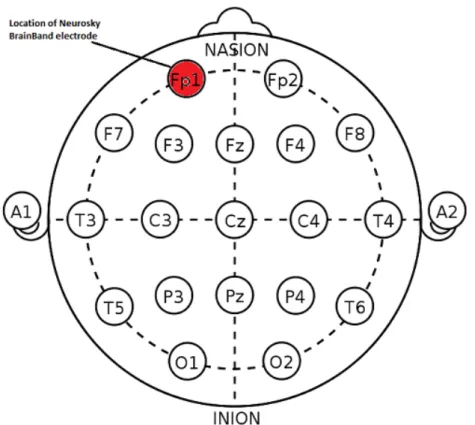
The placement of electrodes , dry or wet, on the scalp is done Explanation of the 10-20 system conventions based on an international method called the 10-20 system.
The naming comes from the percentage distance between the location of electrodes, 10% or 20% of inter-electrode distance. Each electrode location on the scalp in the system has a name composed of a letter representing the underlying brain lobe, and a number distinguishing the right and left brain hemispheres. The possible letters areF for Frontal,T for Temporal,P for parietal,Ofor Occipital andCfor Central which is not a lobe, but only used for identification purposes.
Even numbers refer to locations on the right hemisphere, whereas odd numbers refer to locations on the left brain
hemisphere. The area identified as the scalp starts from the ’Nasion’, which is the point between the forehead and the nose, and ends at the ’Inion’, which is identified as a bump at the end of the skull [Inc.,2001].
After acquiring the generated electrical potential via wet or dry electrodes, the signal has to undergo several stages of processing before being able to extract useful informa-tion out of it. There are 3 main stages which are: signal preprocessing, feature extraction and selection, and finally classification. An overview of those 3 stages is given in the following sections.
30 4 BCI Systems
Figure 4.2:10-20 Electrode Placement System : The location of the Neurosky elec-trode used in the work described in this thesis, Fp1 (Frontal polar - left hemisphere) is highlighted in red
4.2
EEG Signal Processing
Since the signal captured from the electrodes, dry or wet, EEG signals are very
weak hence have to be amplified via a biosignal amplifier
is typically in the order of microvolts or even nanovolts at times, it first has to pass through an amplifier to bring it to a stuiable range for processing. EEG devices used in this project had an embedded amplification circuit, hence no manual amplification needed to be done.
4.2.1 Noise and Artifact removal
After the signal amplification step of the preprocessing stage comes the noise and artifact removal step. EEG recordings are often noisy due to being very weak signals and due to noise coming from the environment in which the recording
4.2 EEG Signal Processing 31
was done. The main goal of this phase is to improve the quality of the captured signal by enhancing the Signal to Noise ratio. Smaller SNR means a noisier signal and a higher effort on the classification and feature extraction stage of the signal filtering [Graimann et al.,2011].
Noise and artifacts in the signal can be generated from Physiological artifacts include sweating and muscle movements a number of sources which can be broadly divided into
physiological and non-physiological sources. Physiological sources of artifacts include artifacts from muscle movements (Electromyographic (EMG) artifacts) , as well as artifacts from sweating which tamper with the impudence of the elec-trodes [Graimann et al.,2011]. Physiological artifacts from eye movements or blinking are called Electrocularographic artifacts (EOG). Figure 4.3 shows an EEG signal containing peaks from an EOG blinking artifact, removed using an adaptive filtering technique in the bottom figures. Potentials related to cardiac activity (Electrocardiogram (ECG) pulses) can also be seen in electrodes placed on the left side of the brain on pulsating vessels. This can be especially noted in overweight subjects.
Non-physiologic artifacts usually come from either faulty Non-physiological artifacts include electric equipment interference and wrong positioning equipment or from the 50 Hz interference from electric
equip-ment and cables in the surrounding environequip-ment [NeuroSky,
2009]. Another source of noise can occur from any slight de-tachment or misplacement of the electrodes from the user’s head. As a result, the potential difference rises to infinity, or saturates at a maximum, and then may fall back to zero. Such an artifact, however, can be easily detected in the EEG signal and rectified. This type of artifact has been encoun-tered in the work presented in this thesis and will be illus-trated and discussed in further chapters.
Due to those two types of artifacts most BCI user experi-ments were carried out in quiet and strictly monitored lab environments. Moving BCIs outside the lab and to the real world is considered a paradigm shift that would open many possibilities for using BCI systems in the day to day life of both healthy and handicapped users.
The removal of artifacts from the EEG signal is the first Artifact removal in offline and online studies without corrupting the signal is a complex procedure step in the long process of EEG signal processing. The
sim-32 4 BCI Systems
Figure 4.3:Top: EEG signal contaminated with EOG blinking artifacts - Middle & Bottom: Adaptive Filtering to remove EOG artifact [Correa and Leber,2011]
plest way to remove artifacts would be to discard the whole corrupt trial. This trivial way can only be used in the case of data collection for training during offline studies. How-ever, in case of online single-trial studies, the isolation and removal of artifacts has to be done without corrupting the underlying the EEG signal.
Principal Component Analysis (PCA) and Independent Component Analysis (ICA)
In case of EOG, EMG, and ECG artifacts, several time and Higher-order
statistical separation methods are used for artifact removal
frequency domain filtering methods can be used to detect and remove the artifact from the EEG signal. In addition, notch filters can be used to detect and remove the 50 Hz power artifact. The problem of those basic filtering methods is that they often smear of add even additional noise to the signal. Other higher-order statistical separation methods like Principal Component Analysis (PCA) and Independent
4.2 EEG Signal Processing 33
Component Analysis (ICA) are more efficient and more popular with more complex BCI systems involving a large number of electrodes (typically ¿ 32) [Smith,2004].
Principal component analysis (PCA) is a Blind Source PCA and ICA are two popular methods for artifact removal in multi-channel EEG signals
Separation (BSS) method that decomposes an EEG signal recorded from multiple electrodes into a set of linearly un-correlated components. As discussed inSmith[2004], the components comprising artifacts such as EOG or ECG can be either manually discarded in the recomposition or corre-lated with artifacts recorded from simultaneous trials and hence detected and removed.
Independent Component Analysis (ICA) is an extension of PCA. It is developed to deal with what is known as the ’Cocktail Party Problem’ defined in the definition box below.
As defined inFatourechi et al.[2007], ICA is a method of BSS which separates a mix independent source signals by forcing the components to be independent. It has proved highly successful in removing ocular artifacts (EOG). An advantage of of ICA is that it does not rely on the availability of reference artifacts for separating the noise signal from the EEG. On the other hand, it usually needs prior visual inspection to identify artifact components. Research on automating this process has been also proposed. ICA is also considered to be a computationally expensive task that is not well suited for online studies.
COCKTAILPARTYPROBLEM:
This problem occurs when a number of people are talking simultaneously in a room and one is trying to follow one of the discussions. This sort of auditory source separation problem can be smoothly handled by the human brain, however, it presents a complex problem in the world of digital signal processing.
Definition:
Cocktail Party Problem
PCA, ICA and frequency domain filtering are of course not the only artifact isolation and removal techniques available. A lot of research is concerned solely with this complex task, however, this report only aims to give a quick overview about this aspect.
34 4 BCI Systems
4.3
EEG Feature Extraction
After isolating and removing noise and artifacts and rectify-ing the EEG signal, the extraction of important and useful features from the EEG signal follows. Feature extraction intends to identify and extract specific characteristics of the EEG signal which encode the commands, messages, or brain activity during performing certain tasks. A variety of different feature extraction methods exist. Some of which extract time domain information, like the evoked potential amplitudes, whereas other information can be extracted by transforming the signal into the frequency domain [Cabrera,
2009]. The goal of this stage is to maximize the discrimina-tive information and therefore to optimally prepare the data for the subsequent classification step.
Section 3.2.1 explained the existence of several frequency do-Frequency domain
feature extraction via FFT is popular in EEG research
main bands in the EEG signal and illustrated their meanings. The existence of those frequency bands naturally motivates investigating the spectral EEG characteristics through apply-ing frequency domain transformation of the time domain digitized EEG signal. The power of the various frequency bands (delta, alpha, beta, theta and gamma) can be extracted and distinguished by using band pass filtering and Fast Fourier Transform (FFT).
In some recent studies includingOthman et al.[2009] and Cepstral coefficients
have recently been used in research as EEG features
Temko et al.[2010] , cepstral coefficients, which were origi-nally used for Automatic Speech Recognition (ASR) to ex-tract features from speech, were suggested for EEGs. A cepstrum is calculated by taking the result of a Fourier Trans-form (FT) of the logarithm of the spectrum of a signal. The power cepstrum particularily is popular is ASR and is de-fined by equation 4.1. P ower Cepstrum(x) = F n log(|F {f(t)}|2)o 2 (4.1)
The cepstrum is then converted to the Mel-scale, derived by
Stevens et al.[1937], which is a perceptual scale of pitches judged by listeners to be equal in distance from one another.
4.3 EEG Feature Extraction 35
Mel-frequency cepstral coefficients (MFCCs) are coefficients that collectively make up a Mel frequency cepstrum (MFC). Cepstral coefficients are also used as features in the work done in this thesis. The details of cepstral features extracted will be further discussed in chapter 6.
Among the features extracted from the time domain signal HJorth parameters proved successful in emotion recognition via EEGs
and used in the work in this thesis are the HJorth parameters which were derived byHjorth[1970]. They have been used in many works includingAnsari-Asl et al.[2007] and proved to be successful in EEG classification especially in the field of emotion recognition. There are three main parameters, signal activity, mobility and complexity which are explained by equations 4.2, 4.3 and 4.4. The HJorth activity refers to the variance of the signal whereas the signal mobility calculates the signal’s mean frequency where x’ stands for the derivative of signal x. Finally, Complexity measures the deviation of the signal from the sine shape.
Activity(x) = N P n−1 (x(n)−x¯) N (4.2) M obility(x) = s var(x0) var(x) (4.3) Complexity(x) = M obility(x 0) M obility(x) (4.4)
Although frequency domain features have proven more More time domain features can be extracted from EEGs such as RMS descriptive of EEG signals, some time domain features are
also used in classification. Those include the maximum and minimum signal values, root-mean-square (RMS) of the signal, phase coherence, and the differences or ratios between different electrode channels. The features used in this project will be explained in chapter 6 in details.
36 4 BCI Systems
4.3.1 Dimensionality Reduction (Feature Selec-tion)
Whereas feature extraction itself is considered a method of dimensionality reduction, in the sense that meaningful features better simplify and describe a dataset, extracting a very large number of features also requires a selection step to produce a subset of the best features describing the dataset.
Three main feature selection methods exist, namely : Fil-Wrappers, Filters, and
Embedded Feature Selection Algorithms
ters, Wrappers and Embedded. The filter feature selection method aims tofilter the attribute set to produce the most promising subset before learning commences. On the other hand, the wrapper methodwraps the learning algorithm into the selection procedure, which makes it computation-ally more expensiveWitten et al. [2011]. Finally, the em-bedded method, where the feature selection and induction processes , i.e. the process of learning the appropriate clas-sifier, are indivisible from each other [Mill´an et al.,2002]. The two feature selection filter methods that are used in this project are the correlation-based and information gain feature selection methods.
Correlation Based Feature Selection (CFS)
CFS is a relatively simplistic and fast feature subset selection method. It was first developed byHall[1999] who defined thebestsubset of features selected from a feature space to be:
Good feature subsets contain features highly cor-related with the classification, yet uncorcor-related to each other
The algorithm takes into consideration two criteria: There are two criteria
for choosing feature subsets
1. How good the individual features are at predicting the class
4.3 EEG Feature Extraction 37
2. How much the individual features correlate with the other features
Good subsets of features contain features that are highly cor- Highly correlated subsets are the chosen ones related with the class and uncorrelated with each other. CFS
is suitable for handling EEG data because it directly handles correlated and irrelevant features according toKoprinska
[2010].
Information Gain Feature Selection
Information Gain (IG) feature selection is a very popular and successful feature selection algorithm for highly dimen-sional data. IG is widely used in the area of Natural Lan-guage Processing (NLP) in text classification tasks [Yang and Pedersen,1997].
Given a set of classesC ={c1, . . . , ck}, the information gain of a featuref, defined asIG(f), is the expected reduction in entropyHcaused by observingf:
IG(f) =H(C)−H(C|F),where H(C) =− k X i=1 P(ci) logP(ci), H(C|F) =−P(f) k X i=1 P(ci|f) log P(ci|f) (4.5)
As explained inKoprinska[2010], the computation of the Selection of features is based on highest IG values
information gain is done for each feature across all classes and then the features are ranked based on their IG value. Features with a higher IG value are more informative. A sub-set containing a user-defined number of the highest ranked features is then chosen before moving to the classification step.
38 4 BCI Systems
4.4
EEG Signal Classification
This section explains the theoretical and mathematical back-ground behind some of the most popular classification tech-niques used in EEG signal classification. In the next chapter, Related Work 5, research done on EEGs using the discussed classification techniques will be overviewed as well.
4.4.1 Na¨ıve Bayes Classifier
Na¨ıve Bayes is a simple supervised learning probabilistic Naiive Bayes is
based on the rule of conditional probability
algorithm which assumes that the effect of an attribute value on a given class is independent of the values of the other attributes [Witten et al.,2011]. This na¨ıve assumption pro-duces as simple model which often works surprisingly well. Na¨ıve Bayes method is based onP(c|F)according to Bayes Rule of conditional probability,P(c|F)of an instancef and a classcwhich is given by:
P(c|F) =P(c)·P(F|c)
P(F) (4.6)
WhereP(c)is the probability of classcandP(F|c)is the Theoretical
explanation of Naiive Bayes
probability of instance F given class c. Having a set of training instances each consisting of a set of featuresF =
f1, f2, . . . , fk, then the probabilityP(F|c)can be given by the
multiplication of the probabilities of each individual feature
fkgiven the classc. Note that the denominator of equation 4.6 can be neglected by normalizing the probabilities of all attributes adding up to 1. Equation 4.6 can now be given as:
P(F|c) =P(f1, f2, . . . , fk|c)
=P(f1|c)·P(f2|c)·P(f3|c)·. . .·P(fk|c)
=Πf FP(f|c)
(4.7)
Finally, the probabilityP(c)of a classccan be computed as the frequency of occurance ofcin the training set.
4.4 EEG Signal Classification 39
Learning with the naive Bayes classifier is straightforward Na¨ıve Bayes assigns the instance to the class with the highest probability
and involves simply estimating the probabilities in the right side of Equation 4.6 from the training instances. The result is a probabilistic summary for each of the possible classes where the instance is assigned the class with the highest probability [Hall,1999].
4.4.2 Bayesian Network
To overcome the disadvantages of the Na¨ıve Bayes classi-fier and produce a classification technique more suited to real life problems in which attributes are actually depen-dent, Bayesian Networks were derived. Bayesian Networks intend to produce predictions of classes instead of only prob-abilities.
Bayesian Networks are a theoretically well-founded way of Graphical Representation of Bayesian Networks representing probability distributions concisely and
compre-hensibly in a graphical manner. They are represented as a network of nodes, one for each attribute, connected by di-rected edges in such a way that there are no cycles, which in graph theory is called adirected acyclic graph [Witten et al.,
2011]. Figure 4.4 represents a simple Bayesian Network.
4.4.3 Decision Trees
As defined inWitten et al.[2011], decision Trees represent Basic description of the nodes and leaves of a decision tree adivide-and-conquerapproach to the problem of learning.
Each node of the tree corresponds to a feature and each outgoing edge to a node at the next level is associated with a possible value or range of values of that feature whereas the tree leaf specifies the expected value of the class.
In a good decision tree, each node should be represent Characteristics of decision trees and their advantages the most informative feature among the features not yet
considered in the path from the root. This can be achieved by calculating the information gain (i.e. Entropy) due to that attribute [Mill´an et al.,2002]. On main advantage of using decision trees in classification is their simplicity. They do not require pruning of many parameters unlike other
40 4 BCI Systems Play Outlook Temperature Windy Humidity play yes no .633 .367 windy false true .350 .650 .583 .417 outlook
sunny overcast rainy .238 . 429 .333 .538 .077 .385 play yes no humidity high normal .350 .650 .750 .250 temperature
hot mild cool .238 . 429 .333 .385 .385 .231 play yes no play yes no play yes no
Figure 4.4: A simple Bayesian Network representing weather data [Witten et al.,
2011]
classification methods such as Artificial Neural Networks (ANNs). However, the decision tree used in this project, has two parameters which can be set: confidence value
and aminimum number of instances for pruning. Figure 4.5 represents a simple example of decision tree with the leaves representing the two available classesPlay orDon’t Playdepending on weather conditions represented in the different nodes with values on the edges.
4.4.4 Further Classification Methods
Although the work in this thesis only uses Na¨ıve Bayes, Bayesian Networks and Decision Tress, it is notable to men-tion that there are other popular classificamen-tion methods often used in BCI systems. Those include Artificial Neural
Net-4.4 EEG Signal Classification 41
Figure 4.5:A simple decision tree: Leaves represent the 2 classesPlay orDon’t Play
referring to playing golf if the weather attributes, written on the edges, is good [Witten et al.,2011]
works (ANN) and Support Vector Machines (SVM).
An Artificial Neural Network (ANN) is a computational ANNs perform well in solving non-linear classifications model that is inspired by biology. The most popular ANN
architecture is the feed-forward Neural Network consisting of mainly of three types of layers:input layer, hidden layers and an output layer. This type of ANN is suitable for solving non-linear classification problems by abstractly emulating the structure and operation of the biological nervous system.
The ANN architecture most widely used in EEG classifica- Finding the number of hidden layers in an ANN can be done by trial and error tion is the Multilayer Perceptron Neural Network (MLPNN)
consisting of input and output layers and any arbitrary num-ber of hidden layers which can be determined by pruning the network according to the complexity of the problem. Good determination of the number of hidden layers is cru-cial to the performance of the network. Too few hidden layers would lead to poor classification, whereas to many hidden layers would lead to over-fitting and of course, an increased time complexity. The most popular approach of finding the suitable number of hidden layers is simply by
42 4 BCI Systems
Figure 4.6:An illustration of an Artificial Neural Network (ANN) [Hamzah S.,2011]
trial and error [Subasi and Erc¸elebi,2005].
The use of ANNs in EEG classification is very popular and some examples of work using ANNs will be discussed in the following chapter 5. Figure 4.6, shows the structure of feed forward ANN.
A Support Vector Machine (SVM) is linear modeling algo-SVMs try to find the
maximal margin separating different classes
rithm which intends to find a linear separation boundary between different class instances. This boundary must have a maximal margin and this leads realizing better general-izations using SVMs making them a popular classification method. SVMs can also be used for non linear modeling by transforming the space into a hyperplane to deal with more complex classification problems [Kuzovkin].
Figure 4.7 illustrates an SVM classifying two classes. As can A sample SVM
example is illustrated in 4.7
be seen in the figure, boundary B1 does not separate the two classes, whereas boundaries B2 and B3 do. However, the euclidean distance between B2 and the nearest instances of both classes is smaller than that of B3. Hence B3 is the chosen
4.5 Commercial BCI Devices 43
boundary. This simple idea of the SVM can be generalized and adapted to suit much more complex and non-linear problems. B1 B2 B3 X1 X2
Figure 4.7:An SVM with 2 classes. B1 does not separate the classes. B2 separates the 2 classes but with a smaller margin than B3
4.5
Commercial BCI Devices
As introduced earlier, the two main BCI devices available in the market are the EPOC device by Emotiv, and the Neu-roSky devices (MindSet, MindWave and Brainband). The two brands have spiked the attention of many researchers in various fields due to their relative ease of use, portability and affordability.
44 4 BCI Systems
Figure 4.8:Emotiv EPOC [Technologies,2012 (accessed October 19, 2012]
Whereas in this project the NeuroSky devices were used, The Emotiv EPOC
device uses 14 wet electrodes for brain sensing
it is also important to briefly introduce the Emotiv Epoc as well. The EPOC neuroheadset is made up of 14 saline
sen-sors that are positioned according to the 10-20 positioning system (Figure 4.2) and two reference electrodes. Although the EPOC wet electrodes need some set up time, the device offers high-resolution EEG signals. The Epoc also communi-cated wirelessly over a Bluetooth connection and includes a gyroscope for better positioning information for cursor and camera control [Emotiv].
A wide range of applications are developed for the EPOC including games, neurofeedback applications and emotion recognition applications. The Epoc can detect various facial expressions, levels of engagement, frustration, mediation, and excitement [Shirazi et al.]. The EPOC comes with a con-trol panel software for connecting the device to the computer as well as training the device to be able to recogn
![Figure 2.1: Semi-autonomous wheelchairs developed at the University of Bremen operating via EEG signals acquired from an electrode cap [Graimann et al., 2011]](https://thumb-us.123doks.com/thumbv2/123dok_us/859111.2609547/30.892.149.749.227.601/autonomous-wheelchairs-developed-university-operating-acquired-electrode-graimann.webp)
![Figure 3.1: The 4 Lobes of the Cerebral Cortex [Health- [Health-Page.org, Jun 2010]](https://thumb-us.123doks.com/thumbv2/123dok_us/859111.2609547/38.892.326.737.521.968/figure-lobes-cerebral-cortex-health-health-page-jun.webp)
![Figure 3.3: 3 examples of measuring electric potentials: EEG, ECog, and Intracrotical Recording [Graimann et al., 2011]](https://thumb-us.123doks.com/thumbv2/123dok_us/859111.2609547/40.892.324.748.646.909/figure-examples-measuring-electric-potentials-intracrotical-recording-graimann.webp)
![Figure 3.4: Raw EEG signal from 14 electrode locations on the y-axis [Campbell et al., 2010]](https://thumb-us.123doks.com/thumbv2/123dok_us/859111.2609547/41.892.171.565.646.947/figure-raw-eeg-signal-electrode-locations-axis-campbell.webp)
![Figure 3.5: The P300 Speller [Krusienski et al., 2006]](https://thumb-us.123doks.com/thumbv2/123dok_us/859111.2609547/44.892.372.696.244.560/figure-the-p-speller-krusienski-et-al.webp)
![Figure 4.1: An illustration of the components of a BCI system [Bhardwaj and Bhateja, 2006]](https://thumb-us.123doks.com/thumbv2/123dok_us/859111.2609547/46.892.154.748.227.722/figure-illustration-components-bci-bhardwaj-bhateja.webp)
![Figure 4.4: A simple Bayesian Network representing weather data [Witten et al., 2011]](https://thumb-us.123doks.com/thumbv2/123dok_us/859111.2609547/58.892.162.722.237.671/figure-simple-bayesian-network-representing-weather-data-witten.webp)
![Figure 4.6: An illustration of an Artificial Neural Network (ANN) [Hamzah S., 2011]](https://thumb-us.123doks.com/thumbv2/123dok_us/859111.2609547/60.892.226.667.264.624/figure-illustration-artificial-neural-network-ann-hamzah-s.webp)