Survivable Virtual Network Redesign and
Embedding in Cloud Data Center Networks
Yiheng Chen
A Thesis in
The Department of
Concordia Institute for Information Systems Engineering
Presented in Partial Fulfillment of the Requirements for the Degree of Master of Applied Science (Information System Security) at Concordia
University
Montreal, Quebec, Canada
February 2015
ABSTRACT
Survivable Virtual Network Redesign and Embedding in Cloud Data Center Networks
Yiheng Chen
Today, the cloud computing paradigm enables multiple virtualized services to co-exist on the same physical machine and share the same physical resources, hardware, as well as energy consumption expenses. To allow cloud customers migrate their services on to the cloud side, the Infrastructure Provider (InP) or cloud data centre operator provisions to its tenants virtual
networks (VNs) to host their services. Virtual Networks can be thought of as segmenting the physical network and its resources, and such VN requests (or tenants) need to be mapped onto the substrate network and provisioned with sufficient physical resources as per the users' requirements. With this emerging computing paradigm, cloud customers may demand to have highly reliable services for the hosted applications; however, failures often happen unexpectedly in data-centers, interrupting critical cloud services. Consequently, VN or cloud services are provisioned with redundant resources to achieve the demanded level of service reliability. To maintain a profitable operation of their network and resources, and thus achieve increased long term revenues, cloud network operators often rely on optimizing the mapping of reliable cloud services. Such problem is referred to as in the literature as "Survivable Virtual Network
Embedding (SVNE) '' problem. In this thesis, the survivable VN embedding problem is studied and a novel cost-efficient Survivable Virtual Network Redesign algorithm is carefully designed, presented, and evaluated. Subsequently, we distinguish between the communication services provided by the cloud provider and study the problem of survivable embedding of multicast services; we formally model the problem, and present two algorithms to reactively maintain multicast trees in cloud data centers upon failures.
Contents
List of Figures Abbreviationsiv
1 Introduction 1
1.1 Background and Motivation . . . 1
1.1.1 Problem Definitions. . . 4
1.1.2 Reasoning and Optimizations . . . 5
1.2 Thesis Organization. . . 7
2 Preliminaries and Related Work 8 2.1 Failure Senarios and Protection Methods . . . 8
2.1.1 Type of Failures . . . 8
2.1.2 Protection Methods . . . 9
2.2 Virtual Network Redesign and Embedding . . . 10
2.2.1 Related Work on Virtual Network Redesign and Embedding 11 2.2.2 Virtual Network Redesign Solutions and limitations . . . 14
2.2.3 Resource Sharing techniques . . . 16
2.3 Multicast Virtual Network . . . 19
3 Survivable Virtual Network Redesign and Embedding 22 3.1 Introduction . . . 22
3.2 Problem Definition . . . 25
3.3 The SVN Redesign Problem . . . 28
3.3.1 Limitations of Conventional VN Redesign Techniques . . . . 28
3.3.2 Illustrative Example . . . 31
3.4 Prognostic Redesign Approach (Pro-Red) : . . . 33
3.4.1 Theoretical Foundation . . . 33
3.4.2 Pro-Red Algorithm : . . . 36
3.5 The SVN Embedding . . . 41
3.6 Numerical Results. . . 44
3.7 Conclusion . . . 48
4 Post-Failure Restoration for Multicast Services in Data Center Networks 50 4.1 Introduction . . . 50 v
4.2 Network Model and Problem Description . . . 51
4.2.1 Network Model . . . 51
4.2.2 Understanding the impact of failure on MVNs . . . 54
4.2.3 The MVN Restoration Problem . . . 57
4.2.3.1 Problem Formulation. . . 57
4.2.3.2 Complexity Analysis . . . 60
4.3 Path-Convergence Method for finding a backup source . . . 61
4.4 Hop-to-Hop Terminal Finding Algorithm . . . 63
4.5 Numerical Results. . . 66
4.6 Conclusion . . . 68
5 Conclusion and Future Work 70 5.1 Conclusion . . . 70
5.2 Contributions . . . 71
5.3 Future Work . . . 72
Bibliography 74
List of Figures
1.1 Virtual Network Embedding Problem . . . 4
2.1 Failure in the Substrate Network . . . 9
2.2 Survivable Virual Network Redesign Schemes . . . 11
2.3 Resource Sharing techniques in SVN embedding phrase . . . 17
3.1 Substrate Network and Virtual Network Representation . . . 26
3.2 Designing and Embedding Reliable VNs . . . 29
3.3 Theoretical Foundation . . . 33
3.4 Designing Reliable VNs. . . 35
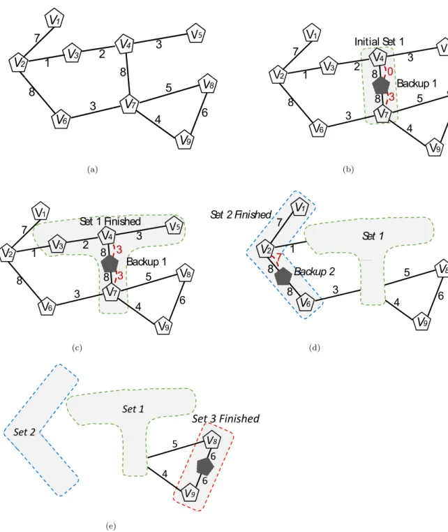
3.5 Step-by-Step SVN Redesign Algorithm. . . 40
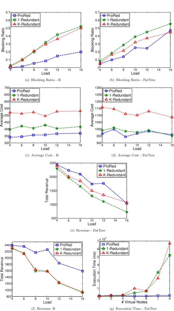
3.6 Comparison between Pro-Red, 1-Redundant and K-Redundant Scheme. 49 4.1 Network Model . . . 51
4.2 Impact of a Substrate Node or Physical Link Failure . . . 55
4.3 Muticast VN Maintenance Approaches Comparision Test Results . 69 5.1 Advantage of Terminal Nodes Migration . . . 73
Abbreviations
BG - Backup Group
DFS - Distribyted File-Systems
DVBMT - Delay- and Delay-Variation Bounded Multicast Tree FDP - Failure Dependent Protection
FIP - Failure Independent Protection HPC - High Performance Computing IaaS - Infrastructure as a Service InP - Infrastructure Provider MVN - Multicast Virtual Network
NP-hard - Non-deterministic Polynomial-time hard PaaS - Platform as a Service
QoS - Quality of Service SaaS - Software as a Service SDN - Software Define Network SLA - Service Level Agreement
SMVN - Survivable Multicast Virtual Network
SMVNE - Survivable Multicast Virtual Network Embedding SP - Service Provider
SVN - Survivable Virtual Network VDC - Virtual Data Center
VL - Virtual Link VM - Virtual Machine VN - Virtual Network
WG - Working Group
Chapter 1
Introduction
1.1
Background and Motivation
The Internet has made significant impact on our society, business models and our daily lives. As a new paradigm for the future Internet, cloud computing has drawn the attention of the general public in recent years. In simple terms, cloud com-puting is capable to create a virtual environment which allows both software and hardware to be shared by multiple-users via the Internet. With cloud computing, businesses are no longer required to incur investment on purchasing hardware and software licenses in order to deploy their services and applications. Moreover, hu-man expenses can also be reduced since the operating and maintaining cost will be shifted to the cloud side [1].
Today, there are two main players in the cloud computing market; namely, the Service Provider (SP) and the Infrastructure Provider (InP). The former allows cloud users access to the cloud service via the Internet; whereas, the latter man-ages infrastructures and leases physical resources to SP [2]. According to the type of services, cloud service scenarios can be classified into three main types: Infras-tructure as a Service (IaaS), in which the InPs split their resources and outsource
them to the SPs; for instance Amazon EC2 and Microsoft Azure are the appli-cations that would provide such service. Platform as a Service (PaaS), it offers a framework which systems users can build on, such as Google Apps Engine [2]. Last but not least, Software as a service (SaaS); instead of purchasing applica-tions running them locally, SaaS allows a software to be shared among users via the Internet; an example is GRIDS Lab Aneka[3]. In this thesis, a role of InP is assumed, and IaaS services, precisely Virtual Network (VN) service, are served to SPs based on their demands.
The InP provides an environment that allows Virtual Machines(VM) coexist on the same physical machine. Through a VMs management software “Hypervisor”, the InP is able to create, run and allocate resources for VMs. By sharing infras-tructures, the operating cost and hardware investment can be greatly reduced. VMs demand a minimum level of hardware specifications, typically in terms of CPU capacity, memory, disk space, etc. In order to host multiple VMs in one server, the server has to have sufficient physical resources. We address the VM placement action as “Virtual Machine Embedding”. In addition, cloud customers may migrate their network services to the cloud, thus Virtual Networks(VNs) need to be embedded with more requirements on bandwidth, delay and so on. Hence, the placement of VN becomes critical as good mapping solutions may cost less and result in better service admissibility in a data center. Accordingly, it is important for cloud vendors to optimize the placement of services to improve their revenue. The optimal placement of cloud services, referred as “Virtual Network Embedding (VNE)”, is known to be -Hard [4].
Now, cloud users may deploy certain critical services on the resources they leased, but the hosting servers may break down for a variety of reasons. When they do ,VNs would get disconnected and the services would be disrupted. Hence, it is very important for cloud vendors to provide certain degree of reliability to their hosted VNs in the datacenter. In fact, most of the major cloud sevice provider gaurantee their customers a certain level of QoS (Quality of Service), donoted as
“Service Level Agreement (SLA)”[5]. For example, Microsoft Azure promises its users 99.9% availability of their virtualized services. To obtain such highly reli-able service level, certain level of resource redundancy is required. The problem of embedding a virtualized service with reliability is referred as “Survivable Vir-tual Network Embedding (SVNE)”. There are two common failure scenarios in a cloud datacenter: Substrate node failure and substrate link failure. In both cases, redundancy needs to be provided in order to restore the failed services. Similar to working resources, the redundant resources also need to be mapped onto the substrate network, either before or after a failure; we call former“proactive protec-tion”, as it reserves resources to be ready for for future failures; and we refer the latter“reactive restoration”, since it finds alternative mapping solutions to restore the VN services after a failure. Indeed, the mapping of redundant resources would complicate the problem.
There are many SVNE solutions proposed by recent research papers; depending on the failures considered, some work focus on the failure of physical links[6–9], whereas others tackle the problem of node failures[10–17]; In this thesis, only fa-cility node (servers for example) failures are considered, the reasons are two folds: On one hand, link failures have been addressed in plenty of literatures, and the techniques introduced can be reused in the light of network virtualization; On the other hand, node failures effect the virtualized services running on the failed server directly, thus triggering VM migration to re-place those VMs and the correspond-ing virtual links must be re-mapped to resume the service. This is a variation of VNE problem, thus it is also considered to be NP-hard. Moreover, some work have been done to solve the SVNE problem in case of facility node failures in the substrate network. In [10, 16, 18–22] node mapping and link mapping meth-ods are developed for embedding a reliable-virtual-network, the resource sharing techniques are explored to reduce the cost for embedding redundant resources. However, in those work, redesigning survivable virtual network has never received enough attention; though in [11] [12], backup resources are augmented only when the overall availability does not meet the requirement, nonetheless cost efficient
is never considered for SVN redesign. Therefore, a technique is needed to design VN requests, taking sharing of resources into account, and output a survivable VN that can be embedded with least cost. In the first part of the thesis, a cost-efficient-oriented survivable virtual network redesign algorithm is proposed, which designs a VN request at virtual level, considering the future resource sharing in the embedding phase. In the second part of this thesis, we address the problem of Multicast Virtual Network (MVN) failures, and a novel reactive protection method is developed to protect the embeded MVNs from node failures.
1.1.1
Problem Definitions
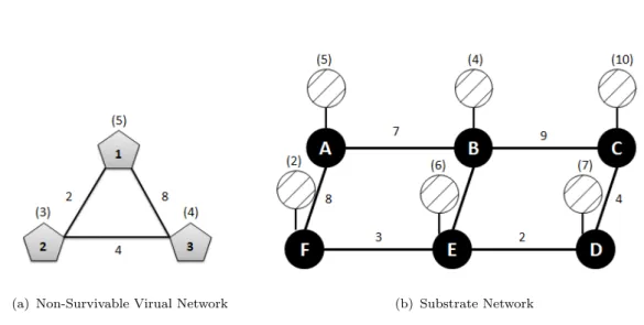
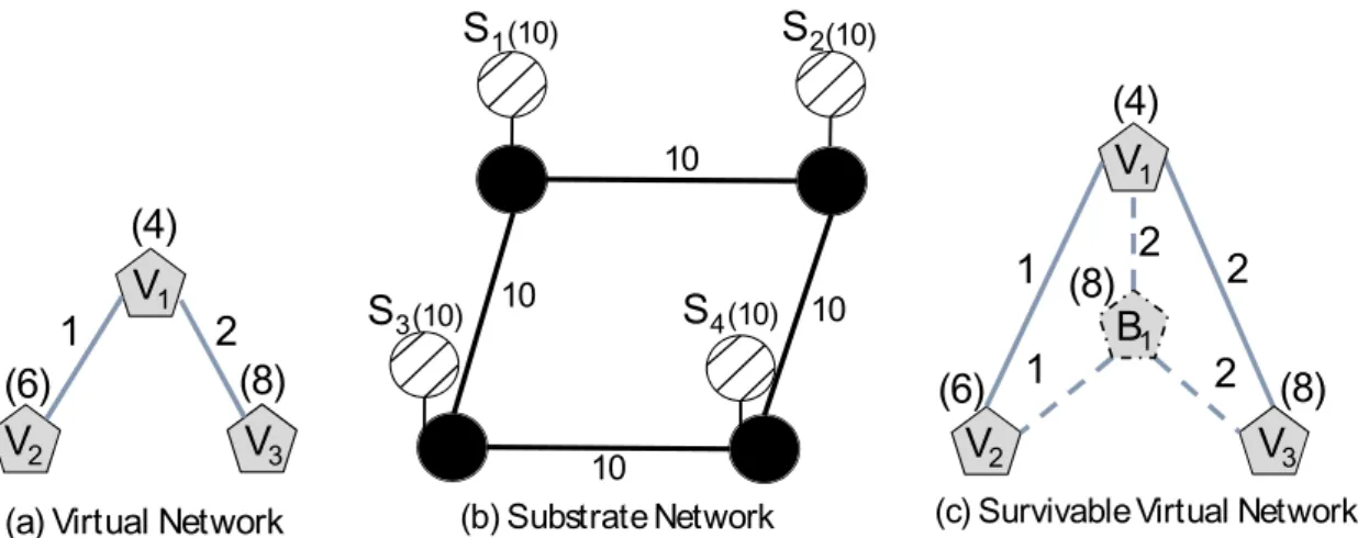
(a) Non-Survivable Virual Network (b) Substrate Network
Figure 1.1: Virtual Network Embedding Problem
The Substrate Network : We represent the substrate network as an undirected graph denoted by Gs = (N,L), where N is the set of substrate facility nodes, and
L is the set of substrate links. Facility nodes are connected to the network via network nodes (routers/switches). Each substrate facility noden∈N is associated with a finite computing capacity, denoted by cn. Similarly, each substrate link l ∈ L has a finite bandwidth capacity, denoted by dl. Figure 1.1(b) illustrates a
substrate network with 6 facility nodes, each with a CPU capacity varying from 2-10 units (represented by the number in parenthesis above each facility node). Similarly, bandwidth on the substrate links interconnecting the network nodes
exhibit a range from 2 to 9 units of bandwidth on each (represented by the number in parenthesis above each substrate link).
The Virtual Network (VN) : A Virtual network represents a client’s request to deploy an application in a cloud data center. It consists of a set of virtual nodes (virtual machines), interconnected with virtual links. The virtual links correspond to the communication requirements between the virtual nodes in a given VN re-quest. We denote a VN as a graph Gv = (V,E), where V represents the set of
virtual nodes, each with a CPU demand of cv, and e is the set of virtual links,
each with a bandwidth demand of de. Figure 1.1(a) shows an example of a VN
request with 3 virtual nodes and links, in addition to their associated CPU and bandwidth demands, respectively.
Given the VN request, the VNE problem aims to map this request onto the sub-strate network while providing enough resource as demanded. On one hand, each substrate element has independent capacity; on the other hand, each VN request has specific resource requirement[23]. Hence, the problem is to find a minimal cost solution for each VN request. The formal definition of virtual network embedding is described as follows:
Problem Definition 1. Given a substrate networkGs = (N, L), and a VN request
Gv = (V,E). Find the optimal embedding solution of Gv = (V,E), such that cost
of resources spent in the substrate network is minimized, while guaranteeing the capacity on the substrate network elements are not violated.
1.1.2
Reasoning and Optimizations
Many research work has been done to solve the VNE problem presented above. As this problem is proven to be N P −hard[4] , much research focuses on developing heuristic and meta-heuristic methods and solutions [23]. With these VNE tech-niques, the mapping of VN requests should be able to obtain low-cost solutions, and thus yield higher VN requests admission. Consequently, the long term revenue
is increased for InP, and the rental cost for VN customers can be lowered.
Today, most cloud vendors guarantee their users with high level of service avail-ability; for instance, services that are hosted on Amazon EC2 are promised to have 99.95 % availability; users can get 10% - 30% of their service credits back, if the reliability level of their virtual services are violated. To achieve such high level of service survivability, resource redundancy to virtualized services need to be deployed at provisioning time or post-failure. On one hand, InPs are required to deliver highly reliable VNs, thus redundancy must be deployed; on the other hand, without a proper embedding technique, such redundancy may not be cost-efficient [24]. Such problem is known as “Survivable Virtual Network Embedding”. As SVNE problem can be divided into primary resource embedding and backup re-source embedding, and the former alone is aN P−hardproblem (virtual network embedding problem), thus survivable virtual network embedding problem is even harder to solve.
Numerous research work have attemptted to address the SVNE problem. Similar to the VNE problem, most of the work relax it by solving the embedding in more than one step. Moreover, mathmetical models [10–12, 16, 18–22] proposed but most of them are either not scalable or non-linear. Consequently, heuristics[10,
12,16, 18, 20] are introduced and acceptable solutions can be achieved.
In this thesis, we make two main contributions on SVNE problem, and are sum-marized as the following:
• A cost-efficient SVN redesign algorithm is proposed to solve the survivable VN redesign problem, and a mathmetical model is presented to embed a given SVN assuming single facility node failures.
• We consider multicast cloud services and in particular present embedding and maintenance techniques when such services are hosted by a cloud data center.
1.2
Thesis Organization
The rest of this thesis is organized as follows. In Chapter 2, related background knowledge are introduced; specifically, the type of failures in the cloud datacenter, and corresponding protection methods. Also, each processing stage in SVNE is discussed in this Chapter. The characterization of VNs are discussed at the end of this Chapter. Chapter 3 studied the survivable VN redesign taking the sharing techniques into account, a novel design method is proposed and compared against conventional redesign schemes. Multicast virtual network is being considered in Chapter 4, two multicast-tree maintance algorithms are designed to reactively restore multicast VNs from node failures, while ensuring the delay constraints are satisfied. Finally, conclusion and future work are presented in Chapter 5.
Chapter 2
Preliminaries and Related Work
2.1
Failure Senarios and Protection Methods
Fault-tolerance is a major concern of datacenter operators[25]. To protect virtu-alized services from failures, failure senarios must be studied as well as the com-monly deloyed countermeasures. In this subsection, the related work and recent researches are surveyed.
2.1.1
Type of Failures
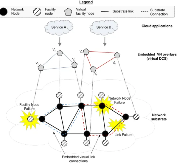
Both substrate links and substrate nodes may fail, and all virtualized services that are running on top of them would be interupted. If a physical server fails, all VMs that are being hosted on it will be shut down. Figure.2.1 illustrates how a facility node (server) failure will affect the Virtual Machine (V1) running on top
of it. Similarly, the disconnection of a physical link may suspend all virtual links that traverse through it. As shown in Fig.2.1, the physical link failure disconnects the communication between VM V5 and V6. Therefore, we classify the substrate
failures as ”Link Failure” and ”Node Failure”, where the latter can be further subdivided as ”Network Node Failure” and ”Facility Node Failure”[18]. ”Network Nodes” usually refer to networking devices such as routers, switches, whereas
V1 V2 V3 V4 V6 V5 Facility Node Failure
Embedded virtual link connections Network substrate Cloud applications Service A Service B Embedded VN overlays (virtual DCS) Network Node Failure Link Failure Network Node Virtual facility node Facility node Legend
Substrate link Substrate Connection
Figure 2.1: Failure in the Substrate Network
”Facility Nodes” refer to servers that host virtual machines. In Fig.2.1, a failure of a network node would terminate all the comunications which traverse through. In terms of the scale of failures, there are ”Regional Failure”[26], which effect multiple substrate elements, including nodes and links, at a time; and ”Signle Failure”, which means only one substrate element outage, it can be either signle server break down or single link disconnection. In this thesis, only a single facility node failure is assumed.
2.1.2
Protection Methods
There are two main types of failure countermeasures, namely P rotection and Restoration[27]. Protection reserves backup resources proactively, the redundant
backup resources are always assigned before actual failure. These resources would keep inactive until failure happens. On the other hand, restoration protects VNs in a reactive manner. It is only activate after failure happens, and it is called on demand to search for alternative mapping solution for the failed element(s). In reactive approach, there is no redundancy provided, therefore, the embedding cost of VNs that are running reactive restoration is definitely less than it of VNs assigned with redundancy, hence it may allow substrate network to admit more VN requests. However, upon failures, reactive approach does not gaurantee 100% recovery of disrupted VNs, as it may not be able to find a feasible solution; whereas proactively protected VNs can always be reconnected.
In terms of post-failure recovery capability, there are Failure Dependent Protec-tion (FDP)[28, 29] and Failure Independent Protection (FIP)[10, 19–22]. In FIP, each primary node will be assigned a specific backup node, such that upon failure occurence, the primary can only be migrated to that backup host. In compari-son, FDP allows working hosts to have different backup hosts in different failure scenarios, and sometimes even working nodes are allowed to migrate [14]. In this thesis, only FIP methods are considered.
2.2
Virtual Network Redesign and Embedding
In a typical Survivable Virtual Network Embedding solution, two design stages are performed, namely ”reliable virtual network redesign” and ”survivable virtual network embedding”. In the redesign stage, a given Virtual Network would be augmented with redundant computational and bandwidth resources, such that any facility node failure can be tolerated. The resulting graph is called ”Sur-vivable Virtual Network”, and sometimes it is referred to ”Sur”Sur-vivable Virtual Infrastructure”[16]. In the embedding stage, the reliable-virtual-network from the previous stage would be mapped onto the substrate network. While embed-ding, it is important to make sure that the resources are shared and total cost is minimized[18].
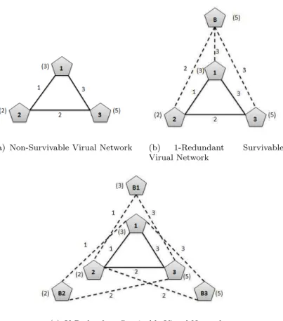
(a) Non-Survivable Virual Network (b) 1-Redundant Survivable Virual Network
(c) K-Redundant Survivable Virual Network
Figure 2.2: Survivable Virual Network Redesign Schemes
2.2.1
Related Work on Virtual Network Redesign and
Em-bedding
Many work in the literature has been devoted towards understanding and charac-terizing failure in cloud data center networks [24], [30]. From these studies, we can conclude that failure in data center networks can happen due to single or multi-ple network components failures (facility nodes, links, switches/routers), and the incurred financial losses are real. This means that the cloud provider must invest additional resources to mitigate substrate network failures, and fulfil the promises of reliability and availability to the hosted tenants’s applications and services. In [30], the authors focus on characterizing servers failure rate. The authors analyzed these failure characteristics using a real data center over the period of 14 months, and concluded that hard-disks are the most dominant reason behind server fail-ures, and that 8% of all servers in a data center are expected to fail within a year. Further, the authors have also looked at successive failure rates, meaning
the probability that a failed server would fail again after repair, and it was found that successive failure rates are quite high. For a 100 servers data center where 4 machines has failed more than once in 14 months; it was found that 20% of all repeat failures happen within a day of the first failure; while 50% happen within two weeks. Indeed, the estimated repair cost for a typical data center with more than 100,000 servers is estimated in millions of dollars; not to mention the incurred penalty cost due to affected services disruption.
In this regard, survivability against facility node failure is of paramount impor-tance, particularly in the case of critical services that don’t tolerate failure. Indeed, this problem has attracted significant attention from the literature; here we can distinguish between single facility node failure [16], [18], [14], [15], and multiple facility nodes failure [17], [13], [10]. In the case of single facility node failure, the authors of [18] introduce a two-step approach to fully restore a VN from any single facility node failure. Mainly, their approach consists of augmenting the VN request with a 1-redundant or k-redundant backup nodes (where k represent the number of critical nodes). The resultant SVN is then mapped onto the substrate network by placing virtual nodes in a given VN on distinct substrate nodes, while aiming to minimize the overall embedding cost. For this purpose, the authors introduce two backup-sharing techniques to minimize the incurred backup-bandwidth cost, namely cross-sharing and back-up sharing. The same problem is tackled in [16], here the authors consider the SVN to be given, and their aim is to map the SVN onto the substrate network while minimizing the amount of idle backup band-width. The virtual nodes in a given VN maybe be mapped on the same substrate nodes, as long as their corresponding backup nodes are mapped on distinct nodes; this guarantees survivability against any single facility node failure. To embed the SVN onto the substrate network, two embedding heuristics are presented: A disjoint and a coordinated virtual node and virtual link mapping. For the disjoint embedding approach, a set of feasible node mapping solutions is first enumerated, then this set is passed on to an ILP model that picks the node mapping solution with the lowest reserved backup bandwidth, while the coordinated embedding
adopts a link packing approach. Further, in [14], the authors present a novel ap-proach for redesigning an SVN, denoted as Enhanced VN (EVN), and distinguish between failure-dependent and failure-independent EVN. The failure-independent EVN is similar to the 1-redundant SVN, while the failure-dependent EVN aims at minimizing the amount of idle backup resources by relaxing the constraint that only failed nodes will migrate. Instead, for each different failure-event, virtual nodes (primaries and backups) within a given VN will be re-arranged (migrated) differently to resume a working VN. Note that such approach incurs a consider-able amount of migration overhead that can potentially cause a longer down-time. Moreover, in [15] the authors also adopt the 1-redundant SVN scheme to create an Auxiliary Protection Graph (APG). The APG is next embedded onto the substrate network using a tabu-search meta-heuristic with cross-sharing and backup-sharing to minimize the backup footprints.
As for survivability against multiple facility node failure [17], [13], [10], the VN is augmented with the minimum number of backup nodes needed to guarantee a reliability degreer under a given probability of failurep. Further, in [17] and [10], the authors employ sharing across VNs in order to circumvent the inconvenience of idle resources. As for [13], the authors employ survivability at the inter-data center level, where a local protection approach is introduced to eliminate backup bandwidth over wide-area network.
Equal effort has been devoted towards inaugurating effective protection schemes against substrate link failures [6], [22], [7], [21]. Here protection schemes can be mainly categorized as link-based and path-based protection. Further, few work in the literature tackled the case of correlated failure [31], [32], that is the case of single ”regional” failure that brings down multiple substrate nodes and links at the same time. Substrate nodes and links that fail together are also referred to as ”shared risk group”. Here risk groups are considered to be given and protection schemes are tailored for the case of a single risk group (regional) failure. A thor-ough taxonomy of the various failure scenarios and existing protection methods can be found in [33].
2.2.2
Virtual Network Redesign Solutions and limitations
Two redesign topologies are commonly deployed in the literature, namely 1-Redundant and K-Redundant.
A. 1-Redundant scheme[18]
In 1-Redundant scheme, one backup virtual machine is added to the original vir-tual network, connecting all primary virvir-tual nodes via backup virvir-tual links. When any of these primary virtual node fails, it migrates the redundant virtual machine through VM migration, and continue communicating with other virtual nodes us-ing the backup virtual links. Figure 2.2(a) shows an example of a VN request, which is consist of 3 VMs interconnected by virtual links. In Fig. 2.2(b), the given VN is redesigned using the 1-Redundant method, the virtual node B is the redundant virtual machine, and it is connecting virtual node 1, virtual node 2 and virtual node 3 via virtual backup link{B,1}, {B,2}and {B,3} respectively. As-sume a failure occured on virtual node 1, backup virtual nodeBwill then take over the role of virtual node 1, and establish connections with node 2 and 3 through link {B,2} and link {B,3}; as B, in this example, has to re-connect the service assuming any primary node can fail and thus it must be able to replace the failed VM, clearly node B has to be provisioned with the maximal amount of compu-tational resources among all the primary VMs; in this example backup node B has to reserve 5 units of CPU. Similarly, the amount of backup bandwidth which is required to be reserved on backup links also need to be calculated such that, when backup node is replacing the disconnected VM, the backup virtual links will have sufficient bandwidth to establish network connections with the neighbors of the disconnected VM. For example, when failure occures and bring down primary node 1, and B will be activated to replace node 1. To resume the communi-cations between B to 2 and B to 3, virtual backup link {B,2} and link {B,3}
must also have enough reserved bandwidth to replace primary link {1,2} and link
bandwidth amount of 1 and link {B,3} 3 units of bandwidth. However, in the case of node 3 failure, link {B,2} must have 2 units of bandwidth to recover the connection between node 2 and 1. Therefore, due to the fact that {B,2} will be activated when either node 1 or 3 fails, we assign this link a bandwidth demand of 2, which is the maximal among the bandwidth demand in both cases.
B. K-Redundant scheme[18]
In K-Redundant scheme, K (K equals to the number of critical nodes) in number of backup virtual machines which are added to the original virtual network; here, unlike the 1-Redundant scheme, in which a backup node connects to all primary virtual nodes, each backup node in K-Redundant only connects to the neighbors of the primary node it protects. In other words, each primary node is assigned a backup VM, and this backup VM also has virtual links connecting all its neigh-bors. Figure 2.2(c) shows an example of a K-Redundant design, where the given VN in Fig. 2.2(a) is provisioned with 3 backup nodes. B1, B2 and B3; they are assigned to replace VM 1, VM 2 and VM 3 respectively. As each backup node protects one primary VM only, the computational resource which needs to be reserved is equal to the CPU requirement of the corresponding primary VM, rather than the max of the CPU demand of all VMs as in the 1-Redundant. For example, in 2.2(c), backup node B1 only needs to reserve 3 units of CPU, as it
only protects node 1. Moreover, since backup nodes do not require to connect to all VMs, it is more flexible in the embedding phase. However, since more VMs are used in this solution, the amount of reserved CPU units will always be higher than 1-Redundant solution.
C. Current Redesign scheme Limitations
So far, research work that address the SNVE problem considering single node fail-ure always emphasise on the SVN mapping solutions, and pay less attention on
the survivable redesign phrase of VN requests. In fact, the SVN design is an im-portant factor that could decide the cost of a VN request. However, most existing literature simply apply either the 1-Redundant or the K-Redundant scheme.[16]. No research, however, has a clear SVN redesign method, that is able to specify the exact number (n, 1≤n ≤K) of backup nodes of a given VN should have and how are they connecting to the original VN in a cost-efficient way. In this thesis, an SVN redesign algorithm is introduced in Chapter 3, in order to address this issue.
2.2.3
Resource Sharing techniques
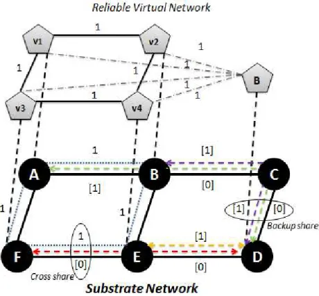
After provisioning VN requests with redundant resources at the VN level, the ob-tained SVN will be required to be embedded onto the substrate network. However, as redundant node(s) and link(s) are added to the VN, they may consume large amount of physical resources. As a consequence, the entire SVN may be rejected by the cloud operator, due to insufficient bandwidth and computational resource. Hence, it is very important to explore the opportunities of sharing backup re-sources, as a mean to increase the network availability. In fact, recent research[34] shows the data transfer and exchange between VMs count for 80 % of the total traffic in a data center. Thus, by sharing the bandwidth capacity between VMs, we may reduce the traffic congestion within a data center, and eventually boost the VN requests admission. In this subsection, two bandwidth sharing techniques are introduced.
A. Backup Sharing[18]
To explore bandwidth sharing, we first identify a working-group, denotes asW G(v) and a backup-group BG(v) for each VM v ∈ Nv. A working-group W G(v)
con-tains virtual links that are connecting VMv itself and its neighbors. For instance, in Figure 2.3, l{v1,v2} and l{v2,v4} are the working-group of virtual node v2. A
Figure 2.3: Resource Sharing techniques in SVN embedding phrase
be activiated after the failure of node v. They are usually connecting v’s backup VM and v’s neighbors [18]. In Fig. 2.3, the backup-group of VM v4 has link l{v2,B} and l{v3,B}. Upon the failure of v4, it migrates to VM B and continues
communicating withv2 andv3 via l{v2,B} and l{v3,B}.
Given the backup-group of each virtual node, it is obvious that links in different backup-groups will not be activiated at the same time, as we only consider single node failure. Hence, if the mapping of the virtual links in different backup-groups have common substrate links, the bandwidth resource reserved on that specific physical link can be shared, and only the maximal amount needs be allocated. In Figure2.3,l{v1,B} is inBG(v2) andBG(v3), whereas l{v1,B} can be in the
backup-group of v1 and v4. Therefore, those two virtual links will never be activated simultaneously, thus upon the link mapping, l{v1,B} and l{v2,B} pass through two
common substrate links l{D,C} and l{C,B}, on which the reserved bandwidth can
be shared. Therefore, we allocate only 1 unit of backup bandwidth on substrate linksl{D,C} andl{C,B}, whereas without sharing 2 units must be reserved on them.
We denote such type of sharing ”backup share”[18].
B. Cross Sharing[18]
Upon the failure of a facility node, the VM(s) running on top of this node will fail as well, and the communications between this VM and other VMs in the same vir-tual network are disconnected. As a result, there will be some bandwidth released from those disconnected communications which then can be reused by the backup virtual links, only if the disconnected virtual primary links are inW G(v) and the backup virtual links are in BG(v). For instance, in Figure 2.3, l{v3,v4} and l{v3,B}
are inW G(v4) andBG(v4) respectively, so the failure ofv4 will disconnectl{v3,v4},
which is mapped on substrate link l{E,F}; the amount of bandwidth reserved on it
will be released, and since l{v3,B} will be activated after the failure, the released
1 unit of bandwidth on substrate link l{E,F} can be reused by l{v3,B}, therefore,
there is no need to provision backup onl{E,F}. We classify such bandwidth sharing
stragegy as ”cross share”[18].
C. Current Resource Sharing Methods Limitations
In existing SVNE solutions, resources sharing normally happens in the embedding phase, and is encouraged throughout the whole process, in both node mapping and link mapping. To achieve optimal solution for the embedding problem, one must add both cross share and backup share as constraints to reduce the mapping cost. The mapping of both primary and backup resources would be decided with the objective of maximizing shared resources. This attempt puts the SVN embed-ding into an awkward position, as the SVN intends to be embedded in a way that the shared resources are maximized; on the other hand, the resources can only be shared once the mapping solution are given. This fact slows down the execution of the SVNE solutions. Therefore, the challenge is to find a time-efficient search technique that utilizes resources sharing as much as possible. Hence, a prognostic
SVN redesign technique ”ProRed” is proposed in this thesis, the highlight of this technique is its ability to consider the resource sharing while augmenting backup resources to the original VN, as if the redundant resources in the output SVN can ”predict” sharing at the virtual level. Consquently, upon the embedding phase, the sharing does not need to be involved, and solutions can be found rapidly.
2.3
Multicast Virtual Network
One-to-many communication is quite common in multiple applications and ser-vices hosted in cloud data center networks [35–41]. For instance, High Perfor-mance Computing1 (HPC) applications often need to distribute a large amount of data from storage to all compute nodes [39]. Web-search services are another ex-ample of multicast services that consist of redirecting incoming search-queries to a set of indexing servers [44]. Further, bandwidth-hungry Distributed File-Systems (DFS) are common data center applications [37], [45], [46]. DFS divides files into fixed-size chunks to be replicated and stored in different servers for reliability [35], [37]. Moreover, multicasting can be employed for the distribution of executable binaries among participating servers in map reduce-like cooperative computation systems [35], [36].
Services with a one-to-many communication mode can be easily treated as unicast by replicating the transmission to each receiver, or as broadcast by flooding the data throughout the network [47]. However, if the multicast of data is occurring in high volumes (e.g. HPC applications), then replacing these multiple unicast mes-sages by a single multicast message can incur great benefits in terms of reducing the computation efforts at the source node, greatly shrinking bandwidth consump-tion in the network, and subsequently increasing the applicaconsump-tion’s throughput and enhancing its response time. Similarly avoiding the use of broadcasting can al-leviate unnecessary processing to detect and reject irrelevant traffic from nodes
1HPC applications are conventionally employed in distributed parallel computers such as
supercomputers and grid-computing. However, the emergence of cloud computing has triggered significant attention around the possibilities of migrating HPCs to the cloud [42,43].
outside the multicast group. Hence, for network operators that host multicast services with heavy traffic, it is imperative to have efficient multicast support in their data center networks.
IP Multicast [48] is the traditional implementation of multicast in the Internet. However, this former suffers from many limitations which have inhibited its ubiq-uitous use. These limitations are mainly concerns of security, scalability, and flow control [49]; many of which have been alleviated and tackled in data center net-works owing to the emergence of Software Defined Netnet-works (SDNs) [49]. SDN provides a vantage point to network and applications information, allowing the detection and handle of diverse service classes with distinct QoS requirements (i.e. delay-sensitive multicast services). Further, it enables the support of multi-cast in commodity-switches that lack built-in support. This emerging networking paradigm has surpassed the mere potential to enable multicast in data center net-works, rendering a fertile ground to innovate and enhance its adoption.
To this extent, multicast in data center networks has become a prominent research topic [35, 37, 40, 41, 49–51], with particular attention to the resource allocation problem of MVNs [40, 41, 50, 51]. The former consists of allocating physical re-sources to the Virtual Machines (VMs) running a tenant’s service, and routing the traffic flow between them via substrate paths. In the case of a multicast ser-vice, this embedding problem differs from the classical (unicast) VNE problem in many aspects; mainly, a multicast VN comprises two types of virtual nodes (machines): the multicast source node and a set of multicast recipient nodes (ter-minals). The traffic flow routing now consists of building a multicast distribution tree between the multicast source and terminals in order to avoid redundant traffic. Also, multicast services that involve real-time communication entail stringent QoS requirements, such as end-delay and delay-variation constraints. Another QoS re-quirement that both unicast and multicast VNs share is a demand for reliability guarantees; that is a reassurance that the hosted service will remain up and run-ning despite any network component failure. Failure in the physical infrastructure is common due to a multitude of reasons [52] that can affect one or many network component. In fact, it can either attain a facility node (servers), a network node
(e.g. router/switch), or a substrate link.
Although the problem of survivable unicast VNs has been widely discussed [33], the impact of failure on multicast services differs in several aspects, which ulti-mately inhibit the applicability of existing unicast protection schemes. Indeed, in this case, restoring a failed service component is not solely restricted to find-ing a backup that matches the failed component’s resource demands, but also to connect this backup to the rest of the multicast service while satisfying its QoS requirements, and maintaining a low cost distribution tree. Therefore, this work is dedicated towards studying the problem of reliable MVNs in failure-prone data center networks, and propose a novel post-failure restoration scheme with tree maintenance. Our work is different from the relevant literature [40], since our proposed protection scheme capable of restoring MVNs against any single facility node or substrate link failure. Further, our tree maintenance component guaran-tees that the restored solution maintains a low cost tree that respects the delay constraints of the restored MVN services. Our numerical results prove that our suggested approach outperforms existing protection schemes in terms of achievable long-term revenue.
In Chapter 4, an effort has been put on embedded multicast virtual networks considering the case of single node failure.
Chapter 3
Survivable Virtual Network
Redesign and Embedding
3.1
Introduction
Network virtualization is a key enabler of the multi-tenancy concept [25], where multiple network architectures and services can run on top of the same physical infrastructure. With network virtualization, the problem of allocating resources to the various tenants emerges as a challenging problem. This problem is formally known as the Virtual Network Embedding problem (VNE), which is proven to be NP-Hard [4]; therefore, numerous efforts have been devoted towards inaugurat-ing effective heuristics for solvinaugurat-ing it [19, 20, 53–55]. The main weakness in these suggested approaches, in addition to the lack of a guarantee on the quality of the obtained solution, is that they assume that the physical infrastructure is available at all times, which renders most of the work in the area of VNE inapplicable in scenarios where network component failures can occur. Failures in the physical infrastructure are common due to a multitude of reasons [56]. In fact, the year 2013 has witnessed multiple cloud outages[57]; one of which got hold of the famous Amazon’s EC2 cloud, causing 5 million dollars in revenue loss for a single hour of
offline time. With millions of dollars at stake, attention converged towards solv-ing the Survivable Virtual Network Embeddsolv-ing problem (SVNE) [6,7,14–18, 31]. Given that the SVNE problem is a variation of the VNE problem, it is also NP-Hard. Hence, most of the relevant literature relax the problem by targeting one network component failure type: facility node failures, network node failures, or link failures, as illustrated in Figure 2.1. Some further simplify the problem by considering that a single network component can fail at any given point in time.
In this Chapter, we consider the case of single facility node failures. When a fa-cility node fails, the hosted virtual node(s) needs to migrate to a backup fafa-cility node, as well as its associated connections to other virtual nodes belonging to the same virtual network (VN). One way of achieving this failure recovery is by redesigning the VN request into a Survivable VN (SVN), and then mapping the resultant SVN onto the physical network. This redesign consists of augmenting the original VN with backup nodes. Each backup node is in charge of protecting one or many primary nodes. Hence, backup virtual links must be established between each backup node and the neighbors of the primary nodes it protects. Upon the failure of a facility node which hosts a virtual nodev,v will migrate to its associ-ated backup node, which will then resume the communication withv’s neighbors. The augmented backup virtual nodes and links need to be provisioned with suf-ficient computing and bandwidth capacity to recover from any facility node failure.
The survivable redesign technique encloses multiple challenges. Chief among these challenges is deciding how many backup nodes to use and how to allocate these backup nodes to the primary nodes in each VN such that we minimize the backup footprints in the substrate network. This problem is of paramount importance since these provisioned resources will remain idle until failures occur. Hence, over-provisioning can greatly impact the network’s ability to admit future requests. Indeed, the cost-efficient survivable redesign problem against single facility node failures has recurred multiple times in the literature [16], [18], [14], [15]. However, in all of the previous contributions, the number of backup nodes is fixed to either
1 or k, k being the number of critical nodes in a given VN. In addition, to cir-cumvent the inconvenience of idle resources, these latter introduce various backup resource sharing opportunities which can be exploited in the substrate network upon mapping the resultant SVN. In this Chapter, we argue that fixing the num-ber of backup nodes to either 1 or k could yield infeasible or even costly mapping solutions. We provide several motivational examples to support our proclama-tion. Moreover, we observe that all of the aforementioned redesign techniques are agnostic to the backup resource sharing in the substrate network, where this re-sponsibility is delegated to the adopted mapping algorithm. This is problematic, since given that the SVNE is NP-Hard[4], adding more constraints for backup resource sharing will surely yield a more complex model. Hence, the existing lit-erature solve this problem by relaxing the SVNE algorithm [6, 7, 14–18,31]. For instance, by solving the virtual node mapping and virtual link mapping disjointly [6], [16], [7], [17], [14], [15] or by performing the primary and backup mapping in a sequential fashion [6], [31], [18], [14]. Multiple other decomposition schemes can be applied; however, it is these very same relaxation techniques that sacrifice the quality of the obtained solution. This results in costly embedding solutions that are incapable of exploiting backup resource sharing in the substrate network, and lead to a substantial amount of backup idle resources that limit the cloud provider’s long term revenue.
In light of the above, we introduce Pro-Red; a novel prognostic redesign approach that explores the space between 1 and kand promotes backup resource sharing at the VN level. Hence, it alleviates this concern from the embedding algorithm and achieves cost-efficient SVNs using abridged mapping techniques. Pro-Red adopts a unique approach for the redesign; not only does it determine the augmented number of backup nodes and their connections to the primary nodes, but also their actual positioning in the VN such that it minimizes the provisioned cost at the substrate level. Hence, its prognostic property lays in its ability to foretell the backup resource sharing at the VN level, prior to the embedding phase. Our nu-merical results prove that our suggested approach yields significant gain in terms of increasing the substrate network’s admission rate, decreasing the amount of idle
bandwidth in the substrate network, and boosting the overall revenue of the cloud provider.
In this Chapter, we focus on the case of single facility node failure. Our work is different since mainly we prove that while existing techniques tend to fix the number of back-up nodes to either 1 ork, in this Chapter we present firm motiva-tional examples that prove that in many cases the 1 or k redundant schemes can yield infeasible or costly mapping solutions. Hence, we introduce a novel redesign technique that is capable of exploring the space between 1 and k. Further, while all of the existing work employs backup-sharing during the embedding phase, we swerve from this conventional approach and take the backup-sharing to the VN level by designing SVN with inherit back-sharing properties. This allows us to embed the SVN as a VN without the complication of backup-sharing concerns that surely yield a more complex mapping.
The rest of this Chapter is organized as follows: Section 2.2.1 is dedicated for highlighting related work in the literature. In Section3.2, we formally present the SVN redesign problem for single facility node failure. Section 3.3 presents firm motivational examples that prove the misfits of conventional redesign techniques. In Section 3.4, we introduce the theocratical foundation of Pro-Red, and then present its step-by-step procedural details. Section 3.5 introduces our SVN em-bedding model that complements the features of Pro-Red. Section3.6is dedicated for the numerical results. We conclude this Chapter in Section 3.7.
3.2
Problem Definition
1. The Substrate Network : We represent the substrate network as an undi-rected graph denoted by Gs = (N,L), where N is the set of substrate facility
nodes, and L is the set of substrate links. Facility nodes are connected to the network via network nodes (routers/switches). Each substrate facility node n
V3 (a) Virtual Network
(6) (8) 10 10 10 10 (10) (10) (10) (10) S 3 S 1 S 2 S 4 (b) S ubstrate Network V2 V3 B1
(c) S urvivable Virtual Network
(6) (8) (8) V1 (4) 1 2 V1 (4) 1 2 2 1 2 V2
Figure 3.1: Substrate Network and Virtual Network Representation
∈ N is associated with a finite computing capacity, denoted by cn. Similarly,
each substrate link l ∈ L has a finite bandwidth capacity, denoted by dl.
Fig-ure 3.1 illustrates a substrate network with 4 facility nodes, each with a CPU capacity of 10 units (represented by the number in parenthesis above each fa-cility node). Similarly, we observe that the substrate links interconnecting the network nodes exhibit 10 units of bandwidth capacity each (represented by the number in parenthesis above each substrate link).
2. The Virtual Network (VN) :A Virtual network represents a client’s request to deploy an application in a cloud data center. It consists of a set of virtual nodes (virtual machines), interconnected with virtual links. The virtual links correspond to the communication requirements between the virtual nodes in a given VN request. We denote a VN as a virtual graph Gv = (V,E), where V
represents the set of virtual nodes, each with a CPU demand ofcv, and eis the
set of virtual links, each with a bandwidth demand of de. Figure 3.1 shows an
example of a VN request with 3 virtual nodes and links, in addition to their associated CPU and bandwidth demands, respectively.
3. Problem Definition 1: Given the VN request, the SVNE problem aims to map this request onto the substrate network while providing survivability against single facility node failures. This can be done by redesigning the VN request into an SVN, which consists of augmenting the VN with backup nodes and provisioning enough bandwidth and CPU resources to recover from any
facility node failure. The problem of designing reliable VNs encloses two major concerns: First, deciding how many backup nodes are needed to protect a given VN, and second, determining which backup node will be in charge of protecting which set of critical nodes. These two concerns highly depend on the substrate network capacity. On one hand, provisioning a high number of backup nodes and links greatly decreases the substrate network’s admission rate, since these resources will remain idle until failure occurs. On the other hand, limiting the number of backup nodes to a pre-determined constant may yield infeasible mapping solutions. Hence, finding the optimal design of reliable VNs consists of finding the tradeoff between the amount of backup resources provisioned and the efficient utilization of the substrate network. The SVN redesign problem can thus be formulated as follows:
Problem Definition 2. Given a substrate network Gs = (N, L), and a VN
request Gv = (V,E), Find the optimal redesign d of the given VN request Gv
into a reliable VN (SVN), such that the amount of backup idle resources in the substrate network is minimized, while guaranteeing survivability against single facility node failure.
One way to solve the problem is by enumerating all possible designsd ∈D, where eachdcan contain between 1 tokbackup nodes. For any giveni(2≤i≤k), there could exist multiple designsd. These designs are represented by the different ways the V virtual nodes are divided into i clusters, where each cluster is protected by a single backup node. This is similar to the various ways n distinct objects can be distributed into m different bins with k1 objects in the first bin, k2 in the
second, etc. and k1 +k2+....km = n. This indeed is obtained by applying the
multinomial theorem wherePk1+k2+...+km=n k n
1+k2+...+km
=mn. Therefore, for V virtual nodes andi backup nodes, there are |V|i different mapping designs. Once
the set of all possible designs d is enumerated, it can be fed to an ILP model to determine the optimal design d that achieves the lowest amount of backup idle resources in the substrate network. It is important to note that in order for the model to determine the optimal design, it requires to solve the SVNE for each
design d; this renders the problem NP-Hard.
In this regard, we reformulate the problem to seek a redesign approach that pro-motes backup sharing in the substrate network, hence it is inheritably capable of minimizing the backup footprints. In section 3.4, we introduce a heuristic-based redesign approach that renders such prognostic SVNs.
3.3
The SVN Redesign Problem
3.3.1
Limitations of Conventional VN Redesign Techniques
One of the most commonly adopted redesign techniques for recovery against single node failure are formally known as the 1-redundant and k-redundant schemes. In the case of the 1-redundant scheme, the VN request is augmented with a single backup node that needs to be connected to the neighbors of each critical node via backup virtual links. Next, the resultant SVN is embedded onto the substrate network while forcing the primary and backup nodes in a given SVN to occupy distinct substrate nodes. This ensures that a single substrate node failure will not affect more than one virtual node in the same VN request. Figure 3.2(c) illustrates the case where the VN request presented in Figure 3.2(a) is augmented with a single backup node b1, as per the 1-redundant scheme. The backup node
must be provisioned with the maximum CPU demand of all the critical nodes, so it can assume any single facility node failure. Hence 8 units of CPU is reserved on backup node b1. Moreover, for each backup virtual link connecting b1 to any
critical node v, it is sufficient to reserve the maximum bandwidth demand on v’s adjacent links, since backup link (b1,v) will only be activated upon the failure of
one of v’s neighbors. For example, the backup link (b1,v1) will only be activated
in the case where virtual node v2 or v3 fails. In the case where v2 fails, 1 unit
of bandwidth is required to resume the communication on backup link (b1,v1).
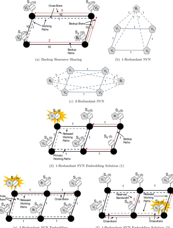
10 10 10 10 (10) (10) (10) (10) S 3 S 1 S 2 S 4 V1 V2 B1 1 2 Cross-Share Backup-Share 0 V3 2 Working Paths Backup Paths 2
(a) Backup Resource Sharing
1 1 1 1 V1 V3 1 V4 1 1 1 V2 B1 (b) 1-Redundant SVN V1 V3 1 V4 1 1 1 V2 1 1 11 B1 B2 1 1 1 1 (c) 2-Redundant SVN 1 1 1 1 1 1 1 (5) (5) (5) (5) (5) (5) V2 B1 Released Working Paths Primary Working Paths Backup Paths S 1 S 2 S 3 S 4 S 5 S 6 V1 V4 V3
(d) 1-Redundant SVN Embedding Solution (1)
(5) (5) (5) (5) (5) (5) V1 B1 V2 B2 1 1 1 1 1 1 1 Released Working Paths Cross-Share Cross-Share S 1 S 2 S 3 S 4 V3 V4 S 5 S 6
(e) 2-Redundant SVN Embedding
(5) (5) (5) (5) (5) (5) V2 B1 1 1 1 1 2 1 V3 1 Released Working Paths Cross-share Cross-share 2 Reserved Bandwidth S 1 S 2 S 3 S 4 S 5 S 6 V1 V4
(f) 1-Redundant SVN Embedding Solution (2)
Figure 3.2: Designing and Embedding Reliable VNs
withv1 with 2 units of bandwidth. Given that at any point in time eitherv2 orv3
would fail, it is sufficient to reserve 2 units of bandwidth on the link connectingb1
tov1. The set of backup links that are activated simultaneously upon the failure of
a virtual nodev are denoted as the Backup-Group ofv (BG(v)) [18]. For instance, the BG(v1) contains backup links (b1,v2) and (b1,v3). Similarly, the backup group
of BG(v2) andBG(v2) is (b1,v1).
Now, for the k-redundant scheme, the VN is augmented with k backup nodes, wherekrepresents the number of primary critical nodes. In this case, each backup virtual node protects a single primary node, and hence it only connects to its neighbors via backup virtual links. Each backup node along with its associated backup links will be provisioned with the same amount of resources as the primary node it protects and its adjacent links, respectively.
When a facility node fails, only the affected node will be disconnected from the substrate network. However, its adjacent network node and substrate links will remain active and capable of routing traffic. Thus, upon the failure of a facility node that hosts a virtual node v, the bandwidth on the original working paths that connect v to its neighbors in the substrate network will be released, and hence becomes available. This released bandwidth can thus be reused by the corresponding backup paths of v’s backup node. Such type of sharing is known as cross−sharing [18] between working and backup paths. Each virtual node v is associated with a working-group (W G(v)) that contains the set of v’s working paths. For instance, the W G(v1) contains (v1,v2) and (v1,v3). Hence, the BG(v1)
can reuse the bandwidth of the W G(v1) upon v1’s failure through cross-sharing.
Moreover, given that a single node might fail at any point in time, the backup paths belonging to different backup groups can share their bandwidth in the substrate network. Such type of sharing is referred to as backup−sharing [18]. Figure
3.2(a) shows a mapping solution for the 1-redundant SVN presented in Figure
3.2(c) over the substrate network in Figure 3.2(b). We observe that for backup link (b1,v3), 4 units of bandwidth needs to be reserved, since the substrate links
that route this backup path do not overlap with any other appropriate backup or working paths. However, backup paths (b1,v1) and (b2,v2) overlap over substrate
link{s2,s4}; and given that these backup paths belong to distinct backup groups,
only 2 units of bandwidth need to be reserved on substrate link {s2,s4}, rather
than 3 due to backup-sharing. Moreover, backup path (b1,v1) further overlaps with
working path (v1,v2) on substrate link {s1,s2}; hence 0 units of bandwidth needs
The problem with the 1-redundant and k-redundant schemes is that by forcing the number of backup nodes to be either 1 of k, we may end-up with infeasible or costly mapping solutions. This is due to the fact that the substrate might not have enough bandwidth capacity to route the traffic between 1 backup node to the neighbors of all critical nodes, in the case of the 1-redundant scheme. Whereas, in the case of thek-redundant scheme, a substantial amount of CPU resources remain idle until a failure occurs, since k-redundant requires as many backup nodes as primary critical nodes, not to mention the large number of backup virtual links needed to associate each backup node with its appropriate primary critical node. This motivates the need for a cost-efficient redesign technique that is capable of exploring the space between 1 andk, and finding the balance between the amount of provisioned CPU and bandwidth to yield feasible and cost-efficient embedding solutions.
3.3.2
Illustrative Example
To further illustrate the inconvenience of the conventional redesign techniques, consider the case of a 4 nodes VN in Figure 3.2, where each virtual node is con-sidered to be critical. Using the 1-redundant scheme, we augment this VN with a single backup node, connected to the neighbors of all critical nodes via backup virtual links, as illustrated in Figure 3.2(b). Now, consider a substrate network with 6 facility nodes interconnected via substrate links, each with a bandwidth capacity of 1 unit, as shown in Figure 3.2(d). Given the 1-redundant SVN, there exist no feasible mapping solutions on the aforementioned substrate network. For instance, consider embedding the SVN using the mapping solution illustrated in Figure3.2(d). When the substrate nodes1 fails, the virtual nodev1 migrates tob1
which needs to communicate with virtual nodes v2 and v4. b1 is capable of
reach-ing virtual node v2 through path {s3 → s2}. However, the substrate network’s
capacity, with the current embedding solution inhibits b1 from reaching node v4,
bandwidth on the substrate link {s4-s5}. This renders the embedding solution
il-lustrated in Figure 3.2(d)infeasible. By examining all possible mapping solutions of the 1-redundant SVN on the given substrate network, we find that they are all infeasible. This is because the 1-redundant scheme connects a single backup node to the neighbors of all critical nodes. Hence b1’s bandwidth demand along with
the given substrate network capacity, inhibits b1 from protecting this VN against
any single node failures.
On the other hand, consider the case where the aforementioned VN is augmented with 2 backup nodesb1 andb2, as shown in Figure3.2(c). b1 assumes the failure of
critical nodesv1 and v2, andb2 replacesv3 andv4 in case any of them failed. Upon
embedding the resultant SVN, we notice that this reliable design does indeed yield a feasible solution and requires 0 units of reserved bandwidth due to cross-sharing, as illustrated in Figure 3.2(e). For example, consider the case where the facility node s1 fails; subsequently, v1 will migrate to b1, and that latter needs to resume
v1’s communication with v2 and v4. The failure of virtual node v1 leads to the
release of the active bandwidth on working paths {s1-s2} and {s1-s4} connecting
virtual node v1 to v2 and v4, respectively. The released bandwidth will be reused
by b1 to reach v2 and v4 through cross-sharing. By employing cross-sharing for
all other virtual node failures in the given VN, we can conclude that indeed the 2-redundant SVN requires 0 unit of reserved bandwidth.
Further, consider the same substrate network, where link{s2 →s5}has a capacity
of 2 units, as illustrated in Figure3.2(f). In this case, we can indeed find a feasible embedding solution for the 1-redundant SVN with a provisioned bandwidth cost of 2 units, whereas the 2-redundant scheme still requires 0 units of provisioned bandwidth.
These motivational examples prove our proclamation that by forcing the number of backup nodes to be either 1 or k, we might end up with infeasible or costly mapping solutions. Whereas when we augment the VN withi (1≤i≤k) backup nodes (i = 2 in the above example), we achieve a balance between the amount of backup bandwidth and CPU that needs to be reserved. In fact, this balance yields a feasible solution, when the 1-redundant and k-redundant fail to find one.
This motivates the need for a redesign approach that is capable of finding that balance, rather than being fixed to either 1 or k backup nodes. By exploring the space in the range between 1 and k, we can obtain lower-cost mapping solutions, and increase the network’s admissibility. This is one of Pro-Red’s unique capa-bilities. Another advantage of Pro-Red is that it redesigns the VN in a way to promote the backup bandwidth sharing at the substrate network. In the next section we present Pro-Red’s theoretical foundation that enables it to fulfil these two promises.
3.4
Prognostic Redesign Approach (Pro-Red) :
3.4.1
Theoretical Foundation
V
11
V
2V
1V
2V
11
1
V
21
1
1
B
1B
2(a)
(b)
(c)
Figure 3.3: Theoretical Foundation
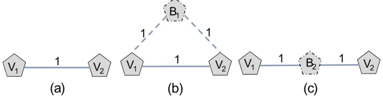
In this section, we present the theoretical foundation on which Pro-Red’s redesign technique is established. We begin our explanation with a motivational example: Consider a 2 nodes VN illustrated in Figure 3.3(a). Augmenting the VN with a single backup node, using the 1-redundant scheme, requires 2 units of reserved bandwidth (as shown in Figure 3.3(b)). By employing an effective embedding approach, this estimated bandwidth cost could be minimized at the substrate network level via cross-sharing and backup-sharing. Observe, however, that by placing this backup node along the path connectingv1 and v2, the resulting SVN
will require 0 additional units of bandwidth once embedded into the substrate network. This is due to the fact that by placing the backup node in between its associated primary nodes, we force the primary path that routes the traffic
between v1 and v2 in the substrate network to pass through b1 1. Subsequently, if
either one of these primary nodes fail, the backup node will cross-share (reuse) the released primary bandwidth. It should be noted here that this redesign approach is indeed prognostic to backup resource sharing, as it is able to predict (promote) the cross-sharing (bandwidth reuse) at the VN level. Indeed, throughout our numerical results, we show that Pro-Red achieves considerable gains in terms of reducing the total bandwidth cost against the conventional redesign techniques, and greatly decreasing the network’s blocking ratio.
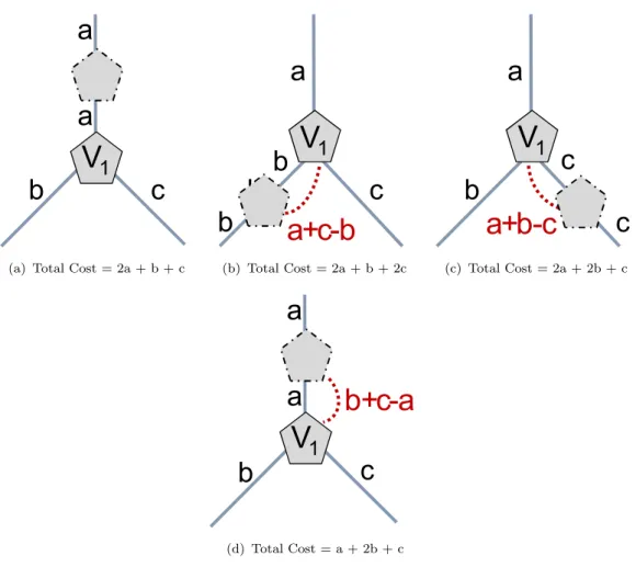
We build on this motivational example to formulate a novel redesign technique that determines the location of backup nodes in the VN, such that cross-sharing and backup-sharing can be fully exploited in the substrate network. Placing the backup node between every two virtual nodes is definitely costly in terms of idle CPU resources. Hence, we resort to clustering a subset of virtual nodes into distinct sets, where nodes in a particular set are covered by a single backup node. In each set, the backup node is positioned such that the maximum amount of backup resource sharing is guaranteed upon the embedding. This clustering technique can thus create a balance between the amount of provisioned backup nodes and links. To create a set, we begin by selecting the virtual node with the highest degree. This allows a larger number of primary virtual nodes to be clustered within a single set, which can substantially decrease the amount of reserved CPU resources. Once the starting node is identified, we place the backup node on the adjacent link with the highest bandwidth demand, which guarantees the most backup resource sharing. To support this analysis, consider the following example illustrated in Figure3.4. Letv1 be the node with the highest nodal degree 3. Its adjacent links
have a bandwidth demand of a, b and crespectively. We assume (without loss of generality) :
a > b+c > b > c (3.1)
In order to protectV1, we need to place a backup node on one of its adjacent links.
In this case, we have 3 different scenarios, we can either place the backup node on
1Note that once a backup node is placed between v1 and v2, the associated working path
V
1a
a
b
c
(a) Total Cost = 2a + b + c
V
1a
b
c
b
b
a+c-b
(b) Total Cost = 2a + b + 2cV
1a
b
c
c
a+b-c
(c) Total Cost = 2a + 2b + cV
1a
a
b
c
b+c-a
(d) Total Cost = a + 2b + cFigure 3.4: Designing Reliable VNs
the link with bandwidth demanda,b, orc. These different scenarios are illustrated in Figure3.4(a),3.4(b), and3.4(c), respectively. Notice that in the case where the backup node is placed on the link with the highest bandwidth demand a (shown in Figure3.4(a)), 0 units of reserved bandwidth is needed. In fact, by placing the backup node on this former link we can always achieve the lowest total cost, since upon failure the backup node is able to reach all ofv1’s neighbors by fully reusing
the released bandwidth through cross-sharing. Whereas, by placing the backup node on the link with bandwidth demand b (shown in Figure 3.4(b)) additional bandwidth needs to be reserved in order to reach v1’s neighbors. In fact, since b
< a, the backup node can never reachv1’s neighbor at linka without reserving an
additional (a - b) units of bandwidth. The same applies to reach v1’s neighbor at
link c, hence an overall (a + c- b) units of bandwidth needs to be reserved. This renders a total cost of (2a +b + 2c), which is obviously more expensive that the redesign solution presented in Figure 3.4(a). Note that in the case where a ≤ (b
+ c), and a is the link with the highest bandwidth demand; to place the backup node on link a, a total of (b + c - a) must be reserved, as illustrated in Figure
3.4(d). However, this solution still renders the lowest total bandwidth cost.
3.4.2
Pro-Red Algorithm :
Algorithm 1 Pro-Red: Prognostic Redesign Heuristic
1: Given V(U, E) /*Virtual Network Topology*/
2: /*Set cover flag for nodes and links to false*/
3: for (u ∈ U) do
4: u.covered = false;
5: end for
6: C ={ }; /*Initialize the list of covered nodes*/
7: while (—C— ¡ U) do
8: Cˆ ={U} - C;
9: Step 1: Find Starting Node
10: v1 =GetN odeW ithHighestN odeDegree( ˆC);
11: L = GetAllAdjacentLinks(v1, ˆC);
12: Step 2: Find Starting Link
13: e = GetHighestBW(L);
14: v2 =GetT heOtherN ode(v1, e);
15: Step 3: Create a new Set
16: s = CreateSet(v1,v2, e);
17: C =C ∪ {s};
18: end while
In this section, we present the SVN redesign heuristic that is founded on the the-ories and observations presented in Section 3.4.1. The objective of this algorithm is to assign a backup node for each critical node in the given VN topology; we refer to a critical node that is assigned to a backup node ascovered(or protected). Initially, all the virtual nodes in the VN topology are considered as uncovered; hence, we initialize the virtual nodes with a cover flag set to false. Next, we define two new sets C and ˆC that are updated at the