ITU-T RACF implementation for
application-driven QoS control in MPLS networks
B. Martini, F. Baroncelli
National Laboratory of Photonic Networks Consorzio Nazionale Interuniversitario per le
Telecomunicazioni (CNIT) Pisa, Italy
{barbara.martini, fabio.baroncelli}@cnit.it
V. Martini, K. Torkman, P. Castoldi
Center of Excellence for
Information and Communication Networks Engineering Scuola Superiore Sant'Anna
Pisa, Italy
{v.martini, karim.torkmen, castoldi}@sssup.it Abstract—Within the ITU-T Next Generation Network (NGN)
architecture, the Resource Admission Control Function (RACF) has been designated to perform the application-driven QoS control across both access and core networks. However, an actual RACF implementation acting on MPLS metro-core networks does not exist since RACF lacks of the capability to configure QoS policies on MPLS network nodes. This prevents an effective end-to-end QoS control in a metro-core scenario on a per-application basis.
This work presents a specific implementation of RACF operating over an MPLS network domain. This RACF implementation is applied to a testbed where a Video Client application requests a real-time video data transfer from a Video Server through an MPLS network. The admission control is performed upon service request based on video requirements and network resource availability. The differentiated traffic treatment on per-flow basis is realized through setting of MPLS DiffServ-aware Traffic Engineering (TE) capabilities using the NETCONF protocol. Effective traffic differentiation is achieved in a multi-service network scenario and thus it validates NETCONF as candidate protocol for policy provisioning in MPLS networks.
Index Terms—MPLS, TE, DiffServ, NGN, RACF I. INTRODUCTION
merging multimedia applications, such as Video on Demand (VoD), require real-time data transfer between customer’s terminals and content servers. Such transfer would benefit from having Quality of Service (QoS) guarantees enabled throughout the network for the whole duration of the content delivery. Whenever multimedia applications are supported in metro or wide area networks, the need for QoS control on a per-application basis across metro-core IP/MPLS networks arise.
Next Generation Network (NGN) [1] has been conceived by ITU-T as a packet-based network architecture capable of carrying telecommunication services with QoS guarantees independently from the underlying transport technology. By decoupling transport and service functionalities, the ITU-T NGN enables an innovative service provisioning relying on an intermediate functionality, named as Resource Admission
admission control of network service requests based on network resource availability. If the service is successfully admitted, RACF allocates the resources across the network to support such a service with the required QoS.
However, QoS control within NGN is a challenging issue mainly due to different and varying types of QoS mechanisms across the networks technologies [3][4]. ITU-T is devoting continuous efforts to extend the scope of RACF to include the control of resources in MPLS metro-core networks but some architectural aspects are still under discussion [5]. In addition, the specification of protocols used by RACF is currently under definition within ITU-T [6] but some protocols are either yet undetermined or they are still in draft status [7]. The lack of complete protocol specifications prevents a large-scale deployment of RACF, especially in case of MPLS networks. In fact, [6] foresees the use of DIAMETER [8] and COPS [9] protocols to enforce the QoS across the network. However, most network devices used in IP/MPLS metro-core networks neither support these protocols nor likely will support them in the future [10]. While diverse research activities on QoS mechanisms exist in optical networks [11][12], operative implementations of RACF for MPLS networks are scarce. Initial RACF implementation is presented in [7] but is mainly focused on inter-RACF communications.
This paper presents the implementation and the experimental validation of the ITU-T RACF for application-driven QoS control across an MPLS network. Upon a service request, the required network resources are reserved across the MPLS network domain to ensure that each application data flow can experience the proper QoS treatment. The differentiation of traffic treatment is obtained by exploiting DiffServ-aware Traffic Engineering (DS-TE) capabilities available in MPLS and performed through consistent configuration of edge nodes using NETCONF protocol [13]. DS-TE enables the resource reservation based on traffic classes while optimizing the use of network resources. NETCONF is a network management protocol standardized by IETF that enables a simple script-based interaction with network nodes thanks to the use of XML for data encoding
E
devices.
This research work is the result of authors’ background on dynamic and consistent configuration of MPLS network nodes as proved by [14] that proposes a signaling framework for automatic connectivity set-up. Moreover this work follows up the ITU-T RACF validation described in [15] that proposes enhancement to RACF to support GMPLS capabilities within NGN. Specifically, the RACF implementation presented in [15] has been enhanced with the capability to enforce application-specific traffic treatment on network nodes to provide the required QoS.
The paper is organized as follows. section II outlines an overview on NGN architecture and MPLS QoS techniques. Section III presents how the QoS control is performed by RACF during the VoD service provisioning. Section IV describes the RACF implementation in a real testbed and discusses the experimental results.
II. REVIEW OF ITU- NGN AND QOS MECHANISMS IN MPLS
This section presents an overview of QoS control architecture enabled by NGN and of DS-TE capabilities supported by MPLS. Extensive descriptions of the NGN architecture, QoS capabilities in MPLS and DiffServ technique can be found in [1][16][17].
A. QoS Control in ITU-T NGN
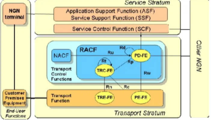
The key feature of NGN architecture (Fig. 1) is the functional independence of the service and transport functionalities [1], referred to as Service Stratum and Transport Stratum respectively.
The Service Stratum is responsible for the transfer of service control data, for the negotiation of service resources and for the establishment of network services to enable user services and applications. The Service Stratum consists of the Application Support Function (ASF) and the Service Support Function (SSF). The ASF and SSF “include functions such as the gateway, registration, authentication and authorization functions at the application level” [1]. They rely on Session Control Function (SCF) to support end-user and third-party applications with the requested NGN services. The SCFs “include resource control, registration, and authentication and authorization functions at the service level” and trigger the network resources reservation by interacting with the Transport Stratum [1].
Transport Stratum is responsible for the reliable transfer of data packets across both access and core networks. Moreover, it controls the network resources to address QoS requirements of traffic flows. The transport resource control is carried out by the Resource Admission Control Function (RACF)[2]. To the purpose of this work, RACF mainly consists of two specialized functional entities, namely the Policy Decision Functional Entity (PD-FE) and the Transport Resource Control Functional Entity (TRC-FE).
PD-FE determines the acceptance of the service request.
The decision is taken based on the pre-loaded network operation policy rules, the subscription profile (e.g., maximum bandwidth available in the access network to the end-user) provided by Network Attachment Control Function (NACF), the service requirements provided by SCF, and the resource-based admission outcome provided by the TRC-FEs. In fact, the TRC-FE retrieves the information about the network topology and resource state through the Transport Resource Enforcement Functional Entity (TRE-FE) in order to make resource-based admission decisions on behalf of a PD-FE. Once the decision is taken, PD-FE instructs the Policy Enforcement Functional Entity (PE-FE) to perform the actions on the traffic flows as required by the service request. These actions concern traffic policing (e.g., traffic shaping), packet filtering, QoS marking as well as actions needed for guaranteeing QoS across different domains such as Network Address Translation (NAT) control.
Figure 1. ITU-T NGN functional architecture
Reference points have been defined within RACF among the functional entities to support protocol specifications and development. Although completed for most of the reference points [3], protocol selection is still in progress within ITU-T [6].
B. DiffServ-aware MPLS Traffic Engineering
QoS control in MPLS network may resort to DiffServ capabilities [16] to differentiate packet treatment at each network node based on the Class of Service (CoS) which the packet belongs to. The CoS is identified by bits in the EXP field in packet header. Based on EXP value, the MPLS packets experience different Per-Hop Behavior (PHB) specified in terms of queue where the packet should be buffered for forwarding, resources (i.e., buffer and bandwidth) allocated to each queue, service rate and packet drop probability of each queue. However, DiffServ does not influence the path of packets and assumes that enough resources are available along the link to serve the traffic according to the marking. Thus the over-provisioning of link’s bandwidth is the only viable way to address QoS requirement of critical traffic flows even though it gives no guarantees in case of failure or congestion.
TE by combining TE and DiffServ capabilities [18]. DS-TE enables reservation of bandwidth on a per-class basis. This allows to meet QoS requirements of different traffic classes while optimizing the use of network resources. To differentiate the bandwidth reservation based on the type of traffic, [18] introduces the concept of the Class Type (CT). CT identifies a set of traffic flows crossing a link that share the same portion of link bandwidth. Therefore, the link bandwidth is partitioned among the different CTs and then advertised and reserved to set-up LSP on per CT-basis, called DS-TE LSP. By reserving the required portion of link bandwidth for each DS-TE LSPs and by setting queue scheduling policies accordingly, TE capabilities can adjust network resources among LSPs in a way that packet flows switched along such LSPs can experience the required PHB.
To exploit DS-TE capabilities, the following settings need to be performed during service provisioning to enforce the required treatment of packets as they enter the MPLS network. Specifically, the proper DS-TE LSP must be selected for each packet flow based on both application traffic class and destinations that are reachable at the egress node of the LSP. Then an admission control is advisable to prevent that a DS-TE LSP is fed with more traffic than its capacity. Finally, a consistent setting of EXP bit to each packet is required to enforce the PHB associated to that LSP. Admission control and traffic marking and forwarding are the main tasks performed by ITU-T RACF during the service provisioning.
III. VOD SERVICE PROVISIONING IN NGN
This section focuses on the operative aspects of the QoS control and on the NGN functionalities implemented and employed in the delivery of a real time service, i.e., Video On Demand (VoD).
To offer VoD, Service Providers employ integrated software platforms, commonly known as Service Delivery Platform (SDP) [19]. A typical SDP infrastructure includes the following entities:
• Video Head-end: it consists of the master facility for
production and/or collection of video contents that are stored, encrypted and finally replicated across the Content Distribution Network. The Video Head-end facility is directly connected to the metro-core networks.
• Content Distribution Network: it is constituted by the pool
of Video Servers that handle the customer service request and arrange the data transfer. Each Video Server controls a cluster of Video Content Devices that actually store the data content to be provided to customers. Video Servers and Video Content Devices may be located in either Video Head-End or Point of Presences (POP)s. In both cases, they are connected to the edge of the metro-core network.
• Service Management System: it is a collection of software
applications that coordinate and support the previous entities to monitor and control the overall content assets, the network transmission aspects as well as the collection of
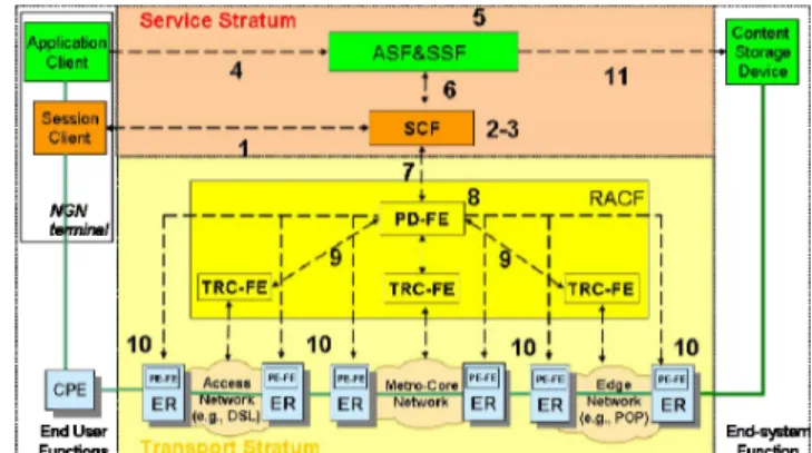
subscription and billing information. These software modules run in end-systems located in the central office of the Service Provider that in turn is connected to metro-core network via a broadband access network, e.g., dedicated SDH circuit (e.g., STMx) or optical channel (e.g., lambda). Fig. 2 shows the NGN functionalities as regards the considered VoD service delivery. The solid line represents the physical connectivity among systems, while the dashed line represents the signalling paths among NGN functionalities.
The End-User Function comprises the NGN terminal, e.g., Set Top Box (STB) or PC, that is connected to the NGN access network through the corresponding Customer Premise Equipment (CPE), e.g., xDSL modem or Integrated Access Device (IAD). The End-System Function comprises the Video Storage Data Base located in the POP that is selected for content provision to the end-user.
Figure 2. QoS control according to ITU-T NGN directives in VoD scenario The Service Stratum corresponds to the SDP infrastructure operated by Service Providers. The SCF in the Service Stratum refers to the application components within the SDP that deals with the control of content transfer. Specifically SCF performs:
•the selection of Video Server that is suitable for the provisioning of requested content,
•the activation of session related to the content transmission from the designated Video Server to the end-user,
•the control of content transmission process across the network.
These tasks are performed by SCF at the Video Servers with the support of the centralized Service Management Systems, e.g., to route the content requests to the appropriate Video Server and to monitor the performance of content transmission.
ASF&SSF in the Service Stratum refers to the application components within the SDP that deals with the control of service delivery aspects. Specifically, ASF&SSF performs:
• the selection of Video Storage Device,
• the collection and distribution of contents and their encryption for secure delivery to end-user,
• the management of subscriber information and relevant billing information.
Head-end equipments and at the designated Video Server with the support of the centralized Service Management Systems, e.g., to track information about content usage of each subscriber, and to plan the content distribution across the network.
Consequently, within the NGN terminal two different functions have been identified for the interaction with the Service Stratum. The Application Client interacts with the ASF&SSF for the content selection and for service profile customization. The Session Client acts as link between Application Client and the ASF&SSF through the SCF.
The transport stratum comprises the network infrastructure operated by Network Provider, including the equipments implementing the PD-FE, PE-FE, and TRC-FE. Specifically, the network infrastructure comprises the Access Network serving the end-user (e.g., DSL network), the Edge Network consisting in Point of Presence (POP), and finally the metro-core. Typically, the PE-FE resides in an equipment operating at the edge of the network such as Session Border Controller, Broadband Remote Access Server, Edge Router [3]. Alternatively, multiple functional entities can be implemented in the same physical device. For example, one equipment is likely to support PD-FE combined with TRC-FE [7].
A. Use Case
A use case is presented in this section to highlight the interworking among the NGN functionalities in case of VoD provisioning. Specifically, the use case shows how the processing of user service request activates the RACF intervention that finally results in a consistent network node configuration for QoS-assured content transfer. We suppose that a single PD-FE is responsible for both access and core network domain since it is supposed to belong to the same Network Provider. The QoS control using push mode [3] is considered. The following operative steps illustrated in Fig. 2 are identified:
1.The Session Client issues a VoD service request to the SCF. The service request contains the customer identifier, service type (i.e., VoD).
2.The SCF (i.e., Video Server receiving the request) processes the service request and, based on the customer identifier, obtains the subscriber profile and the customer network location. SCF identifies the proper ASF&SSF (e.g., appropriate Video Server) to provide video content to that customer.
3.SCF activates a service session to control the transmission of the content. Then SCF returns the IP address of designated Video Server to the NGN terminal (not shown in Fig. 2).
4.The Application Client contacts the ASF&SSF (e.g., by generating an HTTP request to the Web portal of Service Provider) to issue a Video Provisioning Request to the ASF&SSF. The request contains the selected content identifier and the service parameters, such as the encoding format, the delay bound, the maximum bandwidth.
5.The ASF&SSF elaborates the Video Provisioning Request and finds an available Video Storage Device suitable for satisfying the delivery of requested video to the requesting NGN terminal.
6.When a Video Storage Device is found, the ASF&SSF issues an end-to-end Network Service Request to the SCF to arrange for proper data transfer across the network. Such a request contains the IP addresses of both NGN terminal and Video Storage Device and the required service parameters specified at step 4.
7.The SCF elaborates the Network Service Request. From service parameters within the request, SCF extracts the requirements for network resource reservation in terms of required service (i.e. video) and quality of data transmission (i.e., gold, silver, bronze). Then SCF issues a Resource Request to the PD-FE of the core network. Such a request contains the IP addresses of both NGN terminal and Video Storage Device and the abovementioned QoS requirements.
8.PD-FE processes the Resource Request and performs a preliminary admission control based on Network Provider policy. We suppose that subscription check to NACF is not necessary since such information is considered pushed to PD-FE upon the attachment of CPE to the network.
9.The PD-FE checks for the bandwidth availability in both the core and access network segment provided by respective TRC-FE.
10.After the results of the policy check, subscription check and resource availability check, the PD-FE performs the policy enforcement on the PE-FE at the border of each network.
11.Upon receiving the acknowledgment of the resource reservation from SCF (not shown in Fig. 2), the ASF&SSF issues a Video Transmission Command to the Video Storage Device specifying the IP address of the NGN terminal and the video content to provide.
IV. EXPERIMENTAL SET-UP
This section presents the testbed used to validate the implementation of RACF designed for MPLS networks and examines the policy enforced on MPLS edge routers to achieve the QoS requested by VoD.
A. Testbed description
The testbed, shown in Fig. 3, implements an NGN infrastructure and reproduces the use case described in section 3 for the delivery of a High Definition (HD) VoD service.
The Service Stratum is represented by a commercial PC running a software application that implements the core functions of a Video Server, i.e., the processing of service requests from a Video Client, the selection of a Video Storage Device and the issuing of a resource reservation request to RACF prototype. The End-User function is represented by a second commercial PC running a software application that implements the core function of a Video Client, i.e. the issuing of service requests to Video Server, and an instance of the
MithVideo media player v0.21 [20] configured for receiving the HD video streams. The End-System function is represented by three Content Storage Devices implemented using Linux Boxes running a commercial software for the generation of HD video streams. This reflects the real scenario of a POP hosting multiple devices that may store diverse and backed-up multimedia contents (e.g., audio, video and streaming).
Figure 3. The Testbed
The Transport Stratum consists of an instance of RACF, a MPLS metro-core network and an Access Network. The RACF implementation comprises a Linux Box running an instance of PD-FE, and two Linux Boxes each running an instance of TRC-FE. All the Linux Boxes are equipped with Linux v2.6 operating system and have public IP addresses to assure the complete reachability of such RACF functionalities. Each Linux-Box running TRC-FE instances is connected to the MPLS edge routers via a dedicated Ethernet interface for issuing NETCONF directives. The implementation of both the PD-FE and the TRC-FE has been described in [15]. In comparison to [15], PD-FE and TRC-FE implementations have been enhanced with the capability to enforce application-specific traffic treatment on network nodes deduced by the service request.
The metro-core network comprises six IP/MPLS routers that are interconnected as shown in Fig. 3. The routers called ER1, ER2 and ER3 are configured as provider Edge Router (ER). The routers named CR are configured as core routers. All the six routers are equipped with Fast Ethernet (FE) interfaces and support MPLS, OSPF, and RSVP protocols with extension for DS-TE.
The Access network connects the Customer Premise Equipment (CPE) to ER2 using a VLAN logical connection, namely “VLAN customer1”. The Content Storage Devices are connected to ER1 through a L2 switch. Such a switch is
configured to support three VLAN connections, one for each device towards ER2, to segregate the service flows entering the MPLS network. We named “VLAN-video”, the VLAN that is used in the experimental validation of RACF prototype. To deploy DS-TE solution, four traffic categories (i.e., CTs) corresponding to the four PHBs supported by MPLS routers have been identified [21] [22]:
• Network control (NC): reserved for control messages that require delivery assurance but it may tolerate delay.
• Expedited forwarding (EF): reserved for voice traffic as it requires minimal delay and loss.
• Assured Forwarding (AF): reserved for video traffic since it requires rate assurance but can tolerate limited delay or jitter.
• Best effort (BE): reserved for data traffic that does not require any QoS assurance.
Accordingly, the following DS-TE LSPs are established between ER1 and ER2 with the specified reserved bandwidth:
• LSP-NC (1 Mbit/s) used to deliver control messages .
• LSP-voice (3 Mbit/sec) used to deliver voice traffic.
• LSP-video (80 Mbit/s) used to deliver the HD video.
• LSP-BE used to carry the best-effort traffic.
The link bandwidth reserved to each LSP depends on available bandwidth of the physical link (i.e., 100 Mbit/s) and bandwidth requirements of each CT. Most of the available link bandwidth (i.e., 80 Mb/s) has been allocated for video traffic. Since a single flow requires 20 Mbit/s [23], this setting allows the support of up to four simultaneous HD video transmissions. The bandwidth for LSP-BE has not been specified as this CT takes the remaining available bandwidth of the link.
After the LSP establishment, the DiffServ settings are loaded in both core and edge routers, i.e., the setting of priority and transmit rate of each output queue. The priority determines the order in which the queues are served by the scheduler to forward the packets on the output link. According to the priority level of Weighted Round Robin scheduling technique [21], we assigned the “strict-high” priority to the NC queue, the “high” priority to the AF and EF queues and finally the “low” priority to BE queue. The transmit rate specifies the service rate of each queue and hence the rate of packet transmissions in the corresponding LSP. The transmit rate of AF queue at the output interface of ER1 is set to 40MB/s to serve up to two HD video transfers. If more request arrives such value needs to be updated to support the required traffic along the LSP-video.
B. Admission control and traffic policy enforcement upon service request
This section describes the settings on edge routers to be performed upon the service request to enforce the required QoS treatment at video packet flow entering the MPLS network. Such settings must guarantee the proper packet forwarding to the LSP associated to the required PHB and the consistent EXP bit marking as packets enter such LSP during the service delivery. The selection of LSP depends on the required service and on the respective location of both CPE and Video Storage Device that determines the edge routers involved in the data transfer. In this case the LSP-video connecting ER1 and ER2 is selected. The EXP setting on packets entering the MPLS network depends on the traffic category, i.e. CT, the application packets belong to. In this
case the packet flow generated by the Video Storage Device needs to be marked as AF. The criteria we implemented to identify such packet flow is on VLAN-basis.
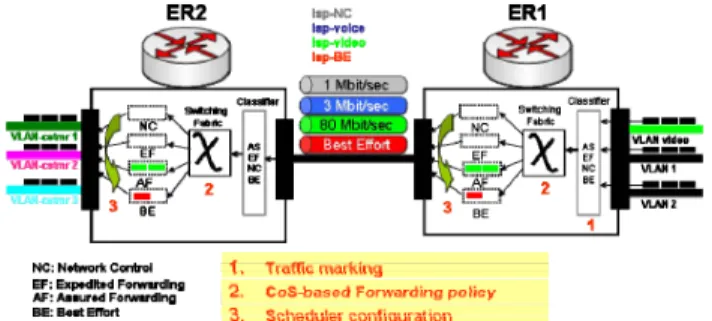
Figure 4. Internal routers process and mechanisms
Fig. 4 shows the functional blocks that need to be consistently configured in ER1 and ER2. Such configurations are required to create the association “incoming VLAN video-AF CoS-outgoing LSP video” in ER1 and the association “incoming LSP video-AF CoS-outgoing VLAN customer1” in ER2. This binding needs to be configured upon service request because VLAN identifiers are not known in advance. They depend on the VLAN established on the edge MPLS routers at the moment service request, as well as on the customer network location and selected Content Storage Device that affect the edge routers involved in service delivery. Specifically the settings relevant to ER1 router are:
• Traffic marking: packets coming from incoming
“VLAN-video” are marked with the proper CoS (i.e., AF)
• CoS-based Forwarding policy: based on CoS the outgoing
LSP-video is specifies
• Queue configuration: if needed, transmit rate of the output
queue is configured
The transmit rate of the AF queue in the output interface of ER1 is incremented of 20MB/s only in case it is not able to sustain an additional data transfer.
The setting relevant to ER2 router are:
• CoS-based Forwarding policy: based on CoS, the output
VLAN-customer1 is specified
• Queue configuration: transmit rate of the output queue are
configured.
The traffic marking within ER2 is done during the initial DiffServ configuration. In fact, it can be fixed a priori since the marking regards packets coming from per-service LSP. The transmit rate of the AF queue in the output interface of ER2 is set upon service request to reserve the bandwidth in the access link only for the duration of the video delivery service.
C. Testbed Message flow
In this section the message flow that implements the dynamic QoS enforcement is presented. The operative steps are in accordance with the use case described in section 3.B. These steps are regulated by the Finite State Machines (FSM) implementing the PD-FE and TRC-FE. The state transitions are driven by the exchange of XML messages.
Referring to Fig. 5, the Video Client sends a “Video Service Request” (1) to Video Server. Such a request contains the customer identifier, the list of codec, the supported bit rate, and the maximum tolerated delay. The Video Storage Device suitable for the content delivery to that customer is supposed to be pre-registered to Video Server as well as information related to network connection of Video Client. Thus Video Server application is able to directly obtain IP addresses of both Video Storage Device and Video Client starting from the customer identifier.
The Video Server sends a “Service Request” (2) to the PD-FE to reserve resources for a QoS-enabled data transfer across the MPLS network. Such a request contains the IP addresses of the Video Client and Video Storage Device as well as the service parameters extracted from (1), i.e. the type of requested service (i.e., video) and the quality level (i.e., “gold” since the HD video is considered). Starting from the addresses of the Video Client and Video Storage Device, the PD-FE obtains the addresses of the relevant ERs (i.e., ER1, ER2), and
of the TRC-FEs connected to those ERs (i.e., TRC-FE1,
TRC-FE2). In addition, the VLAN identifiers connecting ER1 and
ER2 respectively to Video Storage Device and Video Client is obtained, i.e., VLAN-video and VLAN-customer1. This information is periodically collected at regular intervals by each TRC-FE at the network boundary as explained in [15]. Then, the PD-FE translates the service parameters into network resource requirements, i.e. needed bandwidth (i.e., 20Mbit/s for HD video transfer) and category of traffic (i.e., rate-assured traffic). Subsequently, the PD-FE sends a “Resource Availability Request“(3) to TRC-FE1 linked to ER1
containing such requirements.
Upon receiving “Resource Availability Request”, the TRC-FE1 sends a “LSP-video Bandwidth Request“ (4) to the ER1 to
get the bandwidth that is actually used by existing video packet transfers. Specifically, the transmit rate of AF queue at the output interface towards ER2 is requested. When receiving the “LSP-video Bandwidth Response” (5), the TRC-FE1
compares the available bandwidth with the requested bandwidth and sends the “Resource Availability Response” (6) to PD-FE. If the bandwidth is available, the PD-FE sends to the PE-FE of both ER1 and ER2 the “Policy Enforcement Request” (7) to enforce the proper traffic policy as described in the section 4.B.
Each PE-FE performs the requested configuration and sends the “Policy Enforcement Response” (8) to the PD-FE containing information about the success or failure of such configuration. Accordingly, the PD-FE sends the “Service Response” (9) to Video Server with the value ACK if the configuration has been properly performed, otherwise it sends a NACK. In case resource reservation has been successfully realized, the Video Server issues a “Start Video Transmission” (10) to the Video Storage Device specifying the IP address of Video Client and selected content. Then the Video Server sends a “Video Service Response“(11) to Video Client announcing the forthcoming content transmission.
Figure 5: Testbed message flow diagram D. Testbed performance
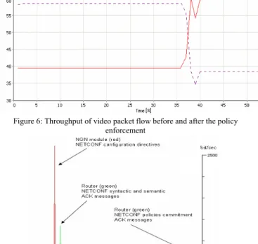
To demonstrate the effectiveness of DS-TE settings described in sections 4.B, we evaluated the throughput of a video packet flow before and after the policy enforcement performed by RACF prototype. Specifically, we transmitted across the MPLS network two traffic flows, both of them enter the MPLS network at ER1 and exit at ER2. The first traffic flow is composed of three HD video streams generated by the Content Storage Devices and direct to the Video Client. Two of these video streams enter ER1 through VLANs mapped in advance to LSP-video. Thanks to this mapping and to the initial settings of AF transmit rate at the output of ER1 (i.e., 40 MBit/s), these two video streams can benefit of the proper treatment across MPLS network. The third video stream enters at ER1 through a VLAN-video not mapped to LSP-video and therefore it is treated as best effort traffic before the policy enforcement. To reproduce a real network scenario with a random traffic load, we injected extra “background” traffic flow in both ER1 and ER2. Such traffic at 60Mbit/s is generated by a router tester connected to ER1 and directed to an end host connected to ER2. Since the same output interfaces at ER1 and ER2 are involved, a traffic congestion is created in these interfaces and we can verify if the reserved network resources allows to maintain the assured bandwidth for video streams as a result of a joint traffic policy enforcement at ER1 and ER2. The solid line and the dashed line, depicted in Fig. 6, represent respectively the throughput of the aggregated video flows and of the “background” traffic flow measured at the ER2 output interface. The measured throughput regards the video stream packets without L2 or L3 encapsulation.
The total link bandwidth (100 MBit/s) is shared among these flows according to the reserved resources to the video traffic. The policy enforcement performed by RACF prototype is demonstrated by the sharp discontinuity of throughput achieved after the configurations. Before the policy enforcement, the throughput of the aggregated video packet
flow is 40Mbit/s because the initial settings assure resources for proper transmission of two video flows. The remain bandwidth (60 Mbit/s) is shared by the third video flow with best-effort treatment and the ”background” traffic flow. After the policy enforcement, the 60Mb/s are reserved and guaranteed also for the third video packet flows while the rest of available bandwidth is assigned to the best effort traffic.
[s] [s]
Figure 6: Throughput of video packet flow before and after the policy enforcement
Figure 7: Router commitment time
In Fig. 7 the timing of message elaboration at the routers is shown. The elapsed time required to process the configuration directives, apply the traffic policy, and respond to the controlling TRC-FE (see Fig. 5, arrows 7-8) is the router commitment time and is about 3.5 sec. Such time represents the total time required to apply policies in the MPLS network
since the QoS enforcement on routers occurs in parallel. This results combined with those presented in [24] suggest that NETCONF is a good candidate protocol for policy enforcement in MPLS networks.
V. CONCLUSION
In this paper an ITU-T RACF implementation has been presented. Specifically a real scenario of HD VoD has been reproduced to experimentally validate the QoS control on per-application basis in MPLS networks. The QoS control is achieved by exploiting the DS-TE capabilities and is performed through consistent configuration of edge nodes using NETCONF protocol The effectiveness of application-driven QoS enforcement based on DS-TE has been validated by throughput measurement of video traffic flow in a congested link. In addition, the commitment time of NETCONF configuration has been measured showing that NETCONF is a valid candidate protocol for policy enforcement in MPLS networks where COPS and DIAMETER are neither actually deployed nor will be likely supported.
Another contribution of this work is the contextualization of RACF operation in a real service delivery scenario. The presented use case highlighted the interworking of the NGN functionalities, the mapping of application service requirements into network-related requirement, and the mapping of end host address into edge node address serving that end host. Such address mapping is possible thanks to the ability of the presented RACF prototype to retrieve and process the topology information at the boundary of MPLS network. This demonstrates the feasibility of the decoupling of the service-related aspects from network-specific details with benefits for both Service and Network Providers. Finally, this work opens the way for an effective end-to-end QoS control by coordinating the proposed QoS enforcement mechanisms with existing QoS control procedures that can be dynamically established across access networks, e.g., DSL networks.
As future work, we plan to differentiate the MPLS-specific traffic policies enforced on TRE-FEs, i.e. DiffServ settings, and the service-related policies enforced on PE-FEs, i.e. forwarding rules and packet marking. This will allow to transparently adjust the traffic treatment across MPLS network during the service delivery to maintain the QoS performance perceived by the customer (e.g., in case of congestion of service requests).
ACKNOWLEDGMENT
The work described in this paper was carried out with the support of the BONE-project (“Building the Future Optical Network in Europe”), a Network of Excellence funded by the European Commission through the 7th ICT-Framework Programme, and MUR under FIRB project “Software and Communication Platforms for High Performance
REFERENCES
[1] ITU-T Y.2012, “Functional requirements and architecture of the NGN release 1,” September 2006
[2] ITU-T Y.2111, “Resource and admission control functions in next generation networks,” September 2006
[3] J. Song, M.Y. Chang, S.S. Lee, J. Joung, “Overview of ITU-T NGN QoS Control,” IEEE Commun. Mag., vol. 45, September 2007
[4] Hui-Lan Lu, “Resource and Admission Control for Next Generation Networks,” ITU-T Workshop “NGN and its Transport Networks”, Kobe, April 2006
[5] ITU-T Draft Rec.Y.RACF-MPLS, “RACF for MPLS Based Core Networks”
[6] ITU-T Rec. Q.3300 “Introduction to the Q.330x Series of Recommendations,” January 2008
[7] Y. Zhou, X. Xiao, C. Du, J.A. Zhou, “Field trial of end-to-end QoS cotnrol based on RACS,” Proc. ICCS 2006, UK, Reading, May 2006 [8] P. Calhoun, J. Laughney, E. Guttman, G. Zorn, J. Arkko, “Diameter
Base Protocol,” IETF RFC 3588, September 2003
[9] D. Durham, J. Boyle, R. Cohen, S. Herzog, R. Rajan, A. Sastry, “The Common Open Policy Service protocol,” IETF RFC 2748, January 2000 [10] E. Brendel, “Bridging the gap between Service and Network Control,”
Workshop on Programmable Routers for the Extensible Service of Tomorrow (PRESTO), New Jersey, Princeton, May 2007
[11] T.Shan, Oliver W.W. Yang, “Bandwidth Management for Supporting Differentiated-Service-Aware Traffic Engineering,” IEEE Transactions On Parallel and Distributed Systems, vol.18, no.9, September 2007 [12] J. Barakovic, H. Bajric, A. Husic, “QoS Design Issues and Traffic
Engineering in Next Generation IP/MPLS Network,” 9th International Conference on Telecommunications (ConTel) 2007, Croatia, Zagreb, June 2007
[13] R. Enns, ”NETCONF Configuration Protocol,” IETF RFC 4741, December 2006
[14] F. Baroncelli, B. Martini, V. Martini, and P. Castoldi “A distributed signaling for the provisioning of on-demand VPN services in transport networks,” Integrated Network Management (IM) 2007, Germany, Munich , May 2007
[15] F. Baroncelli, B. Martini, V. Martini, and P. Castoldi "Supporting Control Plane-enabled Transport Networks within ITU-T Next Generation Network (NGN) architecture,” Network Operation and Management Symposium (NOMS) 2008, Brazil, Salvador, April 2008 [16] F. Le Faucheur, L. Wu, B. Davie, S. Davari, P. Vaananen, R. Krishnan,
P. Cheval, J. Heinanen, “Multi- Protocol Label Switching Support of Differnetiated Services,” IETF RFC 3270, May 2002
[17] S. Blake, D. Black, M. Carlson, E. Davies, Z. Wang, W. Weiss, “An Architecture for Differentiated Services”, IETF RFC 2475, December 1998
[18] F. Le Faucheur, W. Lai, “Requirements for Support of Differentiated Service Aware MPLS Traffic Engineering,” IETF RFC 3564, July 2003 [19] C. J. Pavlovski “Service Delivery Platform in Practice,” IEEE Commun.
Mag., vol. 45, March 2007 [20] http://www.mithtv.org
[21] B. Davie, A. Charny, J.C.R. Bennet, K. Benson, J.Y. Le Boudec, W. Courtney, S. Davari, V. Firoiu, D. Stiliadis, “An Expedite Forwarding PHB,” IETF RFC 3246, March 2002
[22] J. Heinanen, F. Baker, W. Weiss, J. Wroclawsky, “Assured Forwarding PHB Group,” IETF RFC 2597, June 1999
[23] M. Alvarez, E. Salami, A. Ramirez, M. Valero, “A performance characterization of high definition digital video decoding using H.264/AVC,” Proc. of IISWC 2005, Texas, Austin, October 2005 [24] T.F. Franco, W.Q. Lima, G. Silvestrin, R.C. Pereira, M.J.B. Almeida,
L.M.R. Tarouco, L.Z. Granville, A. Beller, E. Jamhour, M. Fonseca, “Substituting COPS-PR: an evaluation of NETCONF and SOAP for policy provisioning,” Proc. POLICY’06, Canada, London, June 2006