http://researchcommons.waikato.ac.nz/
Research Commons at the University of Waikato
Copyright Statement:
The digital copy of this thesis is protected by the Copyright Act 1994 (New Zealand). The thesis may be consulted by you, provided you comply with the provisions of the Act and the following conditions of use:
Any use you make of these documents or images must be for research or private study purposes only, and you may not make them available to any other person.
Authors control the copyright of their thesis. You will recognise the author’s right to be identified as the author of the thesis, and due acknowledgement will be made to the author where appropriate.
You will obtain the author’s permission before publishing any material from the thesis.
Development of Recycled Polypropylene
Composite Materials for Applications in
3D Printing
A thesis
submitted in fulfilment of the requirements for the degree
of
Master of Engineering (Mechanical)
at
The University of Waikato
by
David Stoof
Abstract
The adverse effects that waste plastics are having on the environment is becoming increasingly apparent. However, the plastics recycling industry in New Zealand is entirely market driven, necessitating the development of new markets to account for increasing quantities of waste. Innovations in additive manufacturing (AM) have presented opportunities to recycle thermoplastics for use as AM feedstock material. Using waste thermoplastic materials to fabricate composites in this way, adds value to the polymer by enhancing mechanical and aesthetic properties.
The main objective of this research was to produce strong, stiff and dimensionally consistent composite AM feedstock material using recycled polypropylene. Alkali treated natural hemp and harakeke fibres were chosen as composite constituents based on the advantages gained in terms of mechanical performance as well as low environmental impact compared to synthetic fibres. In addition, recycled gypsum powder (which is a currently underutilised waste product), was selected as a composite constituent primarily to investigate the influence it has on polymer shrinkage.
Initial screening tests using 20 wt% harakeke fibre were conducted to determine effective AM feedstock filament fabrication parameters, which were then used to fabricate all subsequent composite filaments. The parameters that provided the most significant improvements in tensile properties were: 105oC constituent drying temperature for approximately 24 hours (as opposed to 80oC), Maleated polypropylene (MAPP) coupling agent in powdered form (as opposed to granulated form) and initial compounding carried out on a 16mm twin screw extruder (as opposed to a larger more intensive, 20mm extruder).
A range of composite filaments with differing fibre and gypsum weight contents were then produced using pre and post-consumer polypropylene (PP). The most successful filaments in terms of tensile properties consisted of 30 wt% harakeke in a post-consumer PP matrix which had a tensile strength and Young’s modulus of 41MPa and 3.8 GPa respectively. Comparing these results to those of plain PP filament, showed improvements in tensile strength and Young’s modulus of 77% and 275% respectively.
To investigate the effects of 3d printing on tensile properties, feedstock filaments were 3d printed into tensile test samples. Compared to the filaments, 3d printed samples showed a reduction in tensile strength and Young’s modulus as large as 40% and 60% respectively. An investigation was conducted to determine the cause of this reduction which was considered possibly due to moisture absorption and/or reduction of printing pressure relative to extrusion pressure. Pre-drying materials prior to printing resulted in strength and stiffness improvements, relative to undried filament of up to 26% and 44% respectively supporting moisture absorption to be an issue. However, densities were also found to be reduced, predominantly in the fibre reinforced materials supporting reduced pressure to also be a contributing factor. Specific strength and stiffness values of filament and printed materials were found to be closer than strength and stiffness, further supporting the relationship between a decrease in density and mechanical properties. Unlike fibre reinforced samples, the difference in specific strength and stiffness for plain PP filament and printed materials was equal to the difference in strength and stiffness. This could also suggest loss of polymer orientation to be a factor.
Finally, a novel method of measuring shrinkage in 3d printed components was developed and used to compare relative shrinkage of different composites. Natural fibre composites showed less shrinkage than gypsum composites with 10 wt% natural fibre showing a similar shrinkage value (1.17 %). as 50wt% gypsum. The composite that showed the least shrinkage consisted of 30 wt% harakeke with a shrinkage value of 0.34% corresponding to a net reduction of 84% relative to plain PP.
Acknowledgments
Of all the people that I have to thank for assisting me through my studies nobody has helped me more than my mother Sandy Wotton. Selflessly offering advice and assistance whenever possible she has played a pivotal role in my studies.
I would also like to thank my Father for all the conversations that have maintained excitement in my field of research and my studies.
The combination of enthusiasm, ceaseless curiosity and academic intuition make Professor Kim Pickering an exciting person to learn from and develop ideas with. This work could not have been carried out without her encouragement for which I am most grateful.
To Cheryl Ward I would like to say that I have really appreciated the selfless help you have offered throughout my studies. Your calm and collected attitude has preserved my sanity more than once.
I would like to thank my partner Felicia, who has sacrificed a lot to help me with my studies. I also appreciate her politely enduring conversations about the future of 3d printing.
I would also like to thank the Waikato district and Hamilton city councils for their financial support during this project. I hope that this research aligns well with their respective plans for the future.
I would also like to thank all of the technical staff, especially Chris Wang, Yuanji Zhang and Helen Turner who have always been there to offer wisdom and assistance.
Table of Contents
Abstract ... i
Acknowledgments ... iii
Table of Contents ... iv
List of Figures ... viii
List of Tables ... xii
Chapter: Introduction ... 1
1.1 Overview of Polymers and Polymer Recycling in New Zealand ... 1
1.2 Overview of Composite Materials ... 4
1.3 Natural Fibre Reinforced Composites ... 5
1.4 The 3d Printing Industry and The Opportunities For Enhanced Materials ... 8
1.5 Research Objectives ... 11
Chapter 2: Literature Review ... 12
2.1 Natural Fibres ... 12
2.2 Plant Based Natural Fibre Constituents ... 13
2.2.1 Cellulose ... 13 2.2.2 Hemicellulose ... 15 2.2.3 Lignin ... 15 2.2.4 Pectin ... 15 2.3 Hemp Fibre ... 16 2.4 Harakeke Fibre ... 16 2.5 Gypsum Powder ... 17 2.6 Thermoplastic Matrices ... 18 2.6.1 Polypropylene ... 19 2.6.2 Polymer Shrinkage ... 20 2.6.3 Polymer Rheology ... 21
2.7 Natural Fibre Composites and the Factors Influencing Effective
Fabrication ... 23
2.7.1 Fibre Orientation ... 23
2.7.2 Fibre Aspect Ratio ... 24
2.7.3 Moisture Absorption ... 25
2.7.4 Thermal Stability ... 25
2.7.5 Methods of Improving Interfacial Adhesion between fibre and matrix ... 26
2.7.6 Fibre Volume Fraction ... 28
2.8 Particle Reinforced Thermoplastic Composites ... 29
2.9 Processing of Short-Fibre Reinforced Composites ... 30
2.9.1 Extrusion ... 30
2.10 3d Printing Technologies and Their Potential Implications for Composite Fabrication. ... 32
2.10.1 Stereolithograghy ... 32
2.10.2 Micro Stereolithography (MSL). ... 33
2.10.3 Stereolithography and Microstereolithography Composites ... 35
2.10.4 Selective Laser Sintering (SLS). ... 36
2.10.5 Selective Laser Sintering Composites ... 36
2.10.6 Fused Deposition Modelling (FDM) ... 38
2.10.7 Fused Deposition Modelling Composites. ... 39
Chapter 3: Materials and Methods ... 43
3.1 Experimental Overview ... 43
3.2 Composite Material Constituents. ... 44
3.2.1 Pre-Consumer Recycled Polypropylene ... 44
3.2.2 Post-Consumer Recycled Polypropylene Woven Bags ... 44
3.2.3 Hemp Fibre ... 45
3.2.4 Harakeke Fibre ... 46
3.3 Composite Fabrication ... 49
3.3.1 Pre-Consumer PP Composite Compounding ... 49
3.3.2 Post-Consumer PP Composite Compounding ... 49
3.3.3 Filament Fabrication ... 50
3.4 3d Printing ... 53
3.4.1 Composite Tensile Testing ... 54
3.4.2 Shrinkage Testing of 3d Printed Parts ... 54
3.4.3 Density Measurements ... 55
Chapter 4: Results and Discussion ... 56
4.1 Tensile Strength and Stiffness of Initial Screening Composites ... 56
4.1.1 Microscopic Evaluation ... 58
4.2 Pre-consumer Polypropylene Composites ... 61
4.2.1 Tensile Strength and Stiffness of Hemp and Harakeke Fibre 3d Printing Filament ... 61
4.2.2 Influence of Fibre Content on Filament Fabrication ... 63
4.2.3 3D Printed Samples ... 64
4.2.4 Tensile Strength and Stiffness of Recycled Gypsum 3d Printing Filament ... 68
4.2.5 Microscopic Evaluation ... 70
4.2.6 Shrinkage ... 72
4.3 Post-Consumer Polypropylene Composite Results ... 74
4.3.1 Tensile Strength and Stiffness of Hemp and Harakeke Reinforced 3d Printing Filament ... 74
4.3.2 Microscopic Evaluation ... 76
4.3.3 3d Printed Samples ... 79
Chapter 5: Conclusions ... 86
5.1 Processing of 3d Printing Filament ... 86
5.2 3mm Composite Filament Results ... 87
References... 90 Appendix ... 100
List of Figures
Figure 1.1, Plastic numbering system ... 2
Figure 2.1, Types of natural fibres ... 12
Figure 2.2, Composition of natural fibres ... 13
Figure 2.3, Chemical structure of cellulose [26] ... 14
Figure 2.4, Microstructure of the cotton fibre showing the angle of fibrils with respect to the fibre axis [27] . ... 14
Figure 2.5, SEM image of needle shaped gypsum microstructure [41] ... 17
Figure 2.6, Molecular composition of polypropylene [52]. ... 19
Figure 2.7, Structure of monomer chains for semi-crystalline polymers [55] ... 20
Figure 2.8, Laminar flow of polymer through cylindrical die [59] ... 21
Figure 2.9, Development of sharkskin in LLDPE extrudates [49] ... 22
Figure 2.10, Representation of different modes of fibre orientation [70] ... 23
Figure 2.11, Low and high fibre volumes distributed in matrix material [73]... 25
Figure 2.12, Improvement in mechanical properties with 30 wt% fibre (left) and 50 wt% fibre (right) when combined with MAPP coupling agent ... 27
Figure 2.13, Effect of increased fibre loading on Young’s modulus and tensile strength of kenaf/PLA composites [88] ... 28
Figure 2.14, Correlation between talc content and shrinkage for talc/PET composites [90] ... 29
Figure 2.15, Twin extrusion screw set up including mixing and feeding regions [93]. ... 30
Figure 2.16, Cross section of extrusion [84] ... 31
Figure 2.17, Schematic view of a SL machine [96]. ... 32
Figure 2.18, Scanning microstereolithography [99]. ... 33
Figure 2.19, Projection microstereolithography.[99] ... 33
Figure 2.20, Micro lattices produced with microstereolithograpgy [100] ... 34
Figure 2.21, Carbon fibre turbine blade section produced through stereolithography [105] ... 35
Figure 2.22, SEM image of interface between carbon fibre and polymer matrix
[105] ... 35
Figure 2.23, Selective laser sintering process [97]. ... 36
Figure 2.24, Wax infused SLS produced wood Powder composite ... 37
Figure 2.25, SEM image of wax infused wood powder composite interface. ... 37
Figure 2.26, Fused deposition modelling system [97] ... 38
Figure 2.27, Fibre alignment of sample [95]... 39
Figure 2.28, Stress vs strain graph for longnitudal and transverse aligned fibres [95]. ... 40
Figure 2.29, SEM image of filament cross section [17]. ... 41
Figure 2.30, Continuos fibre FDM printer configuration ... 41
Figure 2.31, Bicycle crank arm showing strategically placed carbon fibre reinforcement [118] ... 42
Figure 3.1, Post consumer polypropylene woven bags. ... 45
Figure 3.2, Shredded polypropylene bags ... 45
Figure 3.3, Lab scale digester ... 46
Figure 3.4, Digester cooking cycles for hemp and harakeke ... 47
Figure 3.5, Labtech 1201-LTE20-44 extruder used for filament fabrication ... 50
Figure 3.6, Filament dimension control ... 51
Figure 3.7, Filament spooling machine ... 51
Figure 3.8, Cross section of 3d printed intersecting beads ... 53
Figure 3.9, Shrinkage test dimensions (mm) ... 54
Figure 3.10, , 3d printed sample showing exaggerated shrinkage effect ... 55
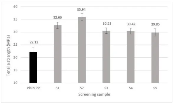
Figure 4.1, Tensile strength of 20wt% harakeke filament under different processing parameters. ... 57
Figure 4.2, Young's modulus of 20wt% harakeke filament under different processing parameters. ... 57
Figure 4.3, Sample S5 showing large pores and fibre pull-out ... 58
Figure 4.4, Sample S2 showing reductions in pore size ... 59 Figure 4.5, S2 sample showing fibre pull out and fibre fracture near the surface 59
Figure 4.7, Tensile strengths of the 3mm composite filaments produced using
pre-consumer PP as a matrix (MPa). ... 61
Figure 4.8, Young's modulus of composites produced using pre-consumer PP as a matrix (MPa). ... 62
Figure 4.9, Influence of fibre content on surface finish ... 63
Figure 4.10, Tensile strength of 3d printed dog bone composite samples ... 64
Figure 4.11, Young's modulus of 3d printed dog bone composite samples ... 65
Figure 4.12, FDM printed dog bone sample showing stress concentration point . 65 Figure 4.13, Tensile strength of 3d printed 1mm pre-consumer filament ... 66
Figure 4.14, Young’s modulus of 3d printed 1mm pre-consumer filament... 67
Figure 4.15, Asymmetrical surface finish of a 30 wt% harakeke dog bone specimen ... 67
Figure 4.16, Tensile strength of composites containing gypsum compared to plain PP ... 69
Figure 4.17, Young's modulus of composites containing gypsum compared to PP ... 69
Figure 4.18, 20 wt% gypsum filament showing particles distributed with gypsum crystal clusters ... 70
Figure 4.19, Small gypsum cluster within 20 wt% gypsum filament ... 71
Figure 4.20, 40 wt% gypsum fracture surface showing partially covered crystal cluster ... 71
Figure 4.21, 50 wt% gypsum fracture surface showing crystal cluster. ... 72
Figure 4.22, Plain polypropylene shrinkage sample ... 73
Figure 4.23, 10 wt% hemp shrinkage sample ... 73
Figure 4.24, 20 wt% hemp shrinkage sample ... 73
Figure 4.25, 30 wt% hemp shrinkage sample ... 73
Figure 4.26, Tensile strength of post-consumer PP/Harakeke and PP/hemp fibre composites (MPa) ... 74
Figure 4.27, Young’s modulus of post-consumer PP/Harakeke composite filament (MPa) ... 75
Figure 4.28, 30 wt% harakeke filament fracture surface showing polyester fibres ... 76
Figure 4.29, 30 wt% harakeke filament showing surface finish and fibre
alignment ... 77 Figure 4.30, 30 wt% harakeke filament aligned fibre beneath the surface ... 77 Figure 4.31, 30 wt% harakeke filament fracture surface showing fibre
alignment and fibre pull out ... 78 Figure 4.32, Polyester fibre adhesion within 30 wt% harakeke filament ... 78 Figure 4.33, Tensile strength comparison between 3mm, dry 1mm and wet
1mm printed hemp filaments... 80 Figure 4.34, Young’s modulus comparison between 3mm, dry 1mm and wet
1mm printed hemp filaments... 80 Figure 4.35, Tensile strength comparison between 3mm, dry 1mm and wet
1mm printed harakeke filaments ... 81 Figure 4.36, Tensile strength comparison between 1mm printed filaments
produced from dried and undried filament ... 81 Figure 4.37, 20 wt% wet harakeke 3mm filament ... 84 Figure 4.38, Fracture surface of 20 wt% harakeke 1mm filament produced with
pre-dried filament ... 85 Figure 4.39, Fracture surface of 20 wt% harakeke 1mm filament produced with
List of Tables
Table 1.1, Comparison of natural fibre properties with those of synthetic fibres
[5-8] ... 6
Table 1.2, Non-renewable energy resources for glass and flax fibre mat (MJ/kg) [11] ... 7
Table 1.3, Processes, materials, advantages and disadvantages of different 3d printing technologies ... 9
Table 2.1, Comparison of fibre content between hemp and harakeke [38] ... 16
Table 2.2, Melting temperatures and densities for different thermoplastics [44-48]... 18
Table 3.1, Gib Plasterboard gypsum board constituents ... 48
Table 3.2, Particle size for recycled gypsum powder ... 48
Table 3.3, Initial filament processing parameters ... 52
Table 3.4, Filament constituent compositions... 52
Table 4.1, Mechanical properties of natural fibre compared to glass fibre reinforced 3d printing filament ... 62
Table 4.2, Shrinkage values for pre-consumer polypropylene composites ... 72
Table 4.3, Comparison of pre-consumer PP/ glass fibre composites with post-consumer PP natural fibre composites ... 75
Table 4.4, Mechanical property comparison for dry and wet printed 1mm filament... 79
Table 4.5, Density of 3mm filament compared to 1mm printed filament... 82
Table 4.6, Comparison of specific strength values for 3mm and 1mm filament .. 83 Table 4.7, Comparison of specific modulus values for 3mm and 1mm filament . 83
Chapter 1:
Introduction
1
Chapter 1
Introduction
1.1
Overview of Polymers and Polymer Recycling
in New Zealand
Polymers are an incredibly diverse (and commonly) durable group of materials that have been utilised in an increasing quantity particularly over the past 100 years. There are many different types of naturally occurring polymers such as wool, cellulose, proteins and DNA, some of which have been used in an engineering context for many years. In addition to natural polymers; there are also many types of synthetic polymers; some of which are known as plastics.
Predominantly derived from petrochemicals, plastics can be readily formed into any solid shape with a wide range of modifiable properties. Due to the low cost and diversity of plastics, many products previously made from more traditional materials such as ceramics or wood are now being made with plastic. However, the durability of plastic makes it difficult to decompose and considerable amounts of waste plastic is accumulating in the environment.
Plastics can be classified into two groups known as thermosets and thermoplastics. Thermosets rely on an irreversible chemical reaction to solidify polymer resin into a desirable form. Thermoplastics consist of long linear chains of monomers that are bonded with one another by weak chemical bonds. When the plastic is heated, these weak bonds are broken and the chains are free to flow allowing the polymer to assume different shapes. Once the molten polymer cools, the bonds reform causing solidification and potential shrinkage.
Thermoplastic materials can be further categorised as either amorphous or semi-crystalline based on the degree of order (crystallinity) within the monomer chains after the polymer has solidified. The monomer chains within an amorphous polymer will solidify into a random pattern displaying no evidence of crystallinity.
The monomer chains in a semi-crystalline polymer however, will contain both crystalline and amorphous regions. The crystalline regions within semi-crystalline polymers are the primary cause of shrinkage or warping within these polymers on solidification. Thermoplastics can be heated and reformed (recycled) multiple times, however, every time thermoplastics are recycled the linear chains can become shorter having an adverse effect on the properties of the finished material [1; 2]. When heat is applied to a thermoset however, the polymer simply burns making it difficult to recycle.
It is estimated that plastics can take between 450 – 1000 years to decompose, meaning that apart from burnt and plastics, virtually every piece ever made is still in existence. Increased public awareness of the strain that waste plastics are having on the environment has made it a marketing advantage for companies to use recycled plastics [3]. This has led to an increase in collection and processing systems throughout New Zealand. The current plastic recycling method can be broken down into the following five steps:
• Collection of bulk recycled plastics.
• Sorting of plastics into individual plastic types. • Cleaning and removal of contaminants.
• Chipping or resizing into small pieces.
• Extrusion into manufacturing pellets for resale.
Of the five steps above each has associated costs that affect the viability of different waste plastic streams. Attempts to standardise the sorting process have led to the numbers system shown in Figure 1. The system assigns a number and an abbreviated title for each type of plastic. This information is displayed on most plastic products making it much easier to distinguish the different types. The first six numbers are the most commonly used and make up the majority of house hold consumable plastics. The number seven is used when the plastic does not fit into any of these categories and could be any one of the hundreds of types.
The recycled plastics industry is entirely market driven; therefore if no market has been identified or if the market value is too low, the collected plastics are sent to landfill. This is currently happening in most parts of New Zealand with plastics 3,4,6 and 7, mainly because the supply is insufficient to warrant further processing and compete with virgin plastic prices. Manufacturers of plastic products generally prefer using virgin plastics to reduce the risk of defects and contamination. This causes the sales of recycled plastic granules to fluctuate in accordance with the price of virgin plastics, which reflects the current price of crude oil.
Polypropylene (PP) which is represented by the number 5 in the recycling system, is a thermoplastic polymer derived from propene, a relatively inexpensive by-product of the oil refining process. As propene is inexpensive, virgin PP is relatively cheap when compared to other virgin materials which leads to a low market price for recycled PP (varies between$100-$200 per tonne). Given the market dependence on recycled polymer viability and the manufacturers preference for virgin material, the market price for recycled polypropylene varies between $100 -$200 per tonne. Despite the high quantity of PP being used in consumer products, the low market value often does not warrant the cost of collection and sorting resulting in the polymer going to landfill.
Properties of recycled plastics can be modified and improved in a number of ways. The most common of which is to add a certain percentage of virgin material to the recycled mix. This method increases the average linear chain length, therefore increasing the properties of the material as a whole. Another method of improving the mechanical properties is to blend in other additives such as fibre to form composite materials.
1.2
Overview of Composite Materials
A composite is a combination of two or more materials where the properties of each complement one another to form a superior result. This allows the properties of the composite material to be tailored specifically to suit the application. Composite materials have been in use for thousands of years. Ancient Egyptians used a combination of wood, water buffalo horn, sinew and glue to construct archery bows superior to wooden bows; concrete that was extensively used to build roman structures which still stand today, is a combination of volcanic ash, water, aggregate, and mortar. The significant benefits of modern composites have allowed them to steadily replace traditional materials in many different industries.
Broadly speaking composites can be categorised into five main groups namely: ceramic matrix composites, metal matrix composites, intermetallic composites, carbon – carbon composites and polymer matrix composites [4]. Polymer matrix composites offer advantages such as lightweight, ability to fabricate complex shapes and good mechanical properties along the direction of reinforcement.
Fibres of various types are often used for reinforcement in composite materials because they are strong, light weight and readily available. Fibre reinforced composites (FRC) can be manufactured with either short or continuous fibres each with associated advantages and disadvantages. Continuous fibre reinforced composites are often more difficult and time consuming to accurately manufacture than short fibre composites, but yield superior mechanical properties. These composites are often used in high performance applications; for example, in the aerospace industry various metals are being replaced with carbon fibre composites which, because of the strength of carbon, can occupy a smaller space with higher mechanical properties.
The mechanical properties of a FRC are largely controlled by the selection of fibre and matrix constituents but are also influenced by the interfacial bond strength between the fibre and the matrix. A weak bond between the fibre and the matrix will mean poor stress transfer to the fibres which could potentially result in lower mechanical properties than that of the unreinforced polymer.
This research focuses on the development of short fibre reinforced thermoplastic composites. Thermoplastic composites combine the enhanced mechanical properties of composite with the versatility and ease of moulding of thermoplastics. The choice of which thermoplastic to use as a matrix material will largely affect the end use capabilities for the material. For example, using poly vinyl chloride (PVC) as a matrix material would mean the composite would have improved ultra violet stability whereas using PLA would mean the composite could biodegrade more readily. Some key factors that influence the choice of fibre reinforcement could be cost, performance, weight or recyclability. Synthetic fibres tend to be difficult to recycle due to their brittle nature. If minimal effects on the environment are of high priority then it could be better to choose a non-mineral natural fibre.
1.3
Natural Fibre Reinforced Composites
Natural fibre composites offer a more sustainable alternative to synthetic counterparts and an area of growing interest in composites engineering. Synthetic fibres such as carbon and aramid have numerous benefits which make them an attractive option if remarkable properties are necessary. However, synthetic fibres can be costly to fabricate as well as hard wearing on moulds and production machinery.
Glass fibre is the most widely used of synthetic fibre for composite manufacturing owing to its relatively low cost, versatility and high strength. However, when glass fibre composites fracture in service, there will often be an ‘unfriendly’ or abrasive fracture surface, which can be pose significant health risks. In addition to health risks, the brittle nature of the fibre can cause fibre length reductions during processing which leads to significant reductions in mechanical properties. The incineration of these composites is impractical, as the mineral content is often upwards of 50 wt% which can cause blockages in furnaces and they generally go to landfill.
Many different types of natural fibre have been investigated for the purpose of finding a more sustainable alternative to glass fibre. Natural fibres not only have the potential to reduce adverse effects on the environment, but they can potentially do so at a lower cost than glass.
The properties of various natural fibres compared with various synthetic fibre are shown in Table 1.1. Although the tensile strength and stiffness of synthetic fibres is certainly higher, the low density of natural fibre allows compensation by means of higher fibre loading to produce a composite of the comparable weight.
Table 1.1, Comparison of natural fibre properties with those of synthetic fibres [5-8] Natural Fibre Fibre density (kg/m3) Tensile strength (MPa) Young's Modulus (GPa) Elongation at break (%) Flax 1500 345-1000 27.6 2.7 - 3.2 Hemp 1250 550-1110 30 - 60 1.6 Jute 1300 - 1400 393 - 773 13.0 - 26.5 1.2 - 1.5 Kenaf 1500 930 53 1.6 Ramie 1500 400 - 938 61.4 - 128 1.2 - 3.8 Abaca 1500 400 12 3.0 - 10 Curaua 1400 500 - 1150 11.8 3.7 - 4.3 Pineapple 1440 413 - 1627 34.5 - 82.5 1.6 Sisal 1400 468 - 640 9.4 - 22.0 3.0 - 7.0 Coir 1100 131 - 175 4.0 - 6.0 15.0 - 40 Cotton 1500 - 1600 287 - 800 5.5 - 12.6 7.0 - 8.0 Oil palm 700 - 1550 248 3.2 25 Bagasse 1250 290 17 Bamboo 600 - 1100 140 - 230 11.0 - 17.0 Harakeke 1270 - 1520 440-990 32.09 4.58 Synthetic Aramid 1400 3000 - 3150 63.0 - 67.0 3.3 - 3.7 Carbon 1700 4000 230 - 240 1.4 - 1.8 E-glass 2500 2000 - 3500 70 2.5 S-glass 2500 4570 86 2.8
The recyclability of natural fibre composites after service is yet another compelling reason for the replacement of glass fibre. Recycling involves the mechanical and thermal degradation of both the matrix and reinforcing fibres. Cellulose based natural fibres such as hemp or harakeke are durable enough to largely withstand the shear forces involved in reprocessing. This means they can be recycled several
Cellulose based fibres occur naturally as a result of photosynthesis and require very little additional energy to assist in their growth. Synthetic fibres on the other hand, often need to be processed from raw materials requiring significant amounts of additional energy. A study conducted by Joshi et al compared the energy required in the production of glass and flax fibre composites shown in Table .below1.2
Table 1.2, Non-renewable energy resources for glass and flax fibre mat (MJ/kg) [11]
Glass fibre mat Flax fibre mat
Raw materials 1.7 Seed production 0.05
Mixture 1 Fertilizers 1
Transport 1.6 Transport 0.9 Melting 21.5 Cultivation 2.0 Spinning 5.9 Fibre separation 2.7 Mat production 23.0 Mat production 2.9
Total 54.7 Total 9.55
One of the main factors that restrict the wide spread application of natural fibre composites is the variability in both their physical and mechanical properties. The wide range of strength, stiffness and fibre dimensions found from plant to plant make it challenging to accurately predict the performance of the resulting composites. Without additional modification (chemical or otherwise), natural fibres are inherently hydrophilic and will absorb much more water than their synthetic counterparts. Water absorption can result in dimensional instability and a reduction in mechanical properties.
Mineral based synthetic have a high resistance to heat before degradation. Natural fibres, however, begin to thermally degrade at around 190 o C. This can restrict the potential matrix materials for composite fabrication depending on the melting temperature. For example polyethylene terephthalate (PET) has a melting temperature of approximately 250o C which could lead to significant natural fibre
degradation in processing if it were used as a matrix material.
1.4
The 3d Printing Industry and The Opportunities
For Enhanced Materials
Almost 30 years since its conception, additive manufacturing also called 3D printing, has gradually overcome its niche applications and is revolutionising all manner of practices within the manufacturing industry [12]. To produce a component utilising this technology, an accurate model must be generated using computer aided design software. The virtual model is then incrementally divided into layers within the x-y plane before sending to the printer. The printer then proceeds to either deposit or solidify material in the exact shape of each layer until the sum of layers adds to make the entire part. The efficiency of this process minimises consumption of raw material by almost 75%, leading to a reduction in carbon footprint, whilst attaining a high level of geometric accuracy [12; 13].
Corresponding to the increased interest in 3d printing technologies, there has been a substantial increase in the total market value of the additive manufacturing industry. Incorporating machine sales, materials and associated services, the market valuation was estimated to be $7.8 billion USD in 2014. This sector is forecasted to expand at an annual rate of around 35%, with an expected market valuation in excess of $21.2 billion USD in 2020. Household consumers constituted 91.6% of machine sales in 2014, whilst industrial consumers accounted for the remaining 8.4% [14]. Growth in the industry has been largely attributed to the further development of stronger and cheaper materials with polymeric materials occupying over 80% of the market [15].
There are several different types of 3d printing techniques and more are being developed as the technology progresses. Modern 3d printers are capable of printing a wide range of materials from plastics to ceramics, however, for the purposes of this work we are primarily concerned with thermoplastic 3d printers which are the most economical and most often used. Currently, the two most common methods that print with thermoplastic materials are selective laser sintering and fused deposition modelling Table .1.3
Table 1.3, Processes, materials, advantages and disadvantages of different 3d printing technologies
Technology Process Typical materials Advantages Disadvantages
Fused deposition modelling Material extrusion Thermoplastics, composites Complex
geometries, low cost printers and materials Poor surface finish compared to other methods, relatively slow build time. Selective laser sintering Powder bed fusion Thermoplastics, Paper, metal, glass, ceramic, composites High speed, no support material required, high heat and temperature resistance Accuracy limited to powder particle size, rough surface finish
Fused deposition modelling (FDM) is one of the cheapest and most widely adapted methods of 3d printing to date. In this process, a thermoplastic filament is melted and extruded through a circular nozzle. The movement of the nozzle is controlled by using a 3-axis system allowing the molten plastic to be deposited onto a print bed. FDM allows parts of any geometry to be constructed in layers, through the successive deposition of molten material. Thermoplastics are the preferred filament material, although a wide range of materials, including cement and composites, are compatible with the FDM process [16; 17]. The success of FDM has largely been accredited to its simplicity, accuracy and affordability, which has enabled the general public to become acquainted with additive manufacturing.
The most popular thermoplastic materials used in FDM are acrylonitrile butadiene styrene (ABS) and polylactic acid (PLA). One quality that these materials have in common is that they are amorphous polymers. Amorphous polymers are used in FDM primarily because of the low degree of shrinkage relative to the semi-crystalline alternatives. Any shrinkage or warping of the polymer layers produced through FDM will greatly affect the quality of the printed component. Therefore, when using semi-crystalline polymers such as polypropylene, it is of paramount importance to limit shrinkage.
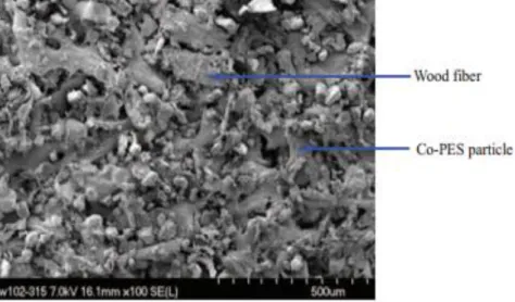
Introducing fibres or particles into polymers not only reduces shrinkage [18-20], but also improves the aesthetics and mechanical performance. Laywood is a brand of wood fibre reinforced composite FDM filament that contains up to 40 wt% recycled wood fibre in a PLA matrix. Since it was released in 2013 laywood has seen significant popularity amongst 3d printing communities and it has distributers in 11 countries. Laywood filament has been marketed more for its aesthetics, producing a textured finish of which the shade can be darkened by increasing the temperature and burning the fibres slightly.
When strength and performance are important, composite filaments have been developed which incorporate a range of different synthetic fibres. Tekinelp et al [21] found that the addition of short carbon fibres to ABS polymer increased the tensile strength and Young’s modulus by 115 and 700% respectively. There is no clear evidence that this study has been commercialised into marketable filament; however, there are filaments available on the market such as Proto Pasta [22] and 3dxtech [23] that commercially produce carbon fibre composite filaments.
1.5
Research Objectives
The aim of this research was to fabricate a composite 3d printing filament from recycled polypropylene with enhanced mechanical properties and increased dimensional stability.
To these ends, the following were investigated:
Creating dimensionally consistent filament by controlling extrusion parameters and spooling techniques;
Investigating the effect on polymer shrinkage with varying fibre and gypsum powder content;
Optimising fibre reinforcement by altering coupling agent particle size, fibre drying temperature and compounding cycles;
The influence of fibre and gypsum content on tensile properties.
Chapter 2:
2
Chapter 2
Literature Review
2.1
Natural Fibres
Figure 2.1, Types of natural fibres
Natural fibres are defined as hair like solids that can be directly obtained from an animal, vegetable or mineral source as shown in Figure 2.1. Renewable natural fibres are those that can be replenished in a predictable time period and exclude mineral natural fibres. Renewable natural fibres are used as a low cost alternative to synthetic fibres due to their reasonable mechanical properties, biodegradability, low density and the fact that they can be readily reproduced requiring little energy [5].
In plants generally, the bast and leaf fibres are used as mechanical support (holding up the stem and leaves respectively). Bast fibres surround the core of the plant stem and are found on the inner surface of the bark (phloem) [8]. Leaf fibres come from the structural component of the leaf such as the middle support in abaca or the leaf itself in the case of Harakeke [7], [6]. The disadvantages associated with using organic as opposed to synthetic fibres are high moisture absorption, low level of geometrical consistency, poor adhesion with matrices and low thermal stability [24].
2.2
Plant Based Natural Fibre Constituents
Figure 2.2, Composition of natural fibres
Plants can be considered to be excellent examples of naturally occurring composite materials. They consist of multiple layers of different constituents collectively determining the properties of the plant as a whole Figure 2.2 [5]. The majority of the stiffness and strength come from the earth’s most abundant natural polymer known as cellulose. The cell walls of a plant consist of reinforcing oriented semi-crystalline cellulose micro fibrils which are embedded in a mainly two phase (lignin-hemicellulose) amorphous matrix [8]. Contained within these micro fibrils is where the cellulose chains can be found.
2.2.1
Cellulose
Generally most natural cellulosic fibres contain 60–70% cellulose which is primarily composed of C, H, and O2. The general formula for cellulose is
(C6H10O5)n and the structure of the glucose monomer is shown in brackets in Figure
2.3. Molecular chains of cellulose, composed of thousands of covalently bonded glucose monomers are oriented in the fibre direction. There are three hydroxyl groups contained within each repeating glucose unit. These enable the cellulose to form strong hydrogen bonds with its own chains to form micro fibrils [25].
Cellulose micro fibrils are wound around the cell wall, at an angle with respect to the fibre axis (Figure 2.4).This angle largely dictates the transmission of the force to the cellulose reinforcement. This explains for example, the higher stiffness and strength of hemp (~40 angle) as opposed to cotton (~25-35o angle) regardless of the fact that cotton has approximately 30% more cellulose than hemp [8] and [27]. This has a lot to do with the function of the fibre in its natural setting. Hemp fibres from the stalk are required to be strong in order to support the 2-4.5m plant, while cotton fibres come from the flower and are not there to serve as mechanical reinforcement.
Cellulose comprises of both crystalline and amorphous regions, depending on whether the cellulose chains are held in a highly ordered (crystalline) structure due to intermolecular hydrogen bonding. Crystalline and amorphous cellulose have significantly different mechanical properties. The tensile stiffness of
crystalline cellulose can be up to 15 times more than that of amorphous cellulose [28].
Figure 2.3, Chemical structure of cellulose [26]
Figure 2.4, Microstructure of the cotton fibre showing the angle of fibrils with respect to the fibre axis [27] .
In addition to cellulose there are three other main constituents contained within plants (hemicellulose, lignin and pectin). The relative amounts of these are known to vary between different types of plant fibre [29]. Individually these constituents have poor tensile properties when compared to cellulose. These constituents do contribute to the rigidity and compressive strength of the plant however, their primary function is to serve more as a matrix material.
2.2.2
Hemicellulose
The second most abundant constituent within natural cellulosic fibres is generally hemicellulose. Despite the misleading name, hemicellulose is not a form of cellulose but belongs to a group of polysaccharides that are linked together in short branching chains [8]. Hemicellulose has very poor mechanical properties and functions more as a coupling agent between cellulose and lignin. The moisture absorption and biodegradability inherent in natural fibre is attributed predominantly to hemicellulose [30].
2.2.3
Lignin
Lignin is a totally amorphous three dimensional polymer which provides compressive strength to the very small micro fibrils. Lignin also serves as a moisture barrier to the absorbent hemicellulose. Although it makes reasonable contributions to the rigidity of a plant, lignin is undesirable for use in composites and is therefore one of the constituents commonly removed [29].
2.2.4
Pectin
Pectin is a carbohydrate polymer found within bast fibres and is useful for providing flexibility in plants. Although present in most natural fibres, pectin is a minor constituent accounting for 0.9% in both flax and hemp fibres [31]. Separation of fibre bundles from surrounding cells of the stem can be achieved with effective removal of pectin material [32]
2.3
Hemp Fibre
Hemp is a lignocellulosic bast fibre, which comes from the Cannabis Sativa plant species. Depending on the climate, hemp grows quickly with little difficulty producing a crop with the high yield of 0.25-1.4 kg/m2 of dry stem per season [33] Due to its impressive stiffness and strength, hemp fibre has a long history of applications dating back as far as 6,000 years. Earlier applications of hemp fibre took advantage of its long fibres to manufacture robust rope and textiles. Modern day applications have been hindered due the plants similarities between marijuana, an illegal plant from the same species used as a recreational drug. However, extensive research into the plants potential has helped to reform laws and make it to easier to access. The fibre is still used in the textile industry, but the inclusion of hemp fibre into modern composites is a more wide spread industrial application. Automotive companies such as Ford, Audi and BMW all have components such as door panels, boot linings and parcel trays made from hemp fibre composites [34].
2.4
Harakeke Fibre
Harakeke, otherwise known as Phormium tenax, is a plant native to New Zealand consisting of strong fibre harvested from the leaf. In the early 1920s it was a significant export for the country and used to produce rope, clothing and sacks [35]. The use of synthetic fibres have since replaced harakeke and the plant is mainly used for crafts. Although the plant it is similar in appearance, it is not biologically related to flax and has not been as extensively studied for use in composite materials [36]. The time it takes to grow a harakeke plant to full maturity is 7 years and it has been documented that the mechanical properties are highly dependent on the environment [37]. Whilst hemp fibre has been more extensively studied for applications into composite materials, harakeke has demonstrated similar mechanical properties and is a much finer fibre. A comparison of fibre content between each species can be seen in Table 2.1 below.
Table 2.1, Comparison of fibre content between hemp and harakeke [38]
Fibre Cellulose (%) Hemicellulose (%) Lignin (%) Pectin (%) Hemp 55 – 78.3 10.7 – 22.4 2.9 - 13 0.8 – 1.6 Harakeke 45.1 - 55 27.3 – 30.1 7.8 – 11.2 0.7
2.5
Gypsum Powder
Gypsum is an abundant mineral which is otherwise known as calcium sulfate dihydrate. By weight, unprocessed gypsum contains approximately 21% water which is in crystalline form so the material appears to be dry. When heated to temperatures exceeding 100°C, crystalline water turns gaseous and evaporates. Pulverised gypsum that has had 75% of its moisture removed is known as plaster of paris or stucco in the construction industry. This can then be combined with liquid water and moulded into shapes and upon drying the reconstituted gypsum will regain its solid form in the shape of the mould [39]. The versatility of gypsum has seen it used extensively for decoration and construction in applications as far back as ancient Egypt to its most common modern application in wallboard materials [40]. The wide spread application of gypsum in the building industry comes as a result of the minerals good fire resistance, thermal and sound isolation properties.
The microstructure of gypsum powder consists of needle like crystals in cluster form as shown in (Figure 2.5). Mechanical size reduction of gypsum powder results in the brittle fracture of crystals and separation into smaller clusters [41].
Figure 2.5, SEM image of needle shaped gypsum microstructure [41]
2.6
Thermoplastic Matrices
When it comes to matrix material selection, thermoplastics are becoming an increasingly compelling choice. Benefits of thermoplastic matrices can include infinite shelf life, low moisture absorption and mechanical properties specific to the application [10]. Generally, processing natural fibre composites at temperatures exceeding 200°C will result in lignocellulose degradation which could have adverse effects on mechanical properties [42]. Thermoplastic matrix materials selected for fabricating natural fibre composites must therefore be selected with processing temperature as the primary concern. A comparison of different commodity thermoplastics and their melting temperatures can be seen in Table 2.2 below. The relatively low melting temperature of polypropylene for example, would make it a more favourable choice as a matrix material than polyethylene terephthalate or polystyrene.
To successfully fabricate a light weight composite material it is advantageous to choose a matrix with a low density. Comparing the density values in Table 2.2 it can be seen that either polypropylene or low density polyethylene would make a good choice in this regard. The contributions of the polymer matrix to the overall mechanical properties are found to be increasingly less significant in fibre composites with fibre content in excess of 50 wt% [43]. Therefore, for strong light weight applications, low density is of higher significance than mechanical properties in terms of matrix material selection.
Table 2.2, Melting temperatures and densities for different thermoplastics [44-48]
Type of thermoplastic Melting temperature (°C) Density (g/cm3)
Polypropylene 150 - 160 0.935 High density polyethylene 120 -180 0.956 Low density polyethylene 105 - 115 0.923 Polyethylene terephthalate 235 - 260 1.38 Polystyrene 210 - 245 1.05
2.6.1
Polypropylene
Polypropylene (PP) is a semi-crystalline polymer that is produced through the polymerisation of propylene monomers in the presence of a Ziegler-Natta catalyst [49]. PP is derived from propene, which is a by-product of the oil refining process. Much like polyethylene (PE), PP is a linear hydrocarbon polymer (Figure 2.6), and shares several similarities with the former. Factors such as molecular weight and distribution, along with the variety and quantity of copolymerising monomer, will influence the final physical and processing characteristics of PP [49-51]
Figure 2.6, Molecular composition of polypropylene [52].
The versatility of polypropylene has allowed it to be adopted for a wide range of industrial applications. Low cost, reasonable thermal stability and simplicity of reprocessing are several of the attributes that are gradually increasing the global demand for PP [50; 53; 54] . PP typically has a density of 90 g/cm3, a glass transition
temperature of -10 oC, and a melting point of 165 oC [51]. These properties demonstrate that PP is compatible with natural fibre reinforcement, although chemical treatment of fibres, and the addition of coupling agents are required to improve interfacial adhesion [49] . The low moisture absorption properties of PP are beneficial for minimising the effects of water absorption, since water can have an adverse effect on the fibre/matrix interface of composites [51] . The mechanical characteristics of PP closely resemble some engineering thermoplastics, and are essentially identical with the addition of reinforcement. With a number of favourable attributes, along with being an existing material for additive manufacturing filament, PP is a suitable candidate for further investigation with natural fibre reinforcement.
2.6.2
Polymer Shrinkage
Unlike pure amorphous plastics, during solidification the molecular chains of some thermoplastic materials arrange in periodic patterns producing crystalline regions.
This crystallinity occurs in the form of folding chains known as lamellae as shown schematically in Figure 2.7below. Factors such as entanglement within polymer chains and differences in molecular weight within the polymer are known to limit the degree of crystallisation that will occur within a semi-crystalline polymer [55] .
The regions of the polymer that cannot crystallise remain amorphous and have different physical properties than crystalline regions [56]. As a polymer melt is allowed to cool and solidify, the contracting forces caused by crystallisation can result in polymer shrinkage and warping. This is the reason why polymers with higher crystallinity experience a higher degree of shrinkage when compared to amorphous polymers [18; 57]. Although polymer shrinkage can be attributed to several factors such as non-uniform cooling rates, density changes and temperature, the degree of crystallinity is an important factor to consider when it comes to shrinkage in semi-crystalline polymers.
Another factor that has considerable influence on polymer shrinkage and is particularly relevant to this research is the content of filler material. Generally, the addition of particulate or fibre fillers will reduce the shrinkage effects within the polymer [18-20]. This can be understood intuitively by considering that if the filler material is dimensionally stable, then including it within the polymer will reduce the amount of less dimensionally stable polymer and therefore the overall shrinkage. Filler material may also interfere with the crystallisation process by creating physical barriers between lamellae regions [58].
Tan et al. [20] studied the effects on volumetric shrinkage reduction with the addition of short coir fibres in a polypropylene matrix. The inclusion of 40 wt% fibre corresponded to a reduction in volumetric shrinkage from 1.3 to 0.6%. Hakimain et al studied the influence of glass fibre reinforcement on shrinkage and achieved a 29% reduction with the addition of 30 wt% fibre glass. The study also showed that the shrinkage was lower when the fibre orientation was high.
2.6.3
Polymer Rheology
The most important flow property of a polymer or polymer composite is viscosity which describes the resistance to shearing. As the molten material is forced to move through a cavity there is a large amount of shearing occurring, much like a deck of cards sliding over one another, referred to as laminar flow. This results in the outer walls of the polymer moving much slower than the interior as indicated in Error! R eference source not found. [59].
Figure 2.8, Laminar flow of polymer through cylindrical die [59]
These shear forces cause the polymer to orientate itself in the flow direction and internal strains will build up. These strains recover as it exits the die which can potentially result in a swelling effect known as die swell. The extent of die swell is largely dependent on the materials ability to store deformation energy. When a polymer is extruded through a short capillary, the internal stresses resulting from elongation at the die entrance will have the greatest effect on die swell. When the polymer is extruded through a long die (L/D > 30) the stresses caused by entrance effects have time to relax out and die swell is predominantly caused by shear forces generated in the die itself [60; 61].
Sharkskin is a term used to describe surface undulations which are thought to originate near the exit of the die and result from a stick-slip phenomena (Figure 2.9). When the shear stress between the polymer and the walls of the die reaches a critical level, the skin of the extrudate will begin to rupture in a quasi-periodical manor [62; 63]. Methods of reducing sharksnin include heating the die and slightly modifying the die to decrease wall shear or modifying exit angle to avoid stick [61; 62].
The addition of filler materials such as fibre or particles can change the rheology significantly depending on a number of factors. These factors include filler shape, size, concentration and the extent of any interactions between the constituents. In general, increased filler content will result in an increased viscosity and a decrease in die swell. [64]. A study conducted by Khalina et al [65]investigated melt flow and viscosity behaviour of 42 wt% kenaf/polypropylene composites fabricated with varying fibre sizes of 250, 450 and 850 micron. The results show a sharp decrease in melt viscosity for all materials with an increasing shear rate. The increased fibre length gave rise to an increase in viscosity which complimented the theory that higher specific area of additives tend to increase viscosity.
2.7
Natural Fibre Composites and the Factors
Influencing Effective Fabrication
Composite materials consist of multiple phases in which the phase distribution and geometry have been deliberately tailored to optimise one or more properties [66]. The use of natural fibres to reinforce materials dates back for thousands of years with the ancient Egyptians using straw to enhance the properties of clay[67]. What are considered to be modern composites only started emerging and gaining momentum during World War 2. This was when glass fibre was combined with thermoset plastics for various military applications such as aircraft and communications equipment [68]. The two phases that make up a natural fibre composite are either a cellulose, protein or mineral based fibre and the matrix. The main purpose of the matrix is to transfer the force experienced on the component to the fibre reinforcement which is generally stronger than the matrix [69]. There are a number of factors outlined in this section that influence the overall properties of a natural fibre composite material.
2.7.1
Fibre Orientation
The orientation of fibres is an important factor that influences strength and other properties in fibre-reinforced composites. The most effective reinforcement is generally achieved when the fibres are oriented longitudinally to the direction of the applied load [70]. Figure 2.10 represents (a) continuous and aligned, (b) discontinuous and aligned, and (c) randomly orientated modes of fibre arrangement.
In practice, it is very difficult to achieve universal short fibre alignment in a single direction. Many natural fibre composite materials will display largely isotropic properties, due to dispersed and randomly orientated fibres. Several processing techniques, such as injection moulding and extrusion, allow for moderate improvement of fibre alignment in the flow direction. This can be attributed to the shear forces from die walls forcing fibres to align in the flow direction [71].
2.7.2
Fibre Aspect Ratio
The length to diameter ratio of a fibre is known as the fibre aspect ratio and is of critical importance when trying to optimise composite properties. The mechanical properties of a fibre reinforced composite are heavily influenced by the extent of applied load transfer from the matrix phase to the fibres [70] . This load transference is dependent on the degree of interfacial bonding between the fibre and matrix phases. When a tensile load is applied to a fibre composite, the load is transferred to the reinforcing fibres via shear forces at the fibre matrix interface. Increasing the fibre surface area that is in contact with the matrix increases the shear forces resulting in better reinforcement of the composite. The critical fibre aspect ratio is the minimum fibre aspect ratio in which the maximum allowable fibre stress can be achieved for a given load. The critical fibre aspect ratio can be calculated using equation 2.1 below.
𝑙𝑐
𝑑
=
𝜎𝑓
2𝜏
Where 𝑙𝑐 is the critical fibre length, 𝜎𝑓 is the tensile strength of the fibres, 𝑑 is the fibre diameter and 𝜏 is the interfacial shear stress [70; 72]. Increasing the fibre length will generally lead to an increase in mechanical properties of the composite. The advantages gained with increasing length will eventually plateau once a threshold is passed, offering no further improvement in mechanical properties [72] .
2.7.3
Moisture Absorption
In general, as the volume of natural fibre in the composite increases, the rate of moisture absorption as well as the total moisture the material can retain will also increase. The grey squares shown in Figure 2.11 represent fibres distributed within a white matrix. With lower fibre content shown in Figure 2.11a, the fibres on the outer layer of the composite will absorb moisture up until they reach saturation point at which point no more water will be absorbed. In the case of a higher fibre content (Figure 2.11b) it is more likely that the fibres will be in contact with one another in the form of bundles [73]. This will allow water to be absorbed through neighbouring fibres further into the composite material and the composite will therefore retain more water.
Figure 2.11, Low and high fibre volumes distributed in matrix material [73]
Fortunately, moisture absorption can be controlled to an extent through chemical treatment of the natural fibre prior to processing. The incorporation of a coupling agent will also increase the interaction of the fibre and matrix phases, improving the moisture resistance of a composite [74; 75] .
2.7.4
Thermal Stability
Cellulose based fibres are generally known to thermally degrade at temperatures exceeding 200 oC, although there have been cases where degradation onset takes place as low as 160 - 190 oC [76; 77]. This restricts the addition of natural fibre reinforcement to matrix materials with low melting temperatures. Chemical modification such as alkalai treatment has been found to increase the fibres resistance to thermal degradation by removing lignocellulose and increasing the
A study conducted by Talla et al [79] investigated the extent of thermal degradation of alkilai treated hemp fibre in a PET matrix subjected to a range of temperatures and heating rates. It was found that the heating rate 10 oC could be used to minimise the effects of fibre degredation.
2.7.5
Methods of Improving Interfacial Adhesion between
fibre and matrix
The mechanical properties of natural fibre composite materials are often limited due to poor adhesion between the fibre and matrix [66]. However, the interfacial adhesion can be improved by making modifications to the fibres, the matrix or both the fibres and the matrix. Two common methods used in natural fibre composites are the addition of chemical coupling agents to matrix materials and chemical surface treatments of the fibre. A coupling agent can be defined as a compound which provides a chemical bond between two dissimilar materials, usually inorganic and organic materials [80]. Generally coupling agents yield two primary functions: The first is to react with the surface of the fibre and the second is to react with functional groups of the polymer matrix [66].
2.7.5.1
Alkali Fibre Treatment
Improvements in fibre strength can be achieved by using alkali treatment to remove amorphous non-cellulosic substances while also increasing the percentage crystallinity and molecular alignment of cellulose [81]. The main variables concerning the success of the alkali treatment are: chemical concentration, temperature and time spent in the digestion process [82]. Research conducted by Islam [81] investigated the effects of alkalai treatment of hemp fibre by testing 16 different combinations of NaOH and Na2SO3 concentration, temperature and
treatment time. It was concluded that 5 wt% NaOH, 2 wt% Na2SO3 and 120oC for
60 minutes was the most favourable combination producing the best fibre qualities of the study. These include the removal of non-cellulosic constituents, fibre separation from bundles, increased surface roughness and increased crystalline cellulose.
2.7.5.2
MAPP Coupling Agent
Maleic anhydride grafted polypropylene (MAPP), or maleated polypropylene, is among the most popular coupling agents considered specifically for natural fibre polypropylene composites. The use of MAPP has encountered notable success in optimising the mechanical performance of composites [83] . A study conducted by Mutjet et al [80] used MAPP coupling agent, at 4% wt/wt with respect to varying hemp fibre volume fraction for an injected moulded hemp fibre polypropylene composite. At 40 wt% fibre and 1.6 wt% MAPP, the ultimate tensile strength (𝜎𝑡) and flexural strength (𝜎𝑓) increased by 49% and 38% respectively, relative to the composite without coupling agent. A similar investigation carried out by El-Sabbagh [83] , where MAPP content was varied with respect to fibre volume fraction. The experiment was not restricted to just hemp fibres, as flax and sisal reinforced polypropylene composites were also evaluated. The optimum MAPP to fibre ratio was determined to be within 10% and 13.3% for all three fibre species, as the maximum increase in stiffness, strength and impact properties were observed at those compositions. As shown in Figure 2.12, improvements of 66.1% and 60.1% for 50 wt% flax, and 28.5% and 39.5% wt% hemp, were observed for strength and impact properties respectively with optimum MAPP: NF ratios. Both scenarios clearly demonstrated significant increases in mechanical properties with ideal MAPP concentration [83] .
Figure 2.12, Improvement in mechanical properties with 30 wt% fibre (left) and 50 wt% fibre (right) when combined with MAPP coupling agent
2.7.6
Fibre Volume Fraction
A critical factor necessary for determining optimal composite properties is the amount of reinforcing fibre contained within the material. Many studies have shown that increasing fibre content corresponds to an increase in mechanical properties, particularly stiffness and tensile strength [10; 84-86]. However, there is a point where the benefits gained from additional fibre peak and begin to decline. Experiments conducted by Ku et al with varying content of kenaf fibre in polypropylene showed increased tensile strength with fibre loadings up to 40wt% before a decline was observed [87]. Nishino et al showed similar results when using kenaf fibre in a PLA matrix, the relationship between fibre content, Young’s modulus and tensile strength can be seen in Figure 2.13 below. The decline in tensile strength with excessive fibre loading could be attributed to increased fibre-fibre and fibre-fibre-equipment contact leading a reduction in fibre-fibre length and fibre-fibre efficiency. These increased solid-liquid interactions generally increase the viscosity of molten/liquid composites which can effect various processing parameters such as extrusion speed and injection mould complexity.
Figure 2.13, Effect of increased fibre loading on Young’s modulus and tensile strength of kenaf/PLA composites [88]
2.8
Particle Reinforced Thermoplastic Composites
Particle reinforced composites are a broad range of materials which offer enhanced material properties and relative ease of processing. Advantages of particle composites include increased hardness, thermal stability, shrinkage resistance and lower cost. Some filler materials are also known to enhance mechanical properties such as tensile strength and stiffness, however, these enhancements are small relative to fibre reinforcment [89]. Factors such as moisture absorption, interfacial adhesion and filler volume fraction are applicable to both particle and fibre composites.
Kim et al [90] investigated the effects of shrinkage in the injection moulding
process with increasing talc particle content with talc/PET composites. Experimental results show a clear correlation between talc content reductions in shrinkage as shown in Figure 2.14 below. It was also observed that talc particles of a smaller size were found to be more effective in terms of shrinkage reduction. This was attributed to the increased interfacial area between polymer and talc particles. Particle reinforcement could offer a low cost method of achieving shrinkage reduction in 3d printed components.
Figure 2.14, Correlation between talc content and shrinkage for talc/PET composites [90]
2.9
Processing of Short-Fibre Reinforced
Composites
2.9.1
Extrusion
Polymer composite extrusion is the process of heating and melting the polymer/fibre blend to a workable temperature and forcing the mixture through a small hole or die of the desired shape. The two main types of extruder are twin screw extruders and single screw extruders [91]. The single screw extruder uses screw shaped rod which is concealed inside a heated chamber to force the material through the chamber and out through the die. The twin screw extruder uses the exact same principle but uses two screws in various configurations and rotation directions customised for improved feeding, melting, mixing and material flow [92].
Figure 2.15, Twin extrusion screw set up including mixing and feeding regions [93].
Some example screw configurations for counter and co-rotating twin screw extruders are shown in Figure 2.15.Generally the twin screw extruder is better for achieving homogenous fibre distribution and improved fibre wetting compared with single screw extruders [91]. However, the different sections for mixing and the shear forces caused between the two screws can cause damage or decrease the length of the fibres and therefore reduce the reinforcement effect.
Differences in the densities between the fibres and polymer can result in uneven feeding into the extruder when using traditional feeding mechanisms. This affects the weight percentage of fibre and the fibre distribution though the finished extrusion. To achieve effective fibre-matrix compounding Peltola [84] and Keller
[94] use the common technique of extrusion mixing where the fibre and polymer is combined and extruded through a small circular die then processed through a granulator. These granules were then used as feedstock to produce the final test pieces with close to homogenous fibre distribution.
To increase the fibre distribution and the fibre wetting in the initial extrusion, Keller [94] used an additional fibre prepara
![Table 1.1, Comparison of natural fibre properties with those of synthetic fibres [5-8]](https://thumb-us.123doks.com/thumbv2/123dok_us/843469.2607268/21.892.170.756.425.956/table-comparison-natural-fibre-properties-synthetic-fibres.webp)
![Table 1.2, Non-renewable energy resources for glass and flax fibre mat (MJ/kg) [11]](https://thumb-us.123doks.com/thumbv2/123dok_us/843469.2607268/22.892.171.765.309.560/table-non-renewable-energy-resources-glass-flax-fibre.webp)
![Figure 2.11, Low and high fibre volumes distributed in matrix material [73]](https://thumb-us.123doks.com/thumbv2/123dok_us/843469.2607268/41.892.209.724.449.711/figure-low-high-fibre-volumes-distributed-matrix-material.webp)
![Figure 2.13, Effect of increased fibre loading on Young’s modulus and tensile strength of kenaf/PLA composites [88]](https://thumb-us.123doks.com/thumbv2/123dok_us/843469.2607268/44.892.187.747.635.865/figure-effect-increased-loading-modulus-tensile-strength-composites.webp)
![Figure 2.14, Correlation between talc content and shrinkage for talc/PET composites [90]](https://thumb-us.123doks.com/thumbv2/123dok_us/843469.2607268/45.892.235.691.721.1074/figure-correlation-talc-content-shrinkage-talc-pet-composites.webp)
![Figure 2.28, Stress vs strain graph for longnitudal and transverse aligned fibres [95]](https://thumb-us.123doks.com/thumbv2/123dok_us/843469.2607268/56.892.261.670.335.682/figure-stress-strain-graph-longnitudal-transverse-aligned-fibres.webp)
![Figure 2.30, Continuos fibre FDM printer configuration Figure 2.29, SEM image of filament cross section [17]](https://thumb-us.123doks.com/thumbv2/123dok_us/843469.2607268/57.892.268.691.91.377/figure-continuos-fibre-printer-configuration-figure-filament-section.webp)
![Figure 2.31, Bicycle crank arm showing strategically placed carbon fibre reinforcement [118]](https://thumb-us.123doks.com/thumbv2/123dok_us/843469.2607268/58.892.179.773.766.1035/figure-bicycle-crank-showing-strategically-placed-carbon-reinforcement.webp)