s1
Agilent 1100 Series
Well-plate Sampler &
Micro Well-plate
Sampler
2 1100 Series WS MWS Reference Manual any form or by any means (including
elec-tronic storage and retrieval or translation into a foreign language) without prior agree-ment and written consent from Agilent Technologies, Inc. as governed by United States and international copyright laws.
Manual Part Number
G1367-90002
Edition
Edition 07/02 Printed in Germany Agilent Technologies Hewlett-Packard-Strasse 8 76337 Waldbronn, GermanySoftware Revision
This guide is valid for A.01.xx revisions of the Agilent 1100 Series Well-plate Sampler & Micro Well-plate Sampler software, where xx refers to minor revisions of the software that do not affect the technical accuracy of this guide.
The material contained in this docu-ment is provided “as is,” and is sub-ject to being changed, without notice, in future editions. Further, to the max-imum extent permitted by applicable law, Agilent disclaims all warranties, either express or implied, with regard to this manual and any information contained herein, including but not limited to the implied warranties of merchantability and fitness for a par-ticular purpose. Agilent shall not be liable for errors or for incidental or consequential damages in connec-tion with the furnishing, use, or per-formance of this document or of any information contained herein. Should Agilent and the user have a separate written agreement with warranty terms covering the material in this document that conflict with these terms, the warranty terms in the sep-arate agreement shall control.
Technology Licenses
The hardware and/or software described in this document are furnished under a license and may be used or copied only in accor-dance with the terms of such license.
Restricted Rights Legend
Software and technical data rights granted to federal government customers include only those rights customarily provided to end user Customers of Software. Agilent provides this customary commercial license in Software and technical data pursuant to FAR 12.211 (Technical Data) and FAR 12.212 (Computer Software) and, for Department of Defense purchases, DFARS 252.227-7015 (Technical Data - Commercial Items) and DFARS 227.7202-3 (Rights in Commercial Computer Software or Computer Software Documentation). If a federal government or other public sector Customer has a need for
acceptable terms in a written agreement executed by all relevant parties.
Safety Notices
C A U T I O N
A CAUTION notice denotes a haz-ard. It calls attention to an operat-ing procedure, practice, or the like that, if not correctly performed or adhered to, could result in damage to the product or loss of important data. Do not proceed beyond a CAUTION notice until the indicated conditions are fully understood and met.
WA R N I N G
A WARNING notice denotes a hazard. It calls attention to an operating procedure, practice, or the like that, if not correctly per-formed or adhered to, could result in personal injury or death. Do not proceed beyond a WARNING notice until the indicated condi-tions are fully understood and met.
1100 Series WS MWS Reference Manual 3
In This Guide…
1
Installing the Sampler
Site requirements and installation of the sampler
2
Optimizing Performance
How to optimize the well-plate sampler and the micro well-plate sampler to achieve best results
3
Troubleshooting and Test Functions
The modules built-in troubleshooting and test functions
4
Repairing the Sampler
Instructions on simple, routine repair procedures as well as more extensive repairs requiring exchange of internal parts
5
Parts and Materials
Detailed illustrations and lists for identification of parts and materials
6
Introduction to the Well-plate Sampler
An introduction to the well-plate sampler and thermostatted well-plate sampler
7
Theory of Operation
Theory of operation of mechanical hardware, electronics, and instrument interfaces
8
Control Module Screens of the Well-plate Samplers
Introduction to the screens available for operation of the Agilent 1100 Series well-plate samplers with the control module
9
Specifications
Performance specifications of the well-plate sampler and the micro well-plate sampler
1100 Series WS MWS Reference Manual 5
Contents
1
Installing the Sampler
Site Requirements
14
Unpacking the Sampler
17
Optimizing the Stack Configuration
20
Installing the Sampler
24
Installing a Thermostatted Sampler
26
Flow Connections to the Sampler
30
Sample Trays
32
List of recommended Plates and Closing Mat
34
List of Recommended Vials and Caps
36
Configure Well-plate Types
38
Transporting the Sampler
41
2
Optimizing Performance
Optimizing Performance
44
Optimization for Lowest Carry-over
45
Using the Automated Needle Wash
45
Using the Flush Port
46
Using an Injector Program
47
General Recommendation to Lowest Carry-over
48
Fast Injection Cycle and Low Delay Volume
49
Overlapped Injection Mode
49
6 1100 Series WS MWS Reference Manual
Choice of Rotor Seal
53
Choice of Seat Capillary
54
3
Troubleshooting and Test Functions
Overview of the Sampler’s Indicators and Test Functions
56
Status Indicators
58
Power Supply Indicator
58
Instrument Status Indicator
59
Error Messages
60
Timeout
61
Shutdown
62
Remote Timeout
63
Synchronization Lost
64
Leak
65
Leak Sensor Open
66
Leak Sensor Short
67
Compensation Sensor Open
68
Compensation Sensor Short
69
Fan Failed
70
Exhaust Fan Failed
71
Front Door Error
72
Side Door Error
73
Arm Movement Failed or Arm Movement Timeout
74
Valve to Bypass Failed
75
Valve to Mainpass Failed
76
Needle Lock Failed
77
Needle to Needle Seat Position
78
Needle Carrier Failed
79
1100 Series WS MWS Reference Manual 7
Initialization Failed
81
Metering Home Failed
82
Motor Temperature
83
Invalid Vial Position
84
Peristaltic Pump Error
85
Vessel or Wash Vessel Error
86
Vessel Stuck to Needle
87
Maintenance Functions
88
Sample Transport Self Alignment
89
Step Commands
90
Troubleshooting
91
Troubleshooting Guide for the Well Plate Sampler G1367A
93
Turn ON and initialization steps
94
Errors which may occur during the turn ON and initialization
process
95
Instrument logbook errors and step by step repair process
99
1. Fan error (Main fan or Exhaust fan)
99
2. Initialization error
99
3. Metering sensor error
99
4. Rheodyne valve error
100
5. Needle lock error
100
6. Needle into seat error
101
7. Needle / Seat error
102
8. Sample location error
103
Needle centering over the vial or the well
104
4
Repairing the Sampler
Introduction into Repairing the Sampler
106
Using the ESD Strap
107
8 1100 Series WS MWS Reference Manual
Removing the Needle Carrier Assembly
114
Installing the Needle Carrier Assembly
115
Exchange the Needle Seat Assembly (G1367-87101) on the
G1367A/68A Samplers
116
Exchange the Needle Seat ( G1377-87101) on the G1377A/78A
Samplers
117
Exchange the Seat Capillary (G1375-87317/G1375-87300) on the
G1377A/78A Samplers
118
Stator Face
119
Rotor Seal
120
Metering Seal and Plunger
122
Removing the Loop Capillary
124
Installing the Loop Capillary
126
Peristaltic Pump
128
Interface Board
129
Exchanging Internal Parts
130
Assembling the Main Cover
131
Light protection kit installation
131
Top Cover and Foam
132
Removing the Top Cover and Foam
132
Installing the Top Cover and Foam.
132
Transport Assembly
133
Removing the sample transport
133
Installing the sample transport
133
Sampling Unit
134
Removing the sampling unit
134
Installing the sampling unit
135
Analytical head
136
Removing the analytical head
136
1100 Series WS MWS Reference Manual 9
Peristaltic Pump Motor
137
Removing the peristaltic pump motor
137
Installing the peristaltic pump motor
138
Injection-Valve Assembly
139
Removing the injection valve assembly
139
Installing the injection valve assembly
140
Metering-Drive Motor and Belt
141
Removing the metering drive motor and belt
141
Installing the metering drive motor and belt
142
Needle-lock Motor and Belt
143
Removing the needle lock motor and belt
143
Installing the needle lock motor and belt
143
Main Fan
144
Removing the main fan
144
Installing the main fan
144
Exhaust Fan
145
Removing the exhaust fan
145
Installing the exhaust fan
145
MTP Main Board
146
SUD Board
149
SLS Board
151
Power Supply
152
Leak Sensor
154
Replacing the Autosampler Firmware
155
5
Parts and Materials
Sampler Main Assemblies
158
Vial Trays
160
Sampling Unit Assembly
162
Analytical-Head Assembly
165
10 1100 Series WS MWS Reference Manual
Foam Parts
171
Power and Status Light Pipes
172
Leak System Parts
173
Well-plate Sampler Accessory Kit G1367-68705
174
Micro Well-plate Sampler Accessory Kit G1377-68705
175
Multi-Draw Kit G1313-68711 (only for G1367A/68A)
176
Well-plate Sampler Thermostat
177
Cable Overview
178
Analog Cables
180
Remote Cables
183
BCD Cables
188
Auxiliary Cable
191
CAN Cable
192
External Contact Cable
193
RS-232 Cable Kit
194
LAN Cables
195
6
Introduction to the Well-plate Sampler
Introduction to the Well-plate Sampler
198
Sampling Sequence
200
Injection Sequence
202
Sampling Unit
204
Analytical head
204
Injection-Valve
205
Needle Flush Station
206
1100 Series WS MWS Reference Manual 11
Needle/Sample Transport Assembly
207
Advanced Operating Modes
209
Early Maintenance Feedback (EMF)
211
EMF Counters
211
Using the EMF Counters
212
Setting the EMF Limits
212
Electrical Connections
213
7
Theory of Operation
Autosampler Control and Electronics
216
Position and Movement Sensors
217
Microtiter Plate Board (MTP)
218
Autosampler-Specific Electronics
219
Firmware Description
223
Firmware Updates
224
Optional Interface Boards
225
BCD Board
225
LAN Board
227
Interfaces
228
Analog Signal Output
229
GPIB Interface
229
CAN Interface
229
Remote Interface
230
RS-232C
231
Setting the 8-bit Configuration Switch
233
GPIB Default Addresses
234
Communication Settings for RS-232C Communication
235
Forced Cold Start Settings
236
12 1100 Series WS MWS Reference Manual
Major keys on the Agilent 1100 Control Module
242
Screens available from the Analysis view
243
Screens available from the System view
259
9
Specifications
Performance Specifications
274
A
Safety Information
General Safety Information
278
13
Agilent 1100 Series Well-plate Sampler & Micro Well-plate Sampler Reference Manual
Agilent Technologies
1
Installing the Sampler
Site Requirements 14Unpacking the Sampler 17
Optimizing the Stack Configuration 20 Installing the Sampler 24
Installing a Thermostatted Sampler 26 Flow Connections to the Sampler 30 Sample Trays 32
List of recommended Plates and Closing Mat 34 List of Recommended Vials and Caps 36 Configure Well-plate Types 38
14 1100 Series WS MWS Reference Manual
Site Requirements
A suitable site environment is important to ensure optimal performance of the autosampler.
Power Consideration
The autosampler power supply has wide-ranging capability (see Table 1 on page 16). Consequently there is no voltage selector in the rear of the
autosampler. There are also no externally accessible fuses, because automatic electronic fuses are implemented in the power supply.
The thermostatted autosampler comprises two modules, the sampler (G1367A or G1377A) and the thermostat (G1330A). Both modules have a separate power supply and a power plug for the line connections. The two modules are connected by a control cable and both are turned on by the sampler module. The thermostat power supply has two externally accessible fuses.
WA R N I N G
To disconnect the autosampler from line power, unplug the power cord. The powersupply still uses some power, even if the power switch on the front panel is turned off.
WA R N I N G
To disconnect the thermostatted autosampler from line power, unplug the powercord from the autosampler and the ALS thermostat. The power supplies still use some power, even if the power switch on the front panel is turned off. Please make sure that it is always possible to access the power plug.
WA R N I N G
Shock hazard or damage of your instrumentation can result if the devices areInstalling the Sampler
1
1100 Series WS MWS Reference Manual 15
Power Cords
Your autosampler is delivered with a power cord which matches the wall socket of your particular country or region. The plug on the power cord which connects to the rear of the instrument is identical for all types of power cord.
Bench Space
The autosampler dimensions and weight (see Table 1 on page 16) allow the instrument to be placed on almost any laboratory bench. The instrument requires an additional 2.5 cm (1.0 inch) of space on either side, and
approximately 8 cm (3.1 inches) at the rear for the circulation of air, and room for electrical connections. Ensure the autosampler is installed in a horizontal position.
The thermostatted sampler dimensions and weight (see Table 1 on page 16) allow the instrument to be placed on almost any laboratory bench. The instrument requires an additional 25 cm (10 inches) of space on either side for the circulation of air, and approximately 8 cm (3.1 inches) at the rear for electrical connections. Ensure the autosampler is installed in a horizontal position.
If a complete Agilent 1100 Series system is to be installed on the bench, make sure that the bench is designed to carry the weight of all the modules. For a complete system including the thermostatted sampler it is recommended to position the modules in two stacks, see “Recommended Stack Configuration - Well-plate Sampler (Front View)"on page 20. Make sure that in this
configuration there is 25 cm (10 inches) space on either side of the thermostatted sampler for the circulation of air.
WA R N I N G
Never operate your instrumentation from a power outlet that has no groundconnection. Never use a power cord other than the power cord designed for your region.
WA R N I N G
Never use cables other than the ones supplied by Agilent Technologies to ensure16 1100 Series WS MWS Reference Manual
Environment
Your autosampler will work within specifications at ambient temperatures and relative humidity as described in Table 1.
C A U T I O N
Do not store, ship or use your autosampler under conditions where temperaturefluctuations may cause condensation within the autosampler. Condensation will damage the system electronics. If your autosampler was shipped in cold weather, leave it in its box, and allow it to warm up slowly to room temperature to avoid condensation.
Table 1 Physical Specifications - sampler (G1367A / G1377A)
Type Specification Comments
Weight 15.5 kg (34.2 lbs)
Dimensions
(height × width × depth)
200 × 345 × 440 mm (8 × 13.5 × 17 inches)
Line voltage 100 – 240 VAC, ±10 % Wide-ranging capability
Line frequency 50 or 60 Hz, ±5 %
Power consumption (apparent power) 300 VA Maximum
Power consumption (active power) 200 W Maximum
Ambient operating temperature 4 to 55
∞
C (41 to 131∞
F) Ambient non-operating temperature -40 to 70∞
C (-4 to 158∞
F)Humidity < 95 %, at 25 to 40
∞
C (77 to 104∞
F) Non-condensing Operating Altitude Up to 2000 m (6500 ft)Non-operating altitude Up to 4600 m (14950 ft) For storing the autosampler Safety standards: IEC, CSA, UL Installation Category II, Pollution Degree 2
Installing the Sampler
1
1100 Series WS MWS Reference Manual 17
Unpacking the Sampler
Damaged Packaging
Upon receipt of your autosampler, inspect the shipping containers for any signs of damage. If the containers or cushioning material are damaged, save them until the contents have been checked for completeness and the
autosampler has been mechanically and electrically checked. If the shipping container or cushioning material is damaged, notify the carrier and save the shipping material for the carrier‘s inspection.
Delivery Checklist
Ensure all parts and materials have been delivered with the autosampler. For this compare the shipment content with the checklist included in each instrument box. Please report missing or damaged parts to your local Agilent Technologies sales and service office.
C A U T I O N
If you need to ship the autosampler at a later date, always use the shipping protectionfoam parts (see “Transporting the Sampler"on page 41).
C A U T I O N
If there are signs of damage to the autosampler, please do not attempt to install the18 1100 Series WS MWS Reference Manual
Accessory Kits
Each shipment contents an Accessory kit with the necessary tools to install the system and to have an operating system.
• The Accessory kit (G1367-68705) shown in Table 2 is shipped with the (G1367A) well-plate and the (G1368A) thermostatted well-plate samplers.
• The Accessory kit (G1377-68705) shown in Table 3 on page 19 is shipped with the (G1377A) micro well-plate and the (G1378A) thermostatted micro well-plate samplers.
Table 2 Well-plate Sampler Accessory Kit Contents G1367-68705
Description Quantity Part Number
Capillary sampler-column (380 mm, 0.17 mm ID) 1 01090-87306 96 well-plate 0.5 ml, PP (pack of 10) 1 5042-1386
Tubing assembly 1 5063-6527
Filter kit 1 5064-8240
CAN cable, 1 m 1 5181-1519
Vials, screw cap 100/pk 1 5182-0716
Blue screw caps 100/pk 1 5182-0717
Valve catalog 1 5988-2999
Hex key 9/64 inch (for injection-valve screws) 1 8710-0060
Wrenches 1/4 – 5/16 inch 2 8710-0510
Rheotool socket wrench 1/4 inch 1 8710-2391 Hex key 4.0 mm, 15 cm long, T-handle 1 8710-2392 Hex key 9/64 inch, 15 cm long, T-handle 1 8710-2394
Hex key 2.0 mm 1 8710-2438
ESD wrist strap 1 9300-1408
Air channel adapter 1 G1329-43200
Capillary pump-sampler (900 mm, 0.17 mm ID) 1 G1329-87300
Installing the Sampler
1
1100 Series WS MWS Reference Manual 19
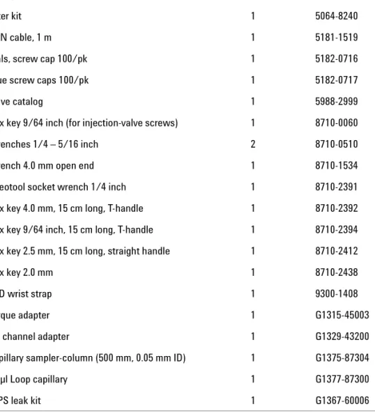
Table 3 Micro well-plate Sampler Accessory Kit Contents G1377-68705
Description Quantity Part Number
96 well-plate 0.5 ml, PP (pack of 10) 1 5042-1386
Tubing assembly 1 5063-6527
Filter kit 1 5064-8240
CAN cable, 1 m 1 5181-1519
Vials, screw cap 100/pk 1 5182-0716
Blue screw caps 100/pk 1 5182-0717
Valve catalog 1 5988-2999
Hex key 9/64 inch (for injection-valve screws) 1 8710-0060
Wrenches 1/4 – 5/16 inch 2 8710-0510
Wrench 4.0 mm open end 1 8710-1534
Rheotool socket wrench 1/4 inch 1 8710-2391 Hex key 4.0 mm, 15 cm long, T-handle 1 8710-2392 Hex key 9/64 inch, 15 cm long, T-handle 1 8710-2394 Hex key 2.5 mm, 15 cm long, straight handle 1 8710-2412
Hex key 2.0 mm 1 8710-2438
ESD wrist strap 1 9300-1408
Torque adapter 1 G1315-45003
Air channel adapter 1 G1329-43200
Capillary sampler-column (500 mm, 0.05 mm ID) 1 G1375-87304
40 µl Loop capillary 1 G1377-87300
20 1100 Series WS MWS Reference Manual
Optimizing the Stack Configuration
If your autosampler is part of a system, you can ensure optimum performance, ensuring minimum delay volume by installing the following configuration.
Figure 1 and Figure 2 on page 21 show the configuration recommended for the sampler. Figure 3 on page 22 and Figure 4 on page 23 show the configuration recommended for the thermostatted sampler.
Figure 1 Recommended Stack Configuration - Well-plate Sampler (Front View) Solvent cabinet Vacuum degasser Pump Column compartment Well-plate sampler Detector Control module
Installing the Sampler
1
1100 Series WS MWS Reference Manual 21
Figure 2 Recommended Stack Configuration - Well-plate Sampler (Rear View) GPIB or LAN to LC ChemStation Analog signal to
recorder Remote cable
CAN Bus cable
AC power
Analog signal to recorder
22 1100 Series WS MWS Reference Manual Figure 3 Recommended Stack Configuration - Thermostatted Sampler (Front View) Autosampler
ALS Thermostat Column Compartment
Detector Control Module
Pump Degasser Solvent Cabinet
Installing the Sampler
1
1100 Series WS MWS Reference Manual 23
Figure 4 Recommended Stack Configuration - Thermostatted Sampler (Rear View) GPIB or LAN to LC ChemStation Analog signal to recorder AC power Remote cable
CAN bus cable
Autosampler -Thermostat cable
AC power Analog signal
24 1100 Series WS MWS Reference Manual
Installing the Sampler
1 Install the LAN interface board in the sampler (if required), see “Interface Board"on page 129.
2 Remove the adhesive tape which covers the side and front doors.
3 Open the front door and remove the left side door.
4 Remove the transport protection foam.
5 Re-install the corrugated waste tube in the plastic port.
6 Re-install the left side door (take care of the magnet at the back).
7 Place the autosampler in the stack or on the bench in all horizontal position.
8 Ensure the power switch at the front of the sampler is OFF.
9 Connect the power cable to the power connector at the rear of the sampler.
10Connect the CAN cable to the other Agilent 1100 modules.
11If a Agilent ChemStation is the controller, connect either • the GPIB cable to the detector
• the LAN connection to the LAN interface
12Connect the APG remote cable (optional) for non Agilent 1100 Series instruments.
13Ensure the side panel is correctly installed.
Preparation Locate bench space Provide power connections Unpack the sampler Parts required Sampler
Power cord, for the other cables see below and “Cable Overview"on page 178 Chemstation and/or Control Module G1323B
WA R N I N G
To avoid personal injury, keep fingers away from the needle area during autosampleroperation. Do not attempt to insert or remove a vial or a plate when the needle is positioned.
Installing the Sampler
1
1100 Series WS MWS Reference Manual 25
14Turn ON power by pushing the button at the lower left hand side of the sampler.
15Close the front door. The exhaust fan will turn ON and remove the vapor from the tray compartment. After 1-2 minutes the sampler will start the hardware initialisation process. At the end of this process the status LED should be green.
Figure 5 Cable Connections Vial number output
CAN cable to next module CAN cable to previous module
Control of Thermostat
N O T E
The sampler is turned ON when the line power switch is pressed and the green indicatorlamp is illuminated. The detector is turned OFF when the line power switch is protruding and the green light is OFF.
WA R N I N G
To disconnect the sampler from the line, unplug the power cord. The power will26 1100 Series WS MWS Reference Manual
Installing a Thermostatted Sampler
1 Place the thermostat on the bench.
2 Remove the front cover and route the condensation drain tube to the waste bottle.
3 Install the LAN interface board in the sampler (if required), see “Interface Board"on page 129.
4 Remove the adhesive tape which covers the side and front doors.
5 Open the front door and remove the left side door.
6 Remove the transport protection foam.
7 Re-install the corrugated waste tube in the plastic port.
Preparation Locate bench space Provide power connections
Unpack the sampler and the thermostat Parts required Sampler and thermostat
Power cord, for the other cables see below and,“Cable Overview"on page 178 ChemStation and/or Control Module G1323B
WA R N I N G
Make sure that the condensation drain tube is always above the liquid level in thevessel. If the tube is located in liquid the condensed water cannot flow out of the tube and the outlet is blocked. Any further condensation will then remain in the instrument. This may damage the instruments electronics.
Figure 6 Condensation leak outlet Condensation drain tube
Installing the Sampler
1
1100 Series WS MWS Reference Manual 27
8 Re-install the left side door (take care of the magnet at the back).
9 Place the sampler on top of the thermostat. Make sure that the sampler is correctly engaged in the thermostat locks.
10Remove the tray and the plastic cover from the tray base, place the air channel adapter into the sampler tray base. Make sure the adapter is fully pressed down. This assures that the cold airstream from the thermostat is correctly guided to the tray area of the well-plate sampler.
11Re-install the tray.
12Ensure the power switch on the front of the sampler is 0FF and the power cables are disconnected.
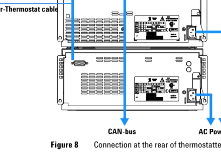
13Connect the cable between the well-plate sampler and the thermostat, see
“Connection at the rear of thermostatted Sampler"on page 29.
Figure 7 Installation of Thermostat and Sampler Air channel adapter
WA R N I N G
Do not disconnect or reconnect the well-plate sampler to thermostat cable when thepower cords are connected to either of the two modules. This will damage the electronics of the modules.
28 1100 Series WS MWS Reference Manual 14Connect the power cables to the power connectors.
15Connect the CAN cable to other Agilent 1100 series modules.
16If a Agilent ChemStation is the controller, connect either • the GPIB cable to the detector
• the LAN connection to the LAN interface
17Connect the APG remote cable (optional) for non Agilent 1100 Series instruments.
18Ensure the side panel is correctly installed.
19Turn ON power by pushing the button at the lower left hand side of the sampler.
20Close the front door. The exhaust fan will turn ON and remove the vapor from the tray compartment. After 1-2 minutes the sampler will start tile hardware initialisation process. At the end of this process the status LED should be green.
N O T E
The sampler is turned ON when the line power switch is pressed and the green indicatorlamp is illuminated. The detector is turned 0FF when the line power switch is protruding and the green light is 0FF.
WA R N I N G
To disconnect the sampler from the line, unplug the power cord. The power supplystill uses some power, even if the power switch at the front panel is turned 0FF.
WA R N I N G
To avoid personal injury, keep fingers away from the needle area during autosampleroperation. Do not attempt to insert or remove a vial or a plate when the needle is positioned.
Installing the Sampler
1
1100 Series WS MWS Reference Manual 29
Figure 8 Connection at the rear of thermostatted Sampler Sampler-Thermostat cable
30 1100 Series WS MWS Reference Manual
Flow Connections to the Sampler
1 Connect the pump outlet capillary to port 1 of the injection valve.
2 Connect column-compartment inlet capillary to port 6 of the injection valve.
3 Connect the corrugated waste tube to the seat adapter and the solvent waste from the leak plane.
4 Ensure that the waste tube is positioned inside the leak channel.
5 Drive the tube from the peristaltic flush pump to the solvent bottle in the solvent cabinet
6 Seat capillary: see recommendations in “Choice of Seat Capillary"on page 54
Preparation Sampler is installed in the LC system
Parts required Parts form the accessory kits, see “Accessory Kits"on page 18
WA R N I N G
When opening capillary or tube fittings, solvents may leak out. Please observeappropriate safety procedures (for example, goggles, safety gloves and protective clothing) as described in the material handling and safety data sheet supplied by the solvent vendor, especially when toxic or hazardous solvents are used.
Installing the Sampler
1
1100 Series WS MWS Reference Manual 31
Figure 9 Hydraulic Connections
from pump to column to waste Corrugated tube Loop capillary waste tube
32 1100 Series WS MWS Reference Manual
Sample Trays
Installing the Well-plate Sample Tray
1 Press the bottom on the right side to release the front door.
2 Lift the front door.
3 Load the sample tray with sample well-plates and vials as required.
4 Slide the sample tray into the autosampler so that the rear of the sample tray is seated firmly against the rear of the sample-tray area.
5 Press the front of the sample tray down to secure the tray in the autosampler.
N O T E
If the tray pops out of position the air channel adapter is not correctly inserted.Installing the Sampler
1
1100 Series WS MWS Reference Manual 33
Supported Trays for a Standard Sampler
Supported Trays for a Thermostatted Sampler
Table 4 Trays for a standard samplersG1367-60001 Tray for 2 plates and 10 x 2 ml vials G1313-44500 Tray for 100 x 2 ml vials
Table 5 Trays for a thermostatted samplers
G1367-60001 Tray for 2 plates and 10 x 2 ml vials G1329-60001 Tray for 100 x 2 ml vials, thermostattable
Figure 11 Numbering of vial and well plate position
Vial 1 Vial 10 Pos. P2-P24 Plate 2 Pos. P2-A1 Pos. P2-B1 Pos. P1-H12 Pos. P1-A1 Pos. P1-B1 Plate 1
34 1100 Series WS MWS Reference Manual
List of recommended Plates and Closing Mat
Table 6 Recommended plates and closing mat
Description Rows Columns Plate height Volume (µI) Part Number Package
384Agilent 16 24 14.4 80 5042-1388 30 384Corning 16 24 14.4 80 No Agilent PN 384Nunc 16 24 14.4 80 No Agilent PN 96Agilent 8 12 14.3 400 5042-1386 5042-1385 10 120 96CappedAgilent 8 12 47.1 300 5065-4402 1 96Corning 8 12 14.3 300 No Agilent PN 96CorningV 8 12 14.3 300 No Agilent PN 96DeepAgilent31mm 8 12 31.5 1000 5042-6454 50 96DeepNunc31mm 8 12 31.5 1000 No Agilent PN 96DeepRitter41mm 8 12 41.2 800 No Agilent PN 96Greiner 8 12 14.3 300 No Agilent PN 96GreinerV 8 12 14.3 250 No Agilent PN 96Nunc 8 12 14.3 400 No Agilent PN
Closing mat for all 96 Agilent plates
8 12 5042-1389 50
WA R N I N G
If you are using flammable solvents, remove the plates from the sampler afterturning it 0FF. You avoid the risk of building explosive gas mixtures in the instrument.
WA R N I N G
If you are using flammable solvents, cover the plates. You avoid the risk of buildingInstalling the Sampler
1
1100 Series WS MWS Reference Manual 35
WA R N I N G
Closing mats with adhesive can give some contamination in the system. Theadhesive is soluble in most of the solvents used in HPLC.
WA R N I N G
In general do not use closing mats with adhesive. The sampler has no prepunch36 1100 Series WS MWS Reference Manual
List of Recommended Vials and Caps
Table 7 Crimp Top Vials
Description Volume (ml) lOO/Pack lOOO/Pack lOO/Pack (silanized) Clear glass 2 5181-3375 5183-4491 Clear glass, write-on spot 2 5182-0543 5183-4492 5183-4494 Amber glass, write-on spot 2 5182-3376 5183-4493 5183-4495
Table 8 SnapTop Vials
Description Volume (ml) lOO/Pack lOOO/Pack lOO/Pack (silanized) Clear glass 2 5182-0544 5183-4504 5183-4507 Clear glass, write-on spot 2 5182-0546 5183-4505 5183-4508 Amber glass, write-on spot 2 5182-0545 5183-4506 5183-4509
Table 9 Screw Top Vials
Description Volume (ml) lOO/Pack lOOO/Pack lOO/Pack (silanized) Clear glass 2 5182-0714 5183-2067 5183-2070 Clear glass, write-on spot 2 5182-0715 5183-2068 5183-2071 Amber glass, write-on spot 2 5182-0716 5183-2069 5183-2072
Installing the Sampler
1
1100 Series WS MWS Reference Manual 37
Table 10 Crimp Caps
Description Septa 100/Pack
Silver aluminum Clear PTFE/red rubber 5181-1210
Silver aluminum Clear PTFE/red rubber 5183-4498 (1000/Pack) Blue aluminum Clear PTFE/red rubber 5181-1215
Green aluminum Clear PTFE/red rubber 5181-1216 Red aluminum Clear PTFE/red rubber 5181-1217
Table 11 Snap Caps
Description Septa 100/Pack
Clear polypropyIene Clear PTFE/red rubber 5182-0550 BIue polypropylene Clear PTFE/red rubber 5182-3458 Green polypropylene Clear PTFE/red rubber 5182-3457 Red polypropylene Clear PTFE/red rubber 5182-3459
Table 12 Screw Caps
Description Septa 100/Pack
BIue polypropyIene Clear PTFE/red rubber 5182-0717 Green polypropyIene Clear PTFE/red rubber 5182-0718 Red polypropylene Clear PTFE/red rubber 5182-0719 BIue polypropylene Clear PTFE/silicone 5182-0720 Green polypropylene Clear PTFE/silicone 5182-0721 Red polypropyIene Clear PTFE/silicone 5182-0722
38 1100 Series WS MWS Reference Manual
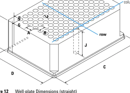
Configure Well-plate Types
If the plate you are using is not found on the “List of recommended Plates and Closing Mat"on page 34 you may configure a custom plate. Measure the exact dimensions of the plate as marked below and enter the values in the plate configuration table of the ChemStation or the Control Module.
Figure 12 Well-plate Dimensions (straight) G B C D E A F I J column row
Installing the Sampler
1
1100 Series WS MWS Reference Manual 39
Figure 13 Well-plate Dimensions (staggered) Table 13 Well Plate Dimensions
Location Description Definition Limits
Rows Number of rows on the plate up to 16 Columns Number of columns on the plate up to 24 Volume Volume (in µI) of a sample vessel
A Row distance Distance (in mm) between the center of two rows
B Column distance Distance (in mm) between the center of two columns
C Plate length X size (in mm) at the bottom of the plate
127.75+/- 0.25 mm (SBS Standard) D Plate width Y size (in mm) at the bottom of the
plate
85.50+/-0.25 mm (SBS Standard) E Plate height Size (in mm) from the bottom to the
top of the plate
up to 47 mm G B C D E A F I J H
40 1100 Series WS MWS Reference Manual F Row offset Distance (in mm) from the back
edge (bottom) to the center of the first hole (A1)
G Column offset Distance (in mm) from the left edge (bottom) to the center of the first hole (A1)
H Column shift Offset (in mm) to Y when the rows are not straight but staggered
l Well diameter Diameter (in mm) of the well at least 4 mm J WeIl depth Distance (in mm) from the top of the
plate to the bottom of the well
up to 45 mm Table 13 Well Plate Dimensions (continued)
Location Description Definition Limits
Installing the Sampler
1
1100 Series WS MWS Reference Manual 41
Transporting the Sampler
When moving the autosampler inside the laboratory, no special precautions are needed. However, if the autosampler needs to be shipped to another location via carrier, ensure:
• The transport assembly is in the park position. Use the ChemStation or the Control Module for this command.
• The vial tray and the sample transport mechanism is secured with the transport protection foam.
43
Agilent 1100 Series Well-plate Sampler & Micro Well-plate Sampler Reference Manual
Agilent Technologies
2
Optimizing Performance
Optimizing Performance 44Optimization for Lowest Carry-over 45 Fast Injection Cycle and Low Delay Volume 49 Precise Injection Volume 51
Choice of Rotor Seal 53 Choice of Seat Capillary 54
44 1100 Series WS MWS Reference Manual
Optimizing Performance
Autosamplers are more and more used in HPLC to improve the productivity in the laboratories and the consistency and accuracy of analytical results. The informations below will help you on how to optimize some parameters to achieve best results for:
• lowest carry-over for reliable quantitative data
• Fast injection cycles for high throughput
• Low delay volume for fast gradient
Optimizing Performance
2
1100 Series WS MWS Reference Manual 45
Optimization for Lowest Carry-over
Several parts of an injection system can contribute to carry-over:
• needle outside • needle inside • needle seat • sample loop • seat capillary • injection valve
The well plate sampler continuous flow-through design ensures that sample loop, needle inside, seat capillary, and the mainpass of the injection valve is always in the flow line. These parts are continuously flushed during an isocratic and also during a gradient analysis. The residual amount of sample remaining on the outside of the needle after injection may contribute to carry-over in some instances. When using small injection volumes or when injecting samples of low concentration immediately after samples of high concentration, carry-over may become noticeable. Cleaning the needle in the flush port or using the automated needle wash enables the carry-over to be minimized and prevents also contamination of the needle seat.
Using the Automated Needle Wash
The automated needle wash can be programmed either as “injection with needle wash” or the needle wash can be included into the injector program. When the automated needle wash is used, the needle is moved into a wash vial after the sample is drawn. By washing the needle after drawing a sample, the sample is removed from the surface of the needle immediately.
Uncapped Wash Vial
For best results, the wash vial should contain solvent in which the sample components are soluble, and the vial should not be capped. If the wash vial is capped, small amounts of sample remain on the surface of the septum, which may be carried on the needle to the next sample.
46 1100 Series WS MWS Reference Manual
Injector Program with Needle Wash
The injector program includes the command NEEDLE WASH. When this command is included in the injector program, the needle is lowered once into the specified wash vial before injection.
For example: 1 DRAW 5 µl
2 NEEDLE WASH vial 7 3 INJECT
Line 1 draws 5 µl from the current sample vial. Line 2 moves the needle to vial 7. Line 3 injects the sample (valve switches to main pass).
Using the Flush Port
During the injection process when the sample is in the loop and when the valve still is in Bypass, the outside of the needle can be washed in a flush port located behind the injection port on the sampling unit. As soon the needle is in the flush port a peristaltic pump fills the flush port with fresh solvent during a defined time. The volume of the flush port is about 680 µl and the pump delivers 6 ml/min. Setting the wash time to 10 seconds is sufficient to refill 2 times the flush port. In most cases this is enough to clean the needle outside. At the end of this flush process the needle return to the injection port, the valve is switched to the Mainpass position and directs the pump flow back through the sample loop.
Further reduction of carry-over can be obtained using an injector program with additional injection valve switching, see “Using an Injector Program"on page 47
Recommended wash solvents
• water
• ethanol
• methanol
• water/acid
Optimizing Performance
2
1100 Series WS MWS Reference Manual 47
Using an Injector Program
The process is based on a program that switches the bypass grove of the injection valve into the flow line for cleaning. This switching event is
performed at the end of the equilibration time to ensure that the bypass grove is filled with the start concentration of the mobile phase. Otherwise the separation could be influenced, especially if microbore columns are used.
For example:
Outside wash of needle before injection: 14 sec. using flush port Injector program:
Draw x.x (y) µl from sample Needle wash as method Inject
Wait (equilibration time - see text above) Valve bypass
Wait 0.2 min Valve mainpass Valve bypass Valve mainpass
Using such an injector program in addition with the needle wash in the flush port can reduce the carry-over by a factor of about 10 compared with a standard needle wash in the flush port only.
N O T E
The live time of the tubing in the peristaltic pump is shorted by the usage of organicsolvents.
48 1100 Series WS MWS Reference Manual
General Recommendation to Lowest Carry-over
• Prime flush pump daily for 3 minutes with appropriate solvent previous to the first run.
• Set needle wash in flush port to at least 10 seconds.
• Use previously described injector program (page 47) as injection mode if carry-over is significantly higher than 0.01 %.
• For samples where needle outside cannot be cleaned sufficiently with water or alcohol use wash vials with an appropriate solvent. Using an injector program and several wash vials can be used for cleaning.
In case the needle seat has got contaminated and carry-over is significantly higher than expected, the following procedure can be used to clean the needle seat:
• Go to MORE INJECTOR and set needle to home position.
• Pipette an appropriate solvent on to the needle seat. The solvent should be able to dissolve the contamination. If this is not known use 2 or 3 solvents of different polarity. Use several milliliters to clean the seat. The liquid leaves the seat via the drainage for the flush port.
• Clean the needle seat with a tissue and remove all liquid from it.
Optimizing Performance
2
1100 Series WS MWS Reference Manual 49
Fast Injection Cycle and Low Delay Volume
Short injection cycle times for high sample througput is one of the main issues in analytical laboratories. Shortening cycle time starts with:
• shortening column length
• high flow rate
• steep gradient
Having optimized these parameters, further reduction of cycle times can be obtained using the overlapped injection mode.
Overlapped Injection Mode
In this process, as soon as the sample has reached the column, the injection valve is switched back to bypass and the next injection cycle starts but waits with switching to mainpass until the actual run is finished. You gain the sample preparation time when using this process.
Switching the valve into the bypass position reduces the system delay volume by approximately 300 µl (the mobile phase is directed to the column without passing sample loop, needle and needle seat capillary). This can help to have faster cycle times especially if low flow rates have to be used like it is
mandatory in narrow bore and micro bore HPLC.
50 1100 Series WS MWS Reference Manual
The injection cycle times also depend on the injection volume. In identically standard condition, injecting 100 µl instead of 1 µl, increase the injection time by approximately 8 sec. In this case and if the viscosity of the sample allows it, the draw and eject speed of the injection system has to be increased.
General Recommendations for Fast Injection Cycle Times
As described in this section, the first step to provide short cycle times are optimizing the chromatographic conditions. If this is done the well-plate sampler parameter should be set to:
• Overlapped injection mode
• Wash time for needle outside set to 10 seconds
• Increase of draw and eject speed for large injection volumes
• Add at last run a blank, if overlapped injection is used
To reduce the injection time, the detector balance has to be set to OFF.
N O T E
For the last injection of the sequence with overlapped injections it has to be consideredthat for this run the injection valve is not switched as for the previous runs and
consequently the injector delay volume is not bypassed. This means the retention times are prolonged for the last run. Especially at low flow rates this can lead to retention time changes which are to big for the actual calibration table. To overcome this it is recommended to add an additional “blank” injection as last injection to the sequence.
Optimizing Performance
2
1100 Series WS MWS Reference Manual 51
Precise Injection Volume
Injection Volumes Less Than 2 µl
When the injection valve switches to the BYPASS position, the mobile phase in the sample loop is depressurized. When the syringe begins drawing sample, the mobile phase is further subjected to decreasing pressure. If the mobile phase is not adequately degassed, small gas bubbles may form in the sample loop during the injection sequence. When using injection volumes < 2 µl, these gas bubbles may affect the injection-volume precision. For best
injection-volume precision with injection volumes < 2 µl, use of the
Agilent 1100 Series degasser is recommended to ensure the mobile phase is adequately degassed. Also, using the automated needle wash (see
“Optimization for Lowest Carry-over"on page 45) between injections reduces carry-over to a minimum, improving injection-volume precision further.
Draw and Eject Speed
Draw Speed
The speed at which the metering unit draws sample out of the vial may have an influence on the injection volume precision when using viscous samples. If the draw speed is too high, air bubbles may form in the sample plug, affecting precision. The default draw speed is suitable for the majority of applications, however, when using viscous samples, set the draw speed to lower speed for optimum results. A “DRAW” statement in an injector program also uses the draw speed setting which is configured for the well plate sampler.
Eject Speed
The default draw speed is suitable for the majority of applications. When using large injection volumes, setting the eject speed to a higher value speeds up the injection cycle by shortening the time the metering unit requires to eject solvent at the beginning of the injection cycle (when the plunger returns to the home position).
An “EJECT” statement in an injector program also uses the eject speed setting which is configured for the well plate sampler. A faster eject speed shortens the time required to run the injector program. When using viscous samples, a high eject speed should be avoided.
52 1100 Series WS MWS Reference Manual Table 14 Draw and eject speed
Draw speed (µl) Eject speed (µl) Well Plate Sampler
Default value 200 200
Minimum 10 10
Maximum 1000 1000
Micro Well Plate Sampler with 8µl loop capillary
Default value 4 10
Minimum 0.7 0.7
Maximum 20 100
Micro Well Plate Sampler with 40µl loop capillary
Default value 4 10
Minimum 0.7 0.7
Optimizing Performance
2
1100 Series WS MWS Reference Manual 53
Choice of Rotor Seal
Vespel
™
Seal
The standard seal has sealing material made of Vespel. Vespel is suitable for applications using mobile phases within the pH range of 2.3 to 9.5, which is suitable for the majority of applications. However, for applications using mobile phases with pH below 2.3 or above 9.5, the Vespel seal may degrade faster, leading to reduced seal lifetime.
Tefzel
™
Seal
For mobile phases with pH below 2.3 or above 9.5, or for conditions where the lifetime of the Vespel seal is drastically reduced, a seal made of Tefzel is available (see “Injection-Valve Assembly"on page 167). Tefzel is more resistant than Vespel to extremes of pH, however, is a slightly softer material. Under normal conditions, the expected lifetime of the Tefzel seal is shorter than the Vespel seal, however, Tefzel may have the longer lifetime under more extreme mobile phase conditions.
54 1100 Series WS MWS Reference Manual
Choice of Seat Capillary
Different models of seat capillaries are available for the well-plate sampler and the micro well-plate sampler:
For the Well-plate Sampler
The needle seat assembly includes the needle seat and the seat capillary. The part number for this assembly is: G1367-87101.
For the Micro Well-plate Sampler
The needle seat assembly is made up of two parts:
• needle seat: G1377-87101.
• seat capillary
choice of: G1375-87317 (100 µm 150 mm) G1375-87300 (50 µm 150 mm)
G1375-87317 (100 µm) is the capillary preinstalled in micro well-plate and thermostatted micro well-plate samplers upon delivery.
This capillary is recommended for applications with a 0.3 mm column or higher. It provides less plugging of the capillary in general and especially with biological samples. For small K’ this capillary can provide a higher peak width for isocratic analysis.
G1375-87300 (50 µm) is available as a spare part and is recommended for applications with a 0.3 mm column or smaller. This capillary gives full chromatographic performance.
55
Agilent 1100 Series Well-plate Sampler & Micro Well-plate Sampler Reference Manual
Agilent Technologies
3
Troubleshooting and Test Functions
Overview of the Sampler’s Indicators and Test Functions 56 Status Indicators 58Error Messages 60 Maintenance Functions 88 Step Commands 90
Troubleshooting Guide for the Well Plate Sampler G1367A 93 Turn ON and initialization steps 94
Instrument logbook errors and step by step repair process 99 Needle centering over the vial or the well 104
56 1100 Series WS MWS Reference Manual
Overview of the Sampler’s Indicators and Test Functions
Status Indicators
The sampler is provided with two status indicators which indicate the operational state (prerun, not ready, run, and error states) of the instrument. The status indicators provide a quick visual check of the operation of the sampler (see “Status Indicators"on page 58).
Error Messages
In the event of an electronic, mechanical or hydraulic failure, the instrument generates an error message in the user interface. For each message, a short description of the failure, a list of probable causes of the problem, and a list of suggested actions to fix the problem are provided (see “Error Messages"on page 60).
Maintenance Functions
The maintenance functions position the needle assembly, the needle carrier, the sample transport assembly and the metering device for easy access when doing maintenance (see “Maintenance Functions"on page 88).
Sample Transport Self Alignment
The sample transport self alignment with the sampling unit and the well-plate tray is required to compensate for larger deviations in positioning the needle carrier.
The sample transport self alignment is required after disassembling the system or when you exchange the sample transport, the sampling unit, the tray or the MTP main board.
This function is in the diagnose screen of the Chemstation or the Control Module.
WA R N I N G
The sample transport self alignment requires the standard well-plate tray (PartTroubleshooting and Test Functions
3
1100 Series WS MWS Reference Manual 57
Step Commands
The step functions enable execution of each step of the sampling sequence individually. The step functions are used primarily for troubleshooting, and for verification of correct sampler operation after repair (see “Step
Commands"on page 57).
58 1100 Series WS MWS Reference Manual
Status Indicators
Two status indicators are located on the front of the sampler. The lower left indicates the power supply status, the upper right indicates the sampler status.
Power Supply Indicator
The power supply indicator is integrated into the main power switch. When the indicator is illuminated (green) the power is ON.
Figure 14 Location of Status Indicators Status indicator
green/yellow/red
Line power switch with green light
Troubleshooting and Test Functions
3
1100 Series WS MWS Reference Manual 59
Instrument Status Indicator
The instrument status indicator indicates one of four possible instrument conditions:
• When the status indicator is OFF (and power switch light is on), the instrument is in a prerun condition, and is ready to begin an analysis.
• A green status indicator indicates the instrument is performing an analysis (run mode).
• A yellow status indicator indicates a not-ready condition. The instrument is in a not-ready state when it is waiting for a specific condition to be reached or completed (for example, front door not closed), or while a self-test procedure is running.
• An error condition is indicated when the status indicator is red. An error condition indicates the instrument has detected an internal problem which affects correct operation of the instrument. Usually, an error condition requires attention (for example, leak, defective internal components). An error condition always interrupts the analysis.
60 1100 Series WS MWS Reference Manual
Error Messages
Error messages are displayed in the user interface when an electronic, mechanical, or hydraulic (flow path) failure occurs which requires attention before the analysis can be continued (for example, repair, exchange of consumables is necessary). In the event of such a failure, the red status indicator at the front of the module is switched on, and an entry is written into the instrument log book.
This section explains the sampler error messages, and provides information on probable causes and suggested actions to recover from error conditions.
Troubleshooting and Test Functions
3
1100 Series WS MWS Reference Manual 61
Timeout
The timeout threshold was exceeded.
Probable Causes
• The analysis was completed successfully, and the timeout function switched off the pump as requested.
• A not-ready condition was present during a sequence or multiple-injection run for a period longer than the timeout threshold.
Suggested Actions
✔ Check the logbook for the occurrence and source of a not-ready condition. Restart the analysis where required.
62 1100 Series WS MWS Reference Manual
Shutdown
An external instrument has generated a shut-down signal on the remote line. The sampler continually monitors the remote input connectors for status signals. A LOW signal input on pin 4 of the remote connector generates the error message.
Probable Causes
• Leak detected in another Agilent 1100 module with a CAN connection to the system.
• Error detected in an external instrument with a remote connection to the system.
• The degasser failed to generate sufficient vacuum for solvent degassing.
Suggested Actions
✔ Determine which Agilent 1100 module has the leak. Fix the leak before restarting the well-plate sampler.
✔ Check external instruments for an error condition.
✔ Check the degasser for an error condition. Refer to the Reference Manual
Troubleshooting and Test Functions
3
1100 Series WS MWS Reference Manual 63
Remote Timeout
A not-ready condition is still present on the remote input.
When an analysis is started, the system expects all not-ready conditions (e.g. a not-ready condition during detector balance) to switch to run conditions within one minute of starting the analysis. If a not-ready condition is still present on the remote line after one minute the error message is generated.
Probable Causes
• Not-ready condition in one of the instruments connected to the remote line.
• Defective remote cable.
• Defective components in the instrument showing the not-ready condition.
Suggested Actions
✔ Ensure the instrument showing the not-ready condition is installed correctly, and is set up correctly for analysis.
✔ Exchange the remote cable.
✔ Check the instrument for defects (refer to the instrument’s reference documentation).
64 1100 Series WS MWS Reference Manual
Synchronization Lost
During an analysis, the internal synchronization or communication between one or more of the modules in the system has failed.
The system processors continually monitor the system configuration. If one or more of the modules is no longer recognized as being connected to the system, the error message is generated.
Probable Causes
• CAN cable disconnected.
• Defective CAN cable.
• Defective main board in another module.
Suggested Actions
✔ Ensure all the CAN cables are connected correctly.
✔ Switch off the system. Restart the system, and determine which module or modules are not recognized by the system.
Troubleshooting and Test Functions
3
1100 Series WS MWS Reference Manual 65
Leak
A leak was detected in the sampler.
The signals from the two temperature sensors (leak sensor and
board-mounted temperature-compensation sensor) are used by the leak algorithm to determine whether a leak is present. When a leak occurs, the leak sensor is cooled by the solvent. This changes the resistance of the leak sensor which is sensed by the leak-sensor circuit on the MTP board.
Probable Causes
• Loose fittings.• Broken capillary.
• Leaking rotor seal or needle seat.
• Defective metering seal.
Suggested Actions
✔ Ensure all fittings are tight.
✔ Exchange defective capillaries.
✔ Exchange the rotor seal or seat capillary.
✔ Exchange the metering seal.
N O T E
Make sure the leak sensor is thoroughly dry before restarting the well-plate sampler.N O T E
Crossflow caused by a leaky rotor seal may cause a spill over of seat in bypass position of66 1100 Series WS MWS Reference Manual
Leak Sensor Open
The leak sensor in the sampler has failed (open circuit).
The current through the leak sensor is dependent on temperature. A leak is detected when solvent cools the leak sensor, causing the leak-sensor current to change within defined limits. If the current falls outside the lower limit, the error message is generated.
Probable Causes
• Leak sensor not connected to the MTP board.
• Defective leak sensor.
Suggested Actions
✔ Ensure the leak sensor is connected correctly.
Troubleshooting and Test Functions
3
1100 Series WS MWS Reference Manual 67
Leak Sensor Short
The leak sensor in the sampler has failed (short circuit).
The current through the leak sensor is dependent on temperature. A leak is detected when solvent cools the leak sensor, causing the leak-sensor current to change within defined limits. If the current increases above the upper limit, the error message is generated.
Probable Causes
• Defective leak sensor.
Suggested Actions
68 1100 Series WS MWS Reference Manual
Compensation Sensor Open
The ambient-compensation sensor (NTC) on the MTP board in the sampler has failed (open circuit).
The resistance across the temperature compensation sensor (NTC) on the MTP board is dependent on ambient temperature. The change in resistance is used by the leak circuit to compensate for ambient temperature changes. If the resistance across the sensor increases above the upper limit, the error message is generated.
Probable Causes
• Defective MTP board.
Suggested Actions
Troubleshooting and Test Functions
3
1100 Series WS MWS Reference Manual 69
Compensation Sensor Short
The ambient-compensation sensor (NTC) on the MTP board in the sampler has failed (short circuit).
The resistance across the temperature compensation sensor (NTC) on the MTP board is dependent on ambient temperature. The change in resistance is used by the leak circuit to compensate for ambient temperature changes. If the resistance across the sensor falls below the lower limit, the error message is generated.
Probable Causes
• Defective MTP board.
Suggested Actions
70 1100 Series WS MWS Reference Manual
Fan Failed
The cooling fan in the sampler has failed.
The hall sensor on the fan shaft is used by the MTP board to monitor the fan speed. If the fan speed falls below 2 revolutions/second for longer than 5 seconds, the error message is generated.
Probable Causes
• Fan cable disconnected.
• Defective fan.
• Defective MTP board.
Suggested Actions
✔ Ensure the fan is connected correctly.
✔ Exchange fan.
Troubleshooting and Test Functions
3
1100 Series WS MWS Reference Manual 71
Exhaust Fan Failed
The exhaust fan in the well-plate sampler has failed.
The hall sensor on the fan shaft is used by the WPS board to monitor the fan speed. If the fan speed falls below a certain value the error message is generated and the well-plate sampler shuts down.
Probable Causes
• Fan cable disconnected.
• Defective fan.
• Defective MTP board.
Suggested Actions
✔ Ensure the fan is connected correctly.
✔ Exchange fan.
72 1100 Series WS MWS Reference Manual
Front Door Error
The front door and/or the SLS board are damaged.
Probable Causes
• The sensor on the SLS board is defective.
• The door is bent or the magnet is misplaced/broken.
Suggested Actions
✔ Exchange the door.
✔ Exchange the SLS board.
Troubleshooting and Test Functions
3
1100 Series WS MWS Reference Manual 73
Side Door Error
The side door and/or the MTP board are damaged.
Probable Causes
• The door is bent or the magnet is misplaced/broken.
• The sensor on the MTP board is defective.
Suggested Actions
✔ Change the side door.
74 1100 Series WS MWS Reference Manual
Arm Movement Failed or Arm Movement Timeout
The transport assembly was unable to complete a movement in one of the axes.
The processor defines a certain time window for the successful completion of a movement in any particular axis. The movement and position of the
transport assembly is monitored by the encoders on the stepper motors. If the processor does not receive the correct position information from the encoders within the time window, the error message is generated.
See figure for axes identification.
Arm Movement 0 Failed: X-axis.
Arm Movement 1 Failed: Z-axis.
Arm Movement 2 Failed: Theta (needle car