Lafarge
CONTENTS
Lafarge
Partitioning Solutions
01 LAFARGE PLASTERBOARD
02 LAFARGE FIXED PARTITION
03 LAFARGE FINESSE DEMOUNTABLE PARTITION
04 LAFARGE TOILET PARTITION
4
LAFARGE PLASTERBOARD
Lafarge
Plasterboard.
Lafarge Plasterboard consists of an aerated gypsum core
encased in and firmly bonded on both sides with special
plasterboard liner, rendering a smooth yet highly functional
surface. Special characteristics of gypsum provide the
outstanding advantages over other flat sheet materials. The
board is fabricated by a modern automatic process with the
supervision of highly experienced engineers and chemists.
The question of quality versus speed has always been a
contentious one in interior design. Economics and demand
require buildings to go up quickly and affordably, which could
compromise quality.
Lafarge Plasterboard: Designed for internal walls, ceilings
and partitions in residential and commercial buildings, is
quick and easy to install, while still being durable, recyclable,
aesthetic and of superior quality without the necessary drying
time for alternate wet trade solutions.
Want to know what separates a great interior from the
average?
There are three types of Lafarge Plasterboard
available from Lafarge Gypsum:
Lafarge Standard Plasterboards are exceptionally versatile
and lightweight. They can be used for domestic and
commercial ceiling applications as well as walling/
partitioning applications. Lafarge Plasterboard is also used
to make prefabricated bulkheads, curved ceilings (barrel)
and radiused walls among other innovative applications.
Lafarge Plasterboard is a durable, versatile product that is
clean and recyclable.
When combined with our Lafarge Ceiling Grid suspension
system or our Steel Brandering, an extremely flat ceiling
surface is achieved.
Lafarge Extra Fire Resistant Plasterboard is recommended
for drywalling in kitchens and areas where additional fire
resistance is required.
All of our Lafarge Plasterboards are tested at SABS Pretoria
Fire Testing facility to SANS 10177 part 2 - 1981. Walls
can be designed to suite your fire rating requirements up to
a 2 hour fire rating.
To achieve a 30 minute fire rating:
Use 1 sheet of Lafarge 12mmm Plasterboard on both sides
of a Lafarge Ridgeback stud.
To achieve a 1 hour fire rating:
Use 2 sheets of Lafarge 12mm Extra Fire resistant
Plasterboard on both sides of a Lafarge Ridgeback stud.
Use one sheet of Lafarge 15mm Extra Fire Resistant
Plasterboard on either side of a Lafarge Ridgeback stud.
(Refer to Specifications on pg 21)
If longer fire resistance is required, Lafarge Gypsum’s
Technical department is happy to help you specify a
solution for up to 2 hours fire resistance.
Lafarge Moisture Resistant Plasterboard is recommended
for use in all wet areas such as bathroom showers, as well
as locations with high humidity levels. Lafarge Moisture
Resistant Plasterboard is supported with special additives
in the core, to retard the absorption rate of moisture,
ensuring that the Lafarge Plasterboard maintains its high
performance level over time.
LAFARGE PLASTERBOARD
LAFARGE PLASTERBOARD PRODUCT RANGE
Our boards have two different edges:
1.
Square Edge (S.E.) for coverstrip jointing; visible
butt jointed paneling with clamp fixing and fee
suspension.
2.
Tapered Edge (T.E.) for smooth and seamless
jointing; jointless wall and ceiling paneling.
900; 2400; 2700; 3000; 3300; 3600
Length (mm)
Weight kg/m
2 (Approx)Use
Thickness (mm)
Width
Width
1200 5.50 Ceilings Ceilings Partitions Partitions Partitions 9.50 9 6.4 12 1195 2400; 2700; 3000Lafarge Plasterboard Dimensions
S/E can be manufactured to order with minimum quantities
2400; 2700; 3000; 3600 1200 9 12 15 14.0 9.50 7.30 1200 1200 2400; 2700; 3000; 3600 2400; 2700; 3000; 3300; 3600
Weight kg/m
2 (Approx)Use
Length (mm)
Thickness (mm)
Tapered
Edge
Square
Edge
6
LAFARGE PLASTERBOARD
CHARACTERISTIC OF LAFARGE PLASTERBOARD
Lafarge goes to great lengths to ensure that the end user
receives quality products. Testing at the South African
Bureau of Standards is an ongoing process and every
effort is made to ensure testing is as close to site
conditions as possible.
Some of the most important tests are as follows:
• Fire resistant SANS 10177 part 2 – 1981
Here a wall measuring 2.7 by 2.7m is placed in the opening
of a furnace, and fired up to simulate actual fire conditions.
The wall is subjected to this fire and heat for a limited
duration of time as per our request - i.e. 30 minutes / 60
minutes or 120 minutes, depending on the system being
tested.
The Lafarge wall must be able to withstand 3 important
criteria, namely Fire Stability (load bearing capacity), Fire
Integrity (tightness against flame, gas and other leakages)
and Fire Insulation (180 degrees above ambient is the
cutoff limit), before a fire rating can be issue to the system.
Other Tests:
•
Gridlock deflection - SANS 7228/158EMTO1
•
Sag Test BS 8290
•
Sag Test TDC MO3-TDC-022D
•
SANS/ASTM 367-89
•
7228/013/MT01/REVA
•
5544/158C/MT01
•
7228/158C/MT01
•
7228/112A/MT01
•
Pull Test Lafarge Gypsum - TDC M02-TDC-023-D
Storage and Handling of Lafarge Plasterboard
1.
Lafarge Plasterboard should be stacked flat in a dry
and smooth area to avoid ground dampness.
2.
Use wooden bearers as supports.
3.
6,4mm board
= 50 / stack
9mm board
= 60 / stack
12mm
= 2,7m = 60
=
3,3m
=
50
=
3,6m
=
40
12,5mm board (FC + MR)
= 40
15mm
board
=
30
4.
No more than 5 stacks should be piled over one
another. The bearers of each stack must be aligned.
5.
The Lafarge Plasterboards should be kept indoors.
If outside storage is temporarily required, cover the
Lafarge Plasterboards with plastic or waterproof
canvas.
6.
Lafarge Plasterboard should be carried on its edges
in an upright position by two people, rather than
flat. 1 to 2 Lafarge Plasterboards can be carried at
a time.
LAFARGE PLASTERBOARD
LAFARGE PLASTERBOARD PARTITIONS
Partition Installation Using a Lafarge Ridgeback Steel Stud
and Track
1.
Install the galvanised steel stud by laying floor
tracks horizontally on floor and ceiling and
fix in place.
2.
Insert studs vertically in tracks and leave space
between each stud at 400 or 600mm intervals.
The studs are held in place by friction.
3.
Attach 12mm tapered-edge Lafarge Plasterboard
steel studs by driving the 25mm
Drywall screw into it. The space between each
screw should not exceed 220mm.
4.
Conceal the joint corner and screw dimple with
Lafarge Jointing Plaster. Allow for setting
time, then smooth.
Application Details:
•
Set 63.5mm studs spaced at 600mm intervals into
65mm track at floor and ceiling.
•
Apply a base layer of 12.5mm Lafarge Extra Fire
Resistant Plasterboard vertically to each side using
25mm Drywall Screws spaced at 220mm intervals.
•
Fix a layer of 0.5mm galvanised steel sheeting
using 25mm drywall screws.
•
Apply the face layer of 12.5mm Lafarge Extra Fire
Resistant Plasterboard vertically to each side using
41mm Drywall Screws spaced at 220mm intervals.
•
Use Fibatape and Lafarge Jointing Plaster over the
joints.
•
All joints are to be staggered
•
Acoustic enhancement requires sealing between
track, floor, ceiling and any other abutment joints.
Installation of Lafarge Firecheck Plasterboard
For use in office partitioning, residential internal walling, shopping centres, hotels, hospitals, schools or wherever a 2 hour
fire rating or a safe/secure wall is required.
0.5mm Galvanised Steel Sheet 63.5mm Stud 12.0mm Lafarge Firecheck Plasterboard 12.5mm Lafarge Firecheck Plasterboard 65mm Track Acoustic Sealant/Gasket
8
LAFARGE PLASTERBOARD
LAFARGE PLASTERBOARD INSTALLATION TIPS
Partition:
1.
The length of screw for fixing Lafarge Plasterboard
to metal stud is equal to the thickness of Lafarge
Plasterboard plus 10mm.
2.
If the length of the partition is more than 15m, at
every 15m interval an expansion joint must be used
in order to prevent cracking.
3.
Always leave about 10mm space from the floor to
prevent dampness from creeping up the
Plasterboard.
4.
In high humidity areas, use the Lafarge Moisture
Check Plasterboard.
Lafarge Plasterboard can be curved into many forms to fit
various desired interior wall and ceiling designs.
Framing Installation:
The horizontal steel track can be prepared in 2 ways, using
either the internal or external arc web cuts.
1.
Cut one leg and web of top and bottom steel stud
at 50mm intervals for the length of the arc. Leave
about 400mm of uncut steel studs at end of arc.
2.
Bend tracks either as A or B to form curve of
desired radius (90mm max arc).
3.
Attach the steel track to structural elements at floor
and ceiling. Position vertical studs, with open side
facing the same direction and engaging floor and
steel studs.
CURVED SURFACE INSTALLATION OF PARTITIONS
Lafarge Plasterboard Spacing between vertical stud depends on the radius of curve
LAFARGE PLASTERBOARD
DRYWALL SCREW HEAD CONCEALING
A corner bead is used for reinforcing the corner of a Lafarge
Plasterboard partition.
1.
Cut the corner bead to the same length as the
partition height.
2.
Attach it to both sides of the corner.
3.
Fixing 25mm Drywall Screws along the corner
bead at every 100mm interval on both sides.
4.
Conceal both sides of the corner bead with Lafarge
Jointing Plaster approximately 3mm thick. Leave for
70 minutes to set.
5.
Apply the second coating about 300mm wide from
the corner edge.
6.
Allow 24 hours after second coating, smooth with
80 grit sandpaper.
EXTERNAL CORNER CONCEALING FOR PARTITIONS
Apply sufficient Lafarge Jointing Plaster over the screw head to achieve a smooth surface. Allow 30 minutes for the plaster
to set. Apply the second (if required) coat and leave it for 2 hours. Smooth with sand paper.
Lafarge Lafarge Metal Stud Optical Insulation Lafarge Plasterboard 25mm Screw Corner Bead Lafarge Jointing Plaster Lafarge Plasterboard (Ceiling) Lafarge Plasterboard (Partition) Lafarge Plasterboard
10
LAFARGE PLASTERBOARD
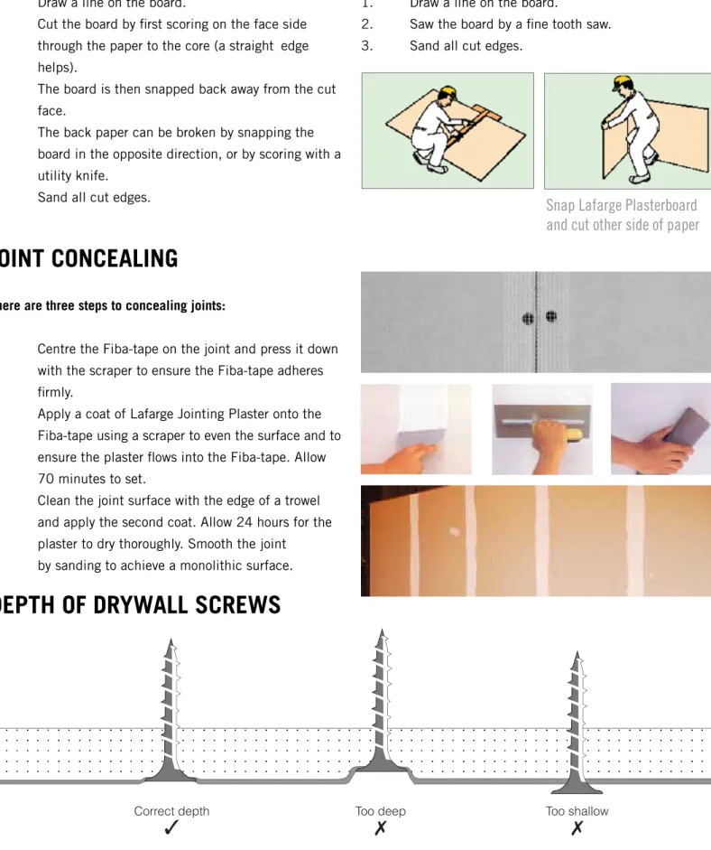
CUTTING LAFARGE PLASTERBOARD
Using a Sharp Cutter
1.
Draw a line on the board.
2.
Cut the board by first scoring on the face side
through the paper to the core (a straight edge
helps).
3.
The board is then snapped back away from the cut
face.
4.
The back paper can be broken by snapping the
board in the opposite direction, or by scoring with a
utility knife.
5.
Sand all cut edges.
JOINT CONCEALING
There are three steps to concealing joints:
1.
Centre the Fiba-tape on the joint and press it down
with the scraper to ensure the Fiba-tape adheres
firmly.
2.
Apply a coat of Lafarge Jointing Plaster onto the
Fiba-tape using a scraper to even the surface and to
ensure the plaster flows into the Fiba-tape. Allow
70 minutes to set.
3.
Clean the joint surface with the edge of a trowel
and apply the second coat. Allow 24 hours for the
plaster to dry thoroughly. Smooth the joint
by sanding to achieve a monolithic surface.
DEPTH OF DRYWALL SCREWS
Using a saw
1.
Draw a line on the board.
2.
Saw the board by a fine tooth saw.
3.
Sand all cut edges.
Lafarge Plasterboard has a unique snap-effect which allows for easy cutting of the board and can be cut by using two
methods.
Diagram Illustrating Screw Depth
Snap Lafarge Plasterboard
and cut other side of paper
Lafarge Drywall is a lightweight non-demountable partition
system which has no visible joints on completion. The
internal framework consists of standard Ridgeback Stud
and Drywall Track profiles manufactured from galvanised
steel. Tapered edge plasterboards are screw fixed to the
studs allowing for plaster jointing. Paint or wallpaper
finishes can then be applied for a joint free wall of
subtle quality.
Attractive Slimline Glazing Mullions and transoms can
be created by clip fixing the required aluminium male
section onto its four legged female partner which has
already been fixed into position.
Door Frame Kits are supplied premitred and with
optional lock cutouts. Full height Door Frames clip
directly onto the Aluminium Female ceiling trim by
means of the Male Aluminium Door header. Standard
door frame kits have both styles and header
manufac-tured from four legged Female Aluminium Door Frame
sections. It is recommended that for additional stability
when erecting full height doors the Ridgeback Stud
should be boxed onto the open side of a Floor Track
prior to fixing (the Female Door Frame Section). Refer
to Fig 6 Pg 7.
The four legged Female partition solutions Aluminium
Door Frame, Glazing and Termination Sections are
positively fixed to the galvanised steel Ridgeback
Studs by means of pop rivets or screws. This ensures
sturdy framing for the Plasterboards and strong
support for the clip-on Male Aluminium sections.
The Aluminium Glazing Bead which carries a neat
Bubble Seal Gasket (or optional woolpile) easily clips
into place after the glass has been positioned, leaving
an attractive Aluminium shopfront type finish, having
slim and clean lines. The Bubble Seal Gasket will
accommodate glass thickness from 4 mm to 6 mm.
(nominal thickness).
Fire rating:
Lafarge Drywall (89 mm
partition) has a 30 minute fire rating as per SABS
0177: Parts-1981. For further details as well as
information on 60 minutes plus fire ratings please
consult with our technical staff.
All Lafarge Aluminium sections may be
Powder Coated or Anodised to complement the
decorated finish of the boards. Aluminium Skirting
or recessed base can be similarly treated to match or
contrast as required.
Lafarge
Fixed
Partition.
12
LAFARGE FIXED PARTITION
Connecting Lafarge Partition Solutions
Lafarge Aluminium Framing
The Lafarge Drywall System consists of Male and Female Aluminium extrusions.
• Female Sections support and position the Lafarge Plasterboard as in conventional drywalling.
• Male Sections are clip fixed to the Female Sections to form Glazing Mullions and Transoms, Doorframe to
Glazing details and to facilitate full height Glazing and full height doors. Bubble Seal Gasket (which is used for both Door frame and Glazing Sections) is to be inserted before constructing the frames.
COMPONENTS
LAFARGE FIXED PARTITION
ALTERNATIVE ALUMINIUM
14
LAFARGE FIXED PARTITION
DOUBLE GLAZING/INTEGRAL BLINDS
1. Aluminium Male ternination Section Die 6161
2. Aluminium 4 leg Female Double Glazing section Die 6201 3. Aluminium Male Door Frame Section Die 6164
4. Aluminium Male Glazing Section Die 6672 5. Aluminium Glazing Bead Die 6674 6. Ridgeback Stud (64mm)
7. 4-6mm Glass 8. Lafarge Plasterboard 9. Bubble Seal Gasket 10. Blinds
11. Blinds mechanism Showing Cable 12. 40mm Door
13. Aluminium Sinkless Hinge 14. Pop Rivets
LAFARGE FIXED PARTITION
ALTERNATIVE ALUMINIUM
16
LAFARGE FIXED PARTITION
CONSTRUCTION DETAILS
1 Lafarge Ridgeback Stud
2 Lafarge Plasterboard (tapered edge) 3 Drywall Screws
4 Skimmed joint
1 Aluminium 4 Leg Female Termination Die 6060/6160 2 Lafarge Plasterboard
3 Drywall Screws
4 Aluminium Termination (alternative) Ceiling and Wall Channel Die 6204/6205
5 Drywall Track
6 Fixing (mechanical/velcro/ grip clip)
1 Aluminium Ribbed Skirting Die 6144 2 Lafarge Plasterboard
3 Lafarge Ridgeback Stud 4 Drywall Track
5 Skirting Screws
1 Aluminium Recessed Head Die 6165/6166 2 Lafarge Ridgeback Stud
3 Lafarge Plasterboard 4 Ceiling Tile
5 Fixing (mechanical/ velcro / grip clip) 6 Drywall Screws
1 Aluminium 4 Leg Female Glazing Die 6668/6679 2 Aluminium Glazing Bead
3 Lafarge Ridgeback Stud 4 Lafarge Plasterboard 5 4-6mm Glass 6 Drywall Screws 7 Bubble Seal Gasket
1 Aluminium 4 Leg Female Glazing Die 6059/6159 2 Lafarge Ridgeback Stud Die 6674
3 Lafarge Plasterboard 4 Door (40mm) 5 Drywall Screws 6 Bubble Seal Gasket
7 Drywall Track (optional for additional stability for full height/solid doors and swing doors).
LAFARGE FIXED PARTITION
CONSTRUCTION DETAILS
Door Frame/Glazing Mullion
1 Aluminium 4 Leg Female Doorframe 2 Lafarge Ridgeback Stud
3 Aluminium Male Glazing Section Die 6667/6678 4 Aluminium Glazing Bead Die 6674
5 4 - 6 mm Glass 6 Door (40 mm) 7 Pop Rivets
8 Bubble Seal Gasket
Glazing Mullion or Transom
1 Aluminium 4 Leg Female Section Die 6668/6679 2 Lafarge Ridgeback Stud
3 Aluminium Male Glazing Section Die 6667/6678
4 Aluminium Glazing Bead Die 6674 with Bubble Seal Gasket 5 4 - 6 mm Glass
6 Pop Rivets
7 Bubble Seal Gasket
Doorframe with Corner and Glazing
1 Aluminium 4 Leg Female Doorframe Die 6059/6159 2 Aluminium 4 Leg Female Section Die 6668/6679 3 Aluminium Glazing Bead Die 6036
4 Lafarge Ridgeback Stud 5 Lafarge Plasterboard 6 Door (40 mm) 7 4-6mm Glass 8 Drywall Corner Bead 9 Dry Wall Screws 10 Bubble Seal Gasket 11 Skimmed Corner
Standard Corner
1 Lafarge Ridgeback Stud 2 Drywall Corner Bead 3 Lafarge Plasterboard 4 Drywall Screws 5 Skimmed Corner
Recessed Base
(alternative to figure 3)
1 Aluminium recessed Base Die 6206/6207 2 Lafarge Ridgeback Stud
3 Lafarge Plasterboard 4 Drywall Screws
Dry Lining Detail Utilising Plasterboard Trim
1 Plasterboard Trim Die 6304 2 Lafarge Plasterboard 3 Lafarge Ridgeback Stud 4 Drywall Track 5 40mm Drywall Screws 2 5mm Drywall Screws
6
7
8
9
10
11
18
LAFARGE FIXED PARTITION
POWER SKIRTING DETAILS
Two sections of WALL MOUNTED Power
Skirting placed back to back to achieve
double volume Power Skirting.
Cover Plate Die 1829
Power Skirting
Power Skirting
TYPICAL CONSTRUCTION DETAILS
Wall Starter/Termination/Ceiling Junction
1 Aluminium 4 Leg Female Termination Die 6632 2 Lafarge Plasterboard
3 Drywall Screws
4 Aluminium Termination (alternative) Ceiling and Wall Channel Die 6204/6205
5 Drywall Track 59mm
6 Fixing (mechanical/velcro/grid clip)
1
Glazing Mullion
1 Aluminium 4 Leg Female Glazing Die 6677 2 Aluminium Glazing Bead Die 6635 3 Lafarge Ridgeback Stud 58mm 4 Lafarge Plasterboard
5 4 - 6 mm Glass 6 Drywall Screws 7 Bubble Seal Gasket
LAFARGE FIXED PARTITION
Specifications:
Lafarge Fixed Partitions: 76mm
Supply and install Lafarge Fixed Partition from Lafarge Gypsum,
drywall partitioning system with an overall thickness of
76mm comprising internal framing formed of 51mm Lafarge
galvanized steel studs fixed at 600mm centers to Lafarge
galvanized steel track / aluminium female head section and
Lafarge galvanized steel floor track, where necessary, any
additional galvanized steel studding to form door openings,
glazing and other apertures, angles and corners and terminated
ends. The internal steel framing is to be dressed on both
sides with 12mm thick Lafarge tapered edge plasterboards
in single lengths to suite height, butt jointed and secured to
a steel studding with 25mm drywall screws at a maximum
220mm centers. Joints are to be tapped and jointed with
Lafarge Jointing Compound and prepared for painting or wall
papering. All external aluminium door frames, glazing frames,
ceiling and wall channels and skirting are to be formed of
natural anodized / colour anodized / powder coated to specific
colour.
Maximum height 3600mm.
Installation to be in accordance with SABISA (South African
Building Interior Systems Association) installation guidelines.
Specification:
Lafarge Fixed Partition: 89mm
Supply and install Lafarge Fixed Partition from Lafarge Gypsum,
drywall partitioning system with an overall thickness of 89mm
comprising internal framing formed of 64mm Lafarge
galvanized steel studs fixed at 600mm centers to Lafarge
galvanized steel track / aluminium female head section and
galvanized steel floor track, where necessary, any additional
galvanized steel studding to form door openings, glazing and
other apertures, angles and corners and terminated ends. The
internal steel framing is to be dressed on both sides with
12mm thick Lafarge tapered edge plasterboards in single
lengths to suite height, butt jointed and secured to a steel
studding with 25mm drywall screws at a maximum 220mm
centers. Joints are to be tapped and jointed with Lafarge
Jointing Compound and prepared for painting or wall papering.
All external aluminium door frames, glazing frames, ceiling and
wall channels and skirting are to be formed of natural anodized /
colour anodized / powder coated to specific colour.
Maximum height 3600mm.
Installation to be in accordance with SABISA (South African
Building Interior Systems Association) installation guidelines.
TYPICAL CONSTRUCTION DETAILS
Door Frame
1 Aluminium 4 Leg Female Doorframe Die 6633 2 Lafarge Ridgeback Stud
3 Lafarge Plasterboard 4 Door (40 mm) 5 Drywall Screws 6 Bubble Seal Gasket 7 Aluminium Sinkless Hinge
3
Door Frame (Full Height, Solid and Swing Doors)
1 Aluminium 4 Leg Female Doorframe Die 6633 2 Lafarge Ridgeback Stud 58mm
3 Lafarge Plasterboard 4 Door (40 mm) 5 Drywall Screws 6 Bubble Seal Gasket
7 Drywall Track 59mm (optional stability for full height/solid doors/swing doors)
8 Aluminium Sinkless Hinge
4
Fire rating on System Available
Typical Construction Details for 15mm Lafarge Plasterboard
20
LAFARGE FIXED PARTITION
LAFARGE FIXED PARTITION SPECIFICATIONS
Lafarge Fixed Partition Specification
Lafarge Fixed Partition is a lightweight walling system which
has no visible joints on completion. The internal framework
consists of standard Lafarge Ridgeback stud and Lafarge
Fixed Track profiles manufactured from galvanised steel.
Tapered edge Lafarge Plasterboards are screw fixed to
the studs allowing for plaster jointing. Paint or wall paper
finishes can then be applied for a joint free wall of subtle
quality. This ensures sturdy framing for the Lafarge
Plasterboards.
Fire rating: Lafarge Residential (89 mm partition) has a
30 minute fire rating as per SABS 0177: Parts 1981. For
further details as well as information on 60 minutes plus
fire ratings please consult with our
technical department.
Components
Intemal Framework
The internal framework shall consist of floor and ceiling
track with vertical Lafarge Ridgeback Studs. The Lafarge
Floor Track shall be firmly screwed or shot fixed to the floor.
The top track (Galvanised), shall be fixed to the Lafarge
ceiling grid or roof structure. When fixing to other solid
surfaces the top track shall be mechanically screwed or shot
fixed.
Doorframes
Aluminium doorframes to fit 76mm / 89mm partitions can
be used. For fire rated drywall partitions, pre-made fire rated
doors must be used. Custom made pressed steel or timber
doorframes can be used for non-standard drywalls.
Panels
Installation (See Figure 1 & 2)
Installation shall commence with the fixing of the track to
the floor and the ceiling. Studs to be fixed to existing
wall as a wall starter. The Lafarge Ridgeback Studs are then
installed vertically at maximum 600mm centres. The 12mm
-15mm thickness tapered edge Lafarge Plasterboard sare
then held in place by means of 25mm drywall screws which
are driven through the Lafarge Plasterboard and into the
Lafarge Ridgeback Studs at a maximum spacing of 220mm
between screws.
The Lafarge Plasterboards are held in place at the base by
the skirting and fixed to the steel framework with 25mm
drywall screws. Where the Lafarge Fixed Partition is being
installed beneath a plastered ceiling, Lafarge Galvanised
Drywall Track is fixed to the ceiling.
Jointing Lafarge Plasterboards tapered edge points to be
finished with fiba-tape and jointing compound.
Wall Finishes
Walls should be primed with a suitable primer and then
painted with a colour to suite.
Doors
All doors must comply with General Specification for Fixed
Partitions.
General Guide Lines for Partitioning Systems and
lightweight walls. Special attention should be given to the
glazing and door detaiIs to ensure the compliance to the fire
regulation, if required.
All Steel
components of
the Lafarge
Partition System are
manufactured by
Lafarge Gypsum Reg
No. 1997/08520
ISO9001 - 2002
C: 15mm Fire Chec
A: 58mm Lafarge steel stud
B: 59mm Lafarge steel track k board
LAFARGE GYPSUM DRYWALL LP 58 -0/1
Non load bearing drywall system
15mm Technical Fire Check Plasterboard- one layer each side
APPLICATION: Commercial and Residential WALL PROPERTIES
58mm stud 60Min fire rating
Sound insulation reduction index - 40dB
Thickness - 88mm
Approximate weight - 23kg/m2
MATERIAL USED
A - 58mm Drywall Lafarge steel stud B - 59mm Drywall Lafarge steel track
C - 15mm Fire Check Tapered edge Plasterboard - 25mm Drywall Screws
- Lafarge Drywall jointing system
- Floor and ceiling finishes as per specification
APPLICATION DETAIL
1. Set Lafarge steel studs spaced at 600mm c/c into steel at floor and ceiling.
2. Apply a single layer of 15mm Fire Check Taper edge plasterboard to each side using 25mm drywall screws spaced at 220mm c/c. 3. Tape and joint according to specification.
4. Refer to standard specification.
5. Accoustic performance requires sealing between track, floor, ceiling and any other abutment joints.
6. Stagger the plasterboard joints in the system.
LAFARGE FIRE RATED PARTITION SYSTEMS
600,00
600,00
LAFARGE GYPSUM DRYWALL
LP 51-0 /1
INTERNAL PARTITION SYSTEM
Non load bearing drywall system
12mm Standard Plasterboard-one layer each side
APPLICATION:Commercial WALL PROPERTIES
51mm stud
Sound insulation reduction index - 36dB
Thickness - 76mm
Approximate weight - 20kg/m2
MATERIAL USED
A - 51mm Drywall Lafarge steel stud B - 52mm Drywall Lafarge steel track
C - 12mm Standard Tapered edge Plasterboard - 25mm Drywall Screws
- Lafarge Drywall jointing system
- Floor and ceiling finishes as per specification
APPLICATION DETAIL
1. Set Lafarge steel studs spaced at 600mm c/c into steel track at floor and ceiling.
2. Apply a single layer of 12mm Lafarge Taper edge plasterboard to each side side using 25mm drywall screws spaced at 220mm c/c. 3. Tape and joint according to specification.
4. Refer to standard specification.
5. Accoustic performance requires sealing between track, floor, ceiling and any other abutment joints.
6. Stagger the plasterboard joints in the system.
C: Lafarge 12mm Plasterboard
A: Lafarge 58mm steel stud
C: Lafarge 15mm Fire Check board
B: Lafarge 59mm steel track B: Lafarge steel track
22
A: Lafarge 64mm steel stud
B: Lafarge 65mm steel track C: 15mm Fire Check board
LAFARGE FIRE RATED PARTITION SYSTEMS
A: Lafarge 64mm steel stud
B: Lafarge 65mm steel track C: 12mm Plasterboard
600,00
600,00 LAFARGE GYPSUM DRYWALL LF 64 - 30/1
30MIN FIRE RATED INTERNAL PARTITION SYSTEM
Non load bearing drywall system
12mm Standard Plasterboard - one layer each side
APPLICATION:Commercial and Residential WALL PROPERTIES
64mm stud 30Min fire rating
Sound insulation reduction index - 38dB
Thickness - 89mm
Approximate weight - 21kg/m2
MATERIAL USED
A - 64mm Drywall Lafarge steel stud B - 65mm Drywall Lafarge steel track
C - 12mm Standard Tapered edge Plasterboard - 25mm Drywall Screws
- Lafarge Drywall jointing system
- Floor and ceiling finishes as per specification
APPLICATION DETAIL
1. Set Lafarge steel studs spaced at 600mm c/c into steel track at floor and ceiling.
2. Apply a single layer of 12mm Lafarge Taper edge plasterboard to each side using 25mm drywall screws spaced at 220mm c/c. 3. Tape and joint according to specification.
4. Refer to standard specification.
5. Accoustic performance requires sealing between track, floor, ceiling and any other abutment joints.
6. Stagger the plasterboard joints in the system.
LAFARGE GYPSUM DRYWALL LF 64 - 60/1 60MIN FIRE RATED INTERNAL PARTITION SYSTEM
Non load bearing drywall system
15mm Technical Fire Check Plasterboard - one layer each side
APPLICATION:Commercial and Residential WALL PROPERTIES
64mm stud 60Min fire rating
Sound insulation reduction index - 40dB
Thickness - 94mm
Approximate weight - 23kg/m2
MATERIAL USED
A - 64mm Drywall Lafarge steel stud B - 65mm Drywall Lafarge steel track C - 15mm Fire Check Plasterboard
- 25mm Drywall Screws
- Lafarge Drywall jointing system
- Floor and ceiling finishes as per specification
APPLICATION DETAIL
1. Set Lafarge steel studs spaced at 600mm c/c into steel track at floor and ceiling.
2. Apply a single layer of 15mm Fire Check Taper edge plasterboard to each side using 25mm drywall screws spaced at 220mm c/c.
3. Tape and joint according to specification. 4. Refer to standard specification.
5. Accoustic performance requires sealing between track, floor, ceiling and any other abutment joints.
6. Stagger the plasterboard joints in the system.
C: Lafarge 12mm Plasterboard
A: Lafarge 64mm steel stud
A: Lafarge 64mm steel stud
C: Lafarge 15mm Check board
B: Lafarge 65mm steel track B: Lafarge 65mm steel track
A: Lafarge 64mm steel stud
Insulmatt Insulation
B: Lafarge 65mm steel track C: 12,5mm Fire Chec board
LAFARGE FIRE RATED PARTITION SYSTEMS
B: Lafarge 65mm steel track
A: Lafarge 64mm steel stud
C: 12mm Plasterboard
C: 12mm Plasterboard
600,00
600,00
LAFARGE GYPSUM DRYWALL LF 64 - 60/2 60 MIN FIRE RATED INTERNAL PARTITION SYSTEM
Non load bearing drywall system
12mm Standard Plasterboard- double layer each side
WALL PROPERTIES
64mm stud 60min fire rating
Sound reduction index - 45dB
Thickness - 112mm
Approximate weight - 39kg/m2
MATERIAL USED
A - 64mm Drywall Lafarge steel stud B - 65mm Drywall Lafarge steel track C - 12mm tapered edge plasterboard - 25mm and 41mm Drywall Screws - Lafarge Drywall jointing system
- Floor and ceiling finishes as per specification
APPLICATION DETAIL
1. Set Lafarge steel studs spaced at 600mm c/c into steel track at floor and ceiling.
2. Apply a single layer of 12mm standard plasterboard vertical to both sides using 25mm drywall screws spaced at 220mm c/c, stagger joints. 3. Apply a face layer of 12mm standard plasterboard to both sides
staggering all joints, using 41mm drywall screws spaced at 220mm c/c. 4. Tape and joint according to specification.
5. Refer to standard specification.
6. Accoustic performance requires sealing between track, floor, ceiling and any other abutment joints.
7. Stagger the plasterboard joints in the system.
LAFARGE GYPSUM DRYWALL LF 64 - 60/3 60 MIN FIRE RATING
INTERNAL PARTITION SYSTEM
Non load bearing drywall system
12,5mm Technical Fire Check Plasterboard- one layer each side 80kg/m3 insulmatt wire mesh surface Fibre blanket
WALL PROPERTIES
64mm stud 60min fire rating
Sound reduction index with insulmatt wire mesh surfaced fibre blanket
80kg/m3 - 49dB
Thickness - 89mm
Approximate weight - 30kg/m2
MATERIAL USED
A - 64mm Drywall Lafarge steel stud B - 65mm Drywall Lafarge steel track C - 12,5mm Fire Check board
- 25mm Drywall Screws
- Lafarge Drywall jointing system
- Floor and ceiling finishes as per specification
- Insulmatt wire mesh surfaced fibre blanket of 80kg/m3
APPLICATION DETAIL
1. Set Lafarge steel studs spaced at 600mm c/c into steel track at floor and ceiling. 2. Apply a single layer of 12,5mm Fire Check board vertical to one side using
25mm drywall screws spaced at 220mm c/c.
3. Position Insulmatt insulation between studs, fold the top over and secure to top track by positioning and fixing with galvanised angle.
4. Apply a single layer of 12,5mm Fire Check board vertical to the other side using 25mm drywall screws spaced at 220mm c/c.
5. Tape and joint according to specification. 6. Refer to standard specification.
7. Accoustic performance requires sealing between track, floor, ceiling and any other abutment joints.
8. Stagger the plasterboard joints in the system.
k
C: Lafarge 12mm Plasterboard A: Lafarge 64mm steel stud
B: Lafarge 65mm steel track
A: Lafarge 64mm steel stud
Insulmatt Insulation B: Lafarge 65mm steel track
C: Lafarge 12mm Plasterboard
24
LAFARGE FIRE RATED PARTITION SYSTEMS
B: Lafarge 65mm steel track D: 0,5mm galvanised steel sheet
C: 12,5mm Fire Check board A: Lafarge 64mm steel stud
C: 12,5mm Fire Check board D: 0,5mm galvanised s eel sheet
LAFARGE GYPSUM DRYWALL LF 64 - 120/1 120 MIN FIRE RATED INTERNAL PARTITION SYSTEM
Non load bearing drywall system
12,5mm Technical Fire Check Plasterboard- 0,5mm galvanised steel between double layer of Technical Fire Check Plasterboard on each side.
WALL PROPERTIES
64mm stud 120min fire rating
Sound reduction index - 48dB
Thickness - 115mm
Approximate weight - 50kg/m2
MATERIAL USED
A - 64mm Drywall Lafarge steel stud B - 65mm Drywall Lafarge steel track
C - 12,5mm Taper Edge Technical Fire Check board D - 0,5mm galvanised steel sheet
- 25mm and 41mm Drywall Screws - Lafarge Drywall jointing system
- Floor and ceiling finishes as per specification
APPLICATION DETAIL
1. Set Lafarge steel studs spaced at 600mm c/c into steel at floor and ceiling. 2. Apply a single layer of 12,5mm taper edge Fire Check plasterboard
vertical to one side using 25mm drywall screws spaced at 220mm c/c. 3. Apply 0,5mm galvanised steel sheet to each side (min 30mm overlap). 4. Apply a face layer of 12,5mm taper edge Fire Check plasterboard to
both sides.
5. Tape and joint according to specification. 6. Refer to standard specification.
7. Accoustic performance requires sealing between track, floor, ceiling and any other abutment joints.
8. Stagger the plasterboard joints in the system.
C: 15mm Fire Check board
A: Lafarge 64mm steel stud
B: Lafarge 65mm steel track
600mm. 600,00
LAFARGE GYPSUM DRYWALL LF 64 - 120/2 120 MIN FIRE RATED INTERNAL PARTITION SYSTEM
Non load bearing drywall system
15mm Technical Fire Check Plasterboard- double layer each side
WALL PROPERTIES
64mm stud 120min fire rating
Sound reduction index - 48dB
Thickness - 124mm
Approximate weight - 45.5kg/m2
MATERIAL USED
A - 64mm Lafarge Drywall steel stud B - 65mm Lafarge Drywall steel track
C - 15mm Fire Check tapered edge plasterboard - 25mm and 41mm Drywall Screws
- Lafarge Drywall jointing system
- Floor and ceiling finishes as per specification
APPLICATION DETAIL
1. Set Lafarge steel studs spaced at 600mm c/c into steel track at floor and ceiling.
2. Apply a single layer of 15mm Technical Fire Check plasterboard vertical to both sides. using 25mm drywall screws spaced at 220mm c/c, stagger joints.
3. Apply a face layer of 15mm Technical Fire Check plasterboard to both sides staggering all joints, using 41mm drywall screws spaced at 220mm c/c.
4. Tape and joint according to specification. 5. Refer to standard specification.
6. Accoustic performance requires sealing between track, floor, ceiling and any other abutment joints.
7. Stagger the plasterboard joints in the system. 8. Maximum partition height 4,5m.
t 0.5mm galvanised steel sheet
A: Lafarge 64mm steel stud
D: 0.5mm galvanised steel sheet B: Lafarge 65mm steel track
B: Lafarge 65mm steel track
A: Lafarge 65mm steel stud Lafarge 12,5mm Fire Check board
C: Lafarge 12,5mm Fire Check board
LAFARGE FIRE RATED PARTITION SYSTEMS
A: Lafarge 102mm steel stud
B: Lafarge 103mm steel track C: 15mm Fire Check board
600mm.
A: Lafarge 102mm steel stud
B: Lafarge 103mm steel track C: 15mm Fire Check boar
LAFARGE GYPSUM DRYWALL LF 102 - 60/1 60Min FIRE RATED INTERNAL PARTITION SYSTEM
Non load bearing drywall system
15mm Technical Fire Check Plasterboard- one layer each side
APPLICATION:Residential WALL PROPERTIES
102mm stud 60Min fire rating
Sound insulation reduction index - 40dB
Thickness - 132mm
Approximate weight - 24kg/m2
MATERIAL USED
A - 102mm Lafarge Drywall steel stud B - 103mm Lafarge Drywall steel track C - 15mm Standard Tapered edge Plasterboard
- 25mm Drywall Screws
- Lafarge Drywall jointing system
- Floor and ceiling finishes as per specification
APPLICATION DETAIL
1. Set Lafarge steel studs spaced at 600mm c/c into steel track at floor and ceiling.
2. Apply a single layer of 15mm Fire Check Taper edge plasterboard to each side using 25mm drywall screws spaced at 220mm c/c. 3. Tape and joint according to specification.
4. Refer to standard specification.
5. Accoustic performance requires sealing between track, floor, ceiling and any other abutment joints.
6. Stagger the plasterboard joints in the system.
600,00
LAFARGE GYPSUM DRYWALL LF 102 - 120/1 120Min FIRE RATED INTERNAL PARTITION SYSTEM
Non load bearing drywall system
15mm Technical Fire Check Plasterboard - Double layer each side
APPLICATION: Residential WALL PROPERTIES
102mm stud 120Min fire rating
Sound insulation reduction index - 50dB
Thickness - 162mm
Approximate weight - 46,5kg/m2
MATERIAL USED
A - 102mm Drywall Lafarge steel stud B - 103mm Drywall Lafarge steel track
C - 15mm Fire Check Tapered edge Plasterboard - 25mm and 41mm Drywall Screws
- Lafarge Drywall jointing system
- Floor and ceiling finishes as per specification
APPLICATION DETAIL
1. Set Lafarge steel studs spaced at 600mm c/c into steel track at floor and ceiling. 2. Apply a single layer of 15mm Technical Fire Check plasterboard vertical
to both sides using 25mm drywall screws spaced at 220mm c/c, stagger joints.
3. Apply a face layer of 15mm Technical Fire Check Plasterboard to both sides. 4. Tape and joint according to specification.
5. Refer to standard specification.
6. Accoustic performance requires sealing between track, floor, ceiling and any other abutment joints.
7. Stagger the plasterboard joints in the system. 8. Maximum Partition height 4,5m.
A: Lafarge 102mm steel stud
A: Lafarge 102mm steel stud B: Lafarge 103mm steel track
B: Lafarge 103mm steel track A: Lafarge 65mm steel stud
C: Lafarge 12,5mm Fire Check board
C: Lafarge 15mm Fire Check board
26
Introduction
The high quality Finesse® Aluminium components
allow designers and space planners to combine full
height and low level partitions using one system in the
design of work stations.
The Lafarge Finesse® Demountable Partition
System is designed for an ever-changing world where
organisations constantly evaluate and improve their
operations, and with them, their people and office
environments.
The flexibility of the Lafarge Finesse® Demountable
Partition System allows architects, designers, space
planners etc, to create working environments of
varying styles and heights, based upon requirements
for sound, fire-rating, privacy and space. The unique
aluminium section design, incorporating the Finesse®
clip fitting sections, eliminates the need for drilling
and screwing in most applications.
Key Features
• Easy installation.
• Fully re-locatable in component form.
• Superb detailing and finishing.
• Comparative acoustic qualities.
• Pencil line, Cover Trims or flush wall appearance.
• Extensive variety of panel finishes.
• Centre, double or offset glazing.
• Integral blinds.
• Concealed fixed skirting.
• Curved and angular corner profiles.
• Strong substantial profiles.
• Manufactured to BS5750/ISO9002 Quality Standards.
• Integral wire management systems.
• Power Skirting 30 min SABS 0177: Part 2-1981.
• Full range of moulded capping pieces.
Planning
Finesse® offers unprecedented freedom in planning
the optimum work place, freeing the designers from
restraints placed upon them by other systems, while at
the same time allowing the most efficient use of floor
space.
The built-in flexibility of the Lafarge Finesse®
Demountable System allows for easy adaptation or
adjustment should this be required.
Wire Management
The Lafarge Finesse® Demountable Partition System
is developed to accommodate the requirements of the
most technologically advanced office environment.
All electrical, data and communication cables can
be placed within the spacious cavities provided by
the framework, or alternatively in the designed power
skirting situated at the base or at a preferred height
within the Partition System.
Installation
The system must be installed by contractors who are
trained and approved by Lafarge Gypsum (Pty) Ltd.
LAFARGE FINESSE
®
DEMOUNTABLE
PARTITION SYSTEM
Lafarge
Finesse®
LAFARGE FINESSE
®
DEMOUNTABLE PARTITION
POSTS
Centre
glazing
Double
glazing
4 Way Box Post showing partition board and full height
glazing details.
Double
glazing
Offset
glazing
Centre
glazing
3 Way Y Post showing three different floor
glazing details.
Centre
glazing
Main Post showing partition board and centre
glazing details.
Centre
glazing
Main Post showing centre glazing details.
Centre
glazing
Door Stop
135
ϒ
/45
ϒ
corner post showing Door Stop and Centre
Glazing details.
Lafarge Plasterboard
28
LAFARGE FINESSE
®
DEMOUNTABLE PARTITION
PRIMARY ALUMINIUM SECTIONS
Outer Glazing Bead Die 6441 (offset/double glazing)
(FA 650) 12mm
Double Glazing Chair Die 6440 (FA 670)
42mm
6
Centre Glazing Bead Die 1842 (FA 620)
35mm
Centre Glazing Chair Die 1841 (FA 600) 35mm
1
88mm 40m m 76mm Strong Post Die 6322 (FA 500)2
88mm 40m m 76mm Main Post Die 6323 (FA 510)Offset Glazing Chair Die 1828 (FA 680)
60mm Glazing
Sections not drawn to scale
4
Terminations5
76mm Door Stop Die 6325 (FA 531) Door Stop3
Cover Trim 27mm Die 6314 40mm Die 6356 (FA685) 27mm/40mm Skirting Die 6624 100mm PVC Skirting Infill 20mm 61mm 20mm 44m m 76mm Angled Infill Die 1824 (FA 544) 76mmFA540 Curved Infill Die 6326 (FA 540)
Flat Infill Die 1829 (FA 542)
LAFARGE FINESSE
®
DEMOUNTABLE PARTITION
ALUMINIUM ABUTMENTS
7
76mm 88m m 90ϒ Corner Post Die 1825(FA 560)8
88mm 76m m 95m m 135ϒ/45ϒ Corner Post Die 6324 (FA 550)9
76m m 4 Way Post Die 53974 88m m 76mm 88mm10
88mm 76m m 76mm3 Way “Y” Post Die 6343 (FA 580)
11
3 Way Box Post Die 6342 (FA 570) 109mm 88m m 76m m 76mm
30
LAFARGE FINESSE
®
DEMOUNTABLE PARTITION
COMPONENTS AND DIAGRAMS
Fixing
Timber Packers
(55mm x 24mm, 55mm x 16mm) MXG Bubble Seal Gasket
(grey or black) Revealed
edge Grid Clip Tee
Lay in Grid Clip Tee
B
Internal Fixing Brackets
C
Dimension of track & stud in relation to board thickness
Board mm
9.0
12.0
15.0
56
50
45
55
48
43
TRK Friction Track DSTE StudTable A
DSTE Stud TRK Friction TrackA
Finesse Hinge Located in Door Stop
Main Post/Strong Post
Position of Fixing Bracket Main Post
D
Rolled Galvinised Material code FCL Clamping Strip
Finesse Lock Box
Power Skirting accessories as per Crabtree and Clipsal 2000 series range.
20 200
88 76
Two sections of power skirting placed back to back to achieve double volume Power Skirting.
Power Skirting Die 28456
Power Skirting Die 28456 Partition Board (Thickness refer table A above) TRK Friction Track (Dimension refer table A above)
Ezee-Clip Cover Plate Die 1829
Double sided tape
Floor or Transom Level Flat Infill Die 1826 used for desktop applications 19m m 4mm 15.3m m
LAFARGE FINESSE
®
DEMOUNTABLE PARTITION
DETAILS
9 5 8 6 1 7 2 3 4 2 4 3 4 3 5 8 1 7 6 9 1 2 3 6 4 5 7 3 2 4 5 1 6 5 1 2 3 41 Solid Head Detail Using Partition Board
1. Main Post Die 6323 (FA 510)
2. TRK Friction Track (Dimension refer table A Page 24) 3. DSTE Stud (Dimension refer table A Page 24)
4. Lafarge Plasterboard (Thickness refer table A Page 24) 5. Fixing (mechanical / grid clip)
Typical Detail Applies to Wall Abutments
2 Solid Floor Detail Using Partition Board
1. TRK Friction Track (Dimension refer table A Page 24) 2. DSTE Stud (Dimension refer table A Page 24)
3. Lafarge Plasterboard (Thickness refer table A Page 24) 4. Clamping Strip
5. 40mm/75mm/100mm Skirting 6. Fixing
7. Fixing (mechanical / velcro)
3 Full Height Centre Glazing
1. Main Post Die 6323 (FA 510) 2
2. Centre Glazing Chair Die 1841 (FA 600) 3. Centre Glazing Bead Die 1842 (FA 620) 4. MXG Bubble Seal Gasket
5. 6mm Glass 6. Floor level
For Head Detail, Main Post fixed as Detail 1
4 Solid to Offset Glazing
1. Main Post Die 6323 (FA 510)2. Offset Glazing Chair Die 1828 (FA 680) 3. Outer Glazing Bead Die 6441 (FA 650) 4. MXG Bubble Seal Gasket
5. 4 - 6mm Glass
6. Lafarge Plasterboard (Thickness refer table A Page 24) 7. TRK Friction Track (Dimension refer table A Page 24) 8. DSTE Stud (Dimension refer table A Page 24) 9. Fixing
5 Solid to Double Glazing
1. Main Post Die 6323 (FA 510)2. Double Glazing Chair Die 6327 (FA 670) 3. Outer Glazing Bead Die 6441 (FA 650) 4. MXG Bubble Seal Gasket
5. 4-6mm Glass
6. Lafarge Plasterboard (Thickness refer table A Page 24) 7. TRK Friction Track (Dimension refer table A Page 24) 8. DSTE Stud (Dimension refer table A Page 24) 9. Fixing
HEAD AND FLOOR DETAIL
32
LAFARGE FINESSE
®
DEMOUNTABLE PARTITION
DETAILS
DOOR FRAME DETAIL
6 Full Height Door Head Detail
1. Main Post Die 6323 (FA 510) 2. Door Stop Die 6325 (FA 531) 3. MXG Bubble Seal Gasket 4. 40 mm Door5. Fixing
7 Door Head with Partition Board Above 5
1. Main Post Die 6323 (FA 510)2. Door Stop Die 6325 (FA 531) 3. MXG Bubble Seal Gasket 4. 40 mm Door
5. Lafarge Plasterboard (Thickness refer table A Page 24) 6. TRK Friction Track (Dimension refer table A Page 24)
Note: Before fixing Main Post Door Transom cut and position Partition Board above 10 9 2 3 5 6 4 4 7 1 8 8 9 2 3 5 6 4 1 7 2 5 6 3 4 1 5 4 1 2 3
A) Wall Abutment detail
7 6 1 3 4
B) Jointing of boards
2 1 3 9 7 8 5 48 Door Mullion with Partition Board
1. Strong Post Die 6322 (FA 500) 2. Door Stop Die 6325 (FA 531) 3. MXG Bubble Seal Gasket 4. 40 mm Door5. Lafarge Plasterboard (Thickness refer table A Page 24) 6. TRK Friction Track (Dimension refer table A Page 24) 7. Timber Packer (55mm x 16 mm)
8. Fixing 9. Finesse Hinge
9 Door Mullion with Centre Glazing
1. Strong Post Die 6322 (FA 500)2. Centre Glazing Chair Die 1841 (FA 600) 3. Centre Glazing Bead Die 1842 (FA 620) 4. MXG Bubble Seal Gasket
5. 4 - 6 mm Glass
6. Door Stop Die 6325 (FA 531) 7. 40 mm Door
8. Timber Packer ( 55mm x 16 mm ) 9. Fixing
10. Finesse Hinge
1. TRK Friction Track (Dimension refer table A Page 24) 2. DSTE Stud (Dimension refer table A Page24)
3. Lafarge Plasterboard (Thickness refer table A Page 24) 4. Clamping Strip
5. Die 6314 Cover Trim 27mm
6. Die 6356 Cover Trim 40mm (FA 685) 7. Fixing 1
8. Tapered edge Lafarge Partition Board 9. Tape and jointed
* NB Staggered joints improve noise reduction.
BOARD JOINT DETAILS
LAFARGE FINESSE
®
DEMOUNTABLE PARTITION
DETAILS
8 9 9 4 2 3 6 5 1 8 3 5 4 2 6 4 1 7 7 4 5 2 4 3 8 1 6 7 8 9 6 5 4 2 3 1 8 7 10 6 4 4 2 5 3 1 911 90° Corner Post Showing Clip on Door Stop and Board Detail
1. 90° Corner Post Die 1825 (FA 560) 2. Door Stop Die 6325 (FA 531) 3. MXG Bubble Seal Gasket 4. 40 mm Door
5. Lafarge Plasterboard (Thickness refer table A Page 6) 6. TRK Friction Track (Dimension refer table A Page 6) 7. Fixing 69
8. Timber Packer (55mmx24mm) 9. Finesse Hinge 2
12 3 Way Box Post Showing Clip on Door Stop, Centre Glazing and Curved Infill Detail
1. 3 Way Boxed Post Die 6342 (FA 570)2. Centre Glazing Chair Die 1841 (FA 600) 2 3. Centre Glazing Bead Die 1842 (FA 620) 4. MXG Bubble Seal Gasket 5
5. 4 - 6 mm Glass 4
6. Door Stop Die 6325 (FA 531) 7. 40 mm Door
8. Curved Infill Die 6326 (FA 540)
13 3 Way “ Y “ Post Showing Clip on Door Stop, Double Glazing and
Flat Infill Detail
1. 3 Way ‘Y’ Post Die 6343 (FA 580) 4 2. Offset Glazing Chair Die 1828 (FA 680) 3. Outer Glazing Bead Die 6441 (FA 650) 3 4. MXG Bubble Seal Gasket 4
5. Door Stop Die 6325 (FA 531) 7 6. 40 mm Door
7. 4 - 6mm Glass
8. Flat Infill Die 1826 (FA 542)
14 135°/45° Corner Detail Showing Clip on Door Stop and Board Details
1. 135°/45° Corner Post Die 6324 (FA 550)2. Door Stop Die 6325 (FA 531) 3. MXG Bubble Seal Gasket 4. 40 mm Door
5. Lafarge Plasterboard (Thickness refer table A Page 24) 6. TRK Friction Track (Dimension refer table A Page 24) 7. Finesse Hinge
8. Timber Packer (55mmx24mm) 9. Fixing
15 4 Way Box Post Showing Clip on Door Stop\Glazing\Angle Infill and Board Detail
1. 4 Way Boxed Post Die 539742. Centre Glazing Chair Die 1841 (FA 600) 3. Centre Glazing Bead Die 1842 (FA 620) 4. MXG Bubble Seal Gasket
5. 4 - 6mm Glass
6. Door Stop Die 6325 (FA 531) 7. 40 mm Door
8. Lafarge Plasterboard (Thickness refer table A Page 24) 9. TRK Friction Track (Dimension refer table A Page 24) 10. Angled Infill Die 1824 (FA 544)
34
LAFARGE FINESSE
®
DEMOUNTABLE PARTITION
SPECIFICATION
All aluminium and steel components for the Lafarge Finesse® Demountable Partition System to be in accordance with components listed in diagrams pages 3, 4, 5 & 6 and shall be installed in strict accordance with the design specification and manufacturers instructions.
Installation Guide
Solid Partition
• Secure Main Post to ceiling, either by positive fix or using Ceiling Grid clips.
• Secure Main Post to vertical abutments, or alternative page 26 Fig 10a.
• At junction of horizontal and vertical Main Posts position internal fixing bracket between nibs provided, align sections, and fix bracket to both sections through predrilled holes provided refer page 24 Fig. D, Internal Fixing Brackets. Wafertext or 3210 pop rivets can be used.
• Centrally between nibs provided in Main Posts fix the galvanised friction track.
• Plumb down position of galvanised Friction Track.
• Secure galvanised Friction Track to floor either by positive fix or use velcro on carpet/double sided tape on tiled floor. • Position DSTE Stud vertically in the track at
ceiling and floor, spaced at 600mm for 12mm board/400mm for 9,5mm Lafarge Plasterboard.
• Measure height from floor to ceiling, deduct 10mm, and cut partition board to size.
• When installing Lafarge Plasterboards:
1. Locate partition board between Friction Track and Main Post slide up into position, or
2. Position board against Friction Track, bow outwards, and locate between Friction Track and Main Post at head. Slide board into position at vertical aluminium sections. • Ensure that a stud is always positioned centrally at vertical
board joints.
• Secure Clamping Strip over board joint.
(Clamping Strips must be saw cut to hold shape). Friction fix Aluminium Cover Trim onto Clamping Strip. • To fix Clamping Strip for horizontal details, peel pop rivets
are recommended. Friction fix Aluminium skirting/cover trim onto clamping strip.
• 100mm skirting to be fixed by drywall screw and PVC infill insert.
• It is recommended that Lafarge Plasterboards be
covered prior to installation. This minimises on site work and mess, although plain Lafarge Plasterboards can be
fitted for decoration in situ. Refer to Head and Floor Details Fig.1.2 page 24 / Board joint details page 25 Detail B.
Door Frames
Position Strong Posts vertically from floor to underside of Main Post, secure Main Post to floor with Internal Fixing Brackets, short leg of Internal Fixing Bracket to face door opening. Cut door Transom to size, position between vertical Strong Posts and secure into position with Internal Fixing Brackets. Internal Fixing Brackets to be located between nibs provided in Aluminium extrusions. It is recommended that factory machine finished Door Stop header sections are used, or alternatively measure opening and cut Door Stop sections to size, check door hand and mitre accordingly (clip Door Stop onto loose piece of Strong Post, holding into position for an accurate mitre before cutting). Bubble Seal Gasket to be located into position on Door Stop sections before installation. Clip Door Stop sections into Strong Posts/Main Posts. Position Finesse Hinge and screw/pop rivet into position, screw/pop rivet to be long enough to reach central web of Strong Post. For full height doors it is recommended that a Timber Packer be used behind Hinges. Cut hole for Lock Box and fix Lock Box into position. For standard door with panel above, it is recommended that panel above door be glazed. Refer to Door Frame details on page 25.
Glazing
A: Preparation
Position Main Post vertically from floor to underside of top Main Post, secure to floor and to top Main Post with Internal Fixing Brackets. For full height glazing, secure Main Post on floor with Internal Fixing Brackets, between vertical Main Posts, open section to face down. For half glazed panels secure Main Post at level required, between vertical Main Posts. Internal Fixing Brackets to be used to secure sections together.
B: Finishing
Refer to Step 1 and Step 2 below (horizontal glazing sections to be installed first.)
Showing measuring position for verticle
glazing chair and glazing bead
Step 2
Step 1
Showing measuring position for horizontal
glazing chair and glazing bead
LAFARGE FINESSE
®
DEMOUNTABLE PARTITION
SPECIFICATIONS
C: Glass
The Lafarge Finesse® Demountable Partition System clip in glazing sections, including the Bubble Seal Gasket, have been designed to accept glass from 4mm to 6mm nominal thickness. Where thicker glass is installed, the Bubble Seal Gasket to the Glazing Chair can be omitted. Alternatively, Woodpile can be installed instead of the Bubble Seal Gasket.
Complementary Accessories
A full range of complementary accessories are available in the form of Rounded 90° Corner Post, 135°/45°Corner Post, 3 Way Box Post, 3 Way “Y” Post, 4 Way Box Post, including a full range of moulded Capping Pieces to close open ends of Aluminium sections in low level applications. Various configurations using the full range of add-on fittings are available. When used in a partition wall application, these sections to run full height floor to ceiling. Refer to Junction Accessories.
Aluminium
All Aluminium sections are extruded from grade 6063 Architectural Aluminium available in Mill, Anodized or Powder coated finishes.
Power Skirting
Power Skirting Sections are available in Aluminium which complement the Lafarge Finesse® Demountable Partition System.
1: Floor or Transom fixed within partition thickness. Refer to page 24.
2: Wall mounted 60mm deep Power Skirting. Die 6420. Wall Finishes
A range of Vinyls are available, please contact our branches for details.
Low Level Movable Office Partition
Due to the flexibility and range of accessories available in the Lafarge Finesse® Demountable Partition System, low level movable office partitions can easily be assembled.
Lafarge Finesse® Demountable Partition System.
Supply and install Lafarge Finesse® Demountable Partition System from Lafarge Gypsum with overall thickness of 88mm comprising of internal framing formed of 48mm Finesse®
galvanised steel studs clipped into position at 600mm centers into Finesse® galvanise steel friction track top and bottom, including where necessary, any additional Finesse® steel friction track to be secured to aluminium door openings, glazing, angles corners, head, termination and floor. The internal steelframing is to be dressed both sides with 12mm thick 1195mm wide pre-laminated square edge Lafarge plasterboard (specific finish) in single lengths to suite height and secured to the Finesse® steel studding with galvanised steel clamping strips finished with aluminium clip-on cover trim. All exposed aluminium, head sections, wall sections, glazing sections, door frames, corner sections, cover trims, clip-in glazing, clip-in door and skirting are to be formed of (natural anod-ized/colour anodized/power coated to specific colour, aluminium sections. Maximum height of 3600mm.
36
Lafarge
Toilet Partitions
Flexible cubicle configurations also cater for the
requirements of the disabled, making this partitioning
solution the number one choice for many installations.
Lafarge Toilet Partitions are economical and quick to
install. They also provide a neat appearance which is
hygienic and easy to clean. Partitions may be covered
in a variety of shades of Melamine or Mellawood.
Formica finishes are available on request.
Non-standard sizes can be made to measure, and door
openings can be adapted for wheelchairs etc.
Light Weight System Construction
This system’s lightweight construction, durable panels
and functional accessories make it an aesthetically
pleasing and cost-effective alternative to other forms
of construction. The system offers a wide range of
panel patterns and colours which are complemented
with the slim aluminium framing.
Flexible cubicle configurations also cater for the
requirements of the disabled, making this partitioning
solution the number one choice for many installations.
In offering this product, Lafarge Gypsum considers
reliability, quality and consistency to be the prime
benefits of our toilet cubicles.
LAFARGE TOILET PARTITIONS
DESCRIPTION OF COMPONENTS
Infill Panels
There are two aluminium frame channels available to cater for two different finished thicknesses.
1. Lipped Channel: Accommodates 16mm chipboard with either Mellawood or Melamine facing.
2. Un-lipped Channel: Accommodates 19mm Formica clad chipboard.
The Formica clad chipboard is the more durable of the two.
Framing
Intermediate and end-partitions, doors and pilasters are neatly framed with 22 x 22mm natural anodised or powder coated aluminium lipped channel with mitred corners.
Skirting
A 44mm high aluminium skirting (optional) can be formed at the base of pilasters by fixing 22 X 22mm inverted channel to the floor before fixing the pilaster in position, this prevents possible water contact with the base of the pilaster.
Transom
The system is stabilised with the 25mm square natural anodised or powder coated aluminium transom.
Junction Walls
In order to prevent gaps between uneven tiles, walls and the system, partitions and pilasters are fixed to the walls as follows:
A 26 x 26mm (22 x 22mm I.D.) full height natural anodised or powder coated aluminium receiving channel section is fixed vertically to the tiles or plastered brick wall.
The intermediate or end partition or the end pilaster - all complete with natural anodised or powder coated aluminium lipped channel surrounds (22 x 22m O.D.) are then slotted into the full height receiving channel and fixed plumb.
Ironmongery
Ironmongery to Doors
Each door is fitted with a pair of satin finished hinges, indicator bolt and keep, as well as a hat and coat hook with rubber buffer, which serves as a door stop. The pilaster frame against which the door strikes is fitted with two rubber buffers.
Ironmongery to Partitions
Intermediate and end-partitions should be fitted with toilet roll holders. 2006 1762 1830 68 25 151 25 151