3D Head Tracking Based on Recognition and Interpolation Using a
Time-Of-Flight Depth Sensor
Salih Burak Göktürk
1and Carlo Tomasi
1,21
Canesta Inc.,
2Duke University
[email protected], [email protected]
Abstract
This paper describes a head-tracking algorithm that is based on recognition and correlation-based weighted interpolation. The input is a sequence of 3D depth images generated by a novel time-of-flight depth sensor. These are processed to segment the background and foreground, and the latter is used as the input to the head tracking algorithm, which is composed of three major modules: First, a depth signature is created out of the depth images. Next, the signature is compared against signatures that are collected in a training set of depth images. Finally, a correlation metric is calculated between most possible signature hits. The head location is calculated by interpolating among stored depth values, using the correlation metrics as the weights. This combination of depth sensing and recognition-based head tracking provides more than 90 percent success. Even if the track is temporarily lost, it is easily recovered when a good match is obtained from the training set. The use of depth images and recognition-based head tracking achieves robust real-time tracking results under extreme conditions such as 180-degree rotation, temporary occlusions, and complex backgrounds.
1. Introduction
Head tracking is a key component in applications such as human computer interaction, person monitoring, driver monitoring, video conferencing, and object-based compression. All of these applications require robust, and real-time (or near real time) tracking. On the other hand, head tracking algorithms are known to lose track during an abrupt movement, or during rotation of the face in a video sequence. A practical solution should expect the underlying tracking algorithm to fail, and should provide easy recovery.
In this paper, we address the tracking problem for a person sitting in front of the camera. The background
can potentially be a cluttered background. The person is free to rotate his or her head and body as much as 180 degrees, to partially move out of the picture, or to partially occlude his or her head. We aim to provide a robust solution that covers all possible above-mentioned conditions, while retaining a reprojection accuracy of within a few pixels.
Our system uses a time-of-flight based depth sensor to generate the input images. Depth images are suitable to our problem in various ways. First, depth images provide geometry information directly, as opposed to the photometric information contained in intensity images. For example, the cluttered background can be eliminated via depth segmentation. Next, finding the head’s location in the image also provides depth, and therefore characterizes the head’s 3D location fully. Third, the depth image is not affected much by the texture on a face or environmental illumination conditions, and the tracker does not get out of track even with full rotations of the head and body.
Our recognition-based head tracking algorithm involves a training and a testing stage. During training, knowledge-based clustering is applied to construct clusters of signatures for a dense sampling of locations of the head in the depth image. Each location (including z values) is used as the corresponding label in a supervised clustering algorithm. This assures that we keep every individual configuration in a particular location while still compressing the training data for efficiency purposes. In the testing stage, the signature of a test image is compared against the signatures stored with the training clusters. Once all satisfactory matches are determined, correlation values between new and stored depth images are computed around the possible head location to generate match-quality metrics.
The final stage of the algorithm involves interpolation weighted by the distance of the depth-signatures and these match-quality correlation metrics. This stage is necessary since there are a large number of configurations, and initial hits with the training set might be misleading. Interpolation is especially useful
when a good match in the training set does not exist, while matches around the good match do exist.
There are various other tracking and head tracking algorithms in the literature. When a point-feature tracking algorithm, such as the Lucas-Kanade tracker [1,2,3] is applied to faces, it seems to be easily confused when the texture of the face changes as a result of translation or rotation. Model-based head trackers [4,5,6,7,8,9] are therefore preferable. There have been different choices of head models in the literature. Complex model-based methods usually require a separate head model for each person. In other words, these methods are not suitable for applications where one model needs to fit any person. Some researchers have reported that the use of more simplistic methods resulted in robust tracking. For example, Stan Birchfield’s [10] head tracking algorithm shows good results, yet the system seems to fail with complex backgrounds. In addition, his optimization is based on full search, which limits its use in real time applications. Various researchers have applied tracking based on depth images. Yang and Zhang [11] have applied head tracking using stereo-vision. This work is still dependent on the brightness information due to the nature of stereo imaging, and thus it is sensitive to cluttered backgrounds or illumination conditions. Malassiotis and Strintzis [12] have recently proposed a head tracking algorithm based on range images obtained using color coded structured light. Their work models the images using a Gaussian mixture of head and torso. Since the arm or hands have not been modeled, this work would fail under challenging configurations. Recently, various researchers illustrated the use of recognition and interpolation framework for tracking. Tomasi [13] described a tracking technique based on classification followed by interpolation, with application to hand posture tracking. Similarly, Nayar [14] has proposed an appearance-based recognition scheme for controlling a robot arm via tracking. He uses PCA, and this might result in ruling out configurations that do not occur frequently. Nayar’s and Tomasi’s appearance-based recognition approach provides several advantages for the tracking task. First, posing the recognition metric in the image space rather than a derived representation is very powerful, since the data may provide a better representation than abstractions for many cases. At the same time, appearance-based recognition has various disadvantages as well. Segmentation and object detection is still an issue. In addition, it has limited power for interpolation and to generalize to novel conditions.
This paper differentiates itself from previous work in various means. First, novel depth sensing hardware
is used to generate the input images. Use of depth images provides various benefits such as invariance to cluttered background, texture of the face, and orientation of the head. There is a vast amount of research in 3D object tracking and 3D object signatures. Our work combines these contributions with a recognition based framework, and is unique in its data-driven approach. The use of recognition based tracking has various advantages. First of all, there is no need to generate an articulated head/face model nor to characterize its parameters. The model is automatically learnt in the recognition framework. We also differentiate ourselves from more recent appearance and recognition based tracking work. First, our depth images assure that the foreground objects can be segmented from the background, thereby solving the object segmentation and detection problems. We provide a scheme to obtain compressed features from depth images. Next, we apply a knowledge-based recognition framework based on clustering of labeled data. This assures that no important configuration is missed. Our interpolation scheme uses a correlation metric, assuring that it does not get distracted by mismatches. Another advantage is the robustness of the proposed framework. Similarly to other tracking algorithms, the track might temporarily be lost, yet it is recovered quickly since the framework is dependent on finding a good match in the training set, rather than performing a local search in parameter space.
The paper continues as follows: First, we give an overview of the working principle of the time-of-flight sensor. Next, we discuss our recognition-based head-tracking algorithm. In the following sections, we describe the depth-based signatures, knowledge-based clustering algorithm, signature matching, and correlation based interpolation respectively. Finally, we show experiments and results, and close with our conclusions and discussions.
2. Time-Of-Flight Depth Sensor
The Canesta time-of-flight imaging system was used in our experiments to produce the depth map. The system consists of a modulated light source such as a laser, a CMOS sensor consisting of an array of pixels each capable of detecting the intensity and phase of the incoming light, and an optical system for focusing.
Distance is computed from the phase of the modulation envelope of transmitted infrared light as received at a pixel. Let s(t)=sin(2π fmt) be the
transmitted light where fm is the modulation frequency.
The light is reflected from a target, and returns back to a sensor pixel with a phase shift φ:
c d t-f R t-f R t
r()= sin(2π m φ)= sin(2π m( 2 )) Light source
where R is the amplitude of the reflected light, d is the distance between the sensor and the target and c is the speed of light, 3x10⁸ m/s. The distance d can be calculated from the phase shift as follows:
Lens Target Sensor d m f c d π φ 4 =
Figure 1. Modulated light reflects back from the targets, and the time of flight is used to measure the depth d.
A depth image is constructed by measuring the distance d at every pixel. Similarly, a brightness image is constructed via measuring R at every pixel. The phase detection was implemented in CMOS circuitry as described in [15, 16].
The time of flight sensor is different from other depth sensor in various ways. First, unlike stereo, it is texture independent. The amount of post-processing is minimal or none, giving application-processing more time for real time operability, and very fast frame rates can be obtained if needed. It uses flood light, as opposed to structured light, and the system can be triggered even with a small amount of light. This provides a comparable advantage over structured light systems, since there is no moving light part and no resulting eye-safety problem. The system does not necessitate a baseline between the light source and the camera, and as such there is no parallax shadows. Finally, the depth sensor is implemented on a CMOS chip, and this provides an inexpensive and relatively high-resolution depth sensor for computer vision.
Figure 2. An example depth image. The pixels become darker as the objects are closer to the camera.
An example depth image of a person is shown in Figure 2. Here, we color code the images such that the background is uniform in color, and foreground pixels are darker where the scene is closer to the camera. The output depth images are used as input video sequences to our tracking algorithm as described next.
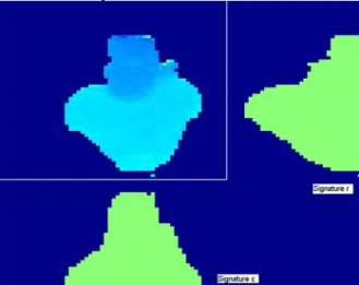
Figure 3. Image illustrating the ri and ci vectors
obtained out of an image.
3. Overview of the Recognition-Based
Tracking Algorithm
In the testing or tracking stage, each frame is processed to obtain its depth signature. First, the signatures in the training set are compared against the signature of the test frame. This provides a number of most likely matches. Next, a correlation metric is calculated between these and the test image. Finally, location of the head is determined via interpolation between the most likely matches using the correlation metric. Details are described next.
The algorithm has two main stages, a training stage, and a testing or tracking stage. In the training stage, long sequences of movies are captured from multiple people. A depth-signature is calculated on each frame as described in the following section. In addition, a window around the head location is manually identified on each frame. The training algorithm consists of a knowledge-based clustering algorithm. The resulting output is a set of good representative signatures for possible head locations.
4. Depth Signatures
Each depth image is processed to create a depth signature. Since the signatures are later used for tracking the position of the head, we need features that are sensitive to shape variations and translations. Specifically, a 134-dimensional feature vector, fi for
each image i Ii is created:
[
]
T i i i i i i m w r c f = σwhere mi and σi are the mean and standard deviation of
the depth values in Ii, wi is a vector that contains the
upper left and bottom right locations of the window around the head, and ri and ci are two vectors where
the jth values r
ij and cij are obtained as follows:
∑
> ∀ = 0 ) , ( , ) , ( k j I k i j i i k j I r , c∑
(
)
. > ∀ − = 0 ) , ( , ) , ( j k I k i j i i j k I KHere, Ii(m,n) is the value of the depth image at row m
and column n, and K is a constant. In other words, ri
and ci are modified row and column sums of the image
Ii. These vectors are illustrated in Figure 3. The
components ri and ci compress the whole depth image
into a vector of length equivalent to sum of the number of rows and columns. While doing so, it still keeps the relevant information in the depth image.
5. Training via Knowledge-Based
Clustering
Cluster-based learning is applied to the depth signatures. One possibility is to apply clustering or learning directly on the training set. K-means clustering or principal component analysis can be applied for this purpose. However, these approaches are diversely affected by the number of occurrences of cases. For instance, principal component analysis would treat a case that happens very infrequently as noise.
Instead, we apply clustering only after we divide the signatures into buckets of possible head locations. We use a modified vector quantization for this purpose. First, the image is divided into windows. Next, the signature of each training image is assigned into the window where the head is located in that image. After this assignment, each window contains a number of signatures.
Finally, signatures that fall in each window are clustered using k-means clustering. We apply an iterative k-means algorithm [17] where we start from a relatively large k, and iterate until each cluster has sufficient number of elements. At each iteration, we decrease k by eliminating the clusters with insufficient
number of elements. The signatures that are closest to the final cluster centers and the images associated with them are kept as the representative depth signatures and representative images to be used in signature matching and tracking.
6. Signature Matching and Correlation
Based Interpolation
Tracking consists of signature matching followed by correlation-based interpolation. First, the signature of the input depth image is obtained and compared with the signatures in the training set that remain after knowledge-based clustering. This provides best matches. It is possible that there are completely different configurations within these best matches. To avoid getting affected by bad matches, we apply correlation between the possible matches and the test image. Finally, we interpolate between the remaining matches to obtain the final head location.
The input is the depth image of the tracking scene. First, a signature of the input depth image is obtained as described in Section 4. Next, the signature is compared against the representative signatures that were obtained using knowledge-based clustering. Let fi
and fj be the signatures of the tracking image and a
cluster center respectively:
[
]
T i i i i i i m w r c f = σ[
j j j j j]
j m w r c f = σ TThe window of the previous tracked-frame is used as window wi. The distance Dij between fi and fj is
created as follows:
∑
∑
− − − + − − − + − + − + − = k j k j i k i k j k j i k i j i j i j i ij c M c sign c M c sign K r M r sign r M r sign K w w K K m m K D )) ( ( )) ( ( )) ( ( )) ( ( 5 4 3 2 1 σ σwhere sign() and M() are sign and median operations respectively, and K1...K5 are constants. Typical values
of these constants are 0.1, 0.1, 0.1, 1, 1 respectively. Once the distance Dij is obtained for every cluster
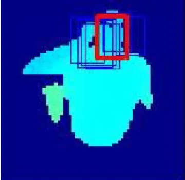
center j in the training set, the most likely detections are obtained as the cluster centers with a small distance Dij. Examples of possible detections are given in
Figure 4 with rectangles with thin edges. The possible detections are later evaluated by a correlation metric as described next.
Each possible location suggests a window wj for the
location of the head. Let Ii be the tracked depth image
and Ij be the image corresponding to a possible match
obtain the normalized depth image patches Ni and Nj respectively: ) , ( 1 ) , ( ) , ( , , I k l W n m I n m N j j w l k i j i w n m i
∑
∈ ∈ = ) , ( 1 ) , ( ) , ( , , I kl W n m I n m j j w l k j j j w n m j∑
∈ ∈ = Nwhere Wj is the number of elements in window wj. The
correlation metric Cij between the normalized image
patches Ni and Nj is obtained as follows:
Figure 4. Example of Possible Detections
∑
− = n m j i ij N mn N mn C , ) , ( ) , (Next, we provide examples of tracking frames from the three test movies in Figure 6, 7, 8 and 9 respectively. As one can see, there are various challenging configurations of the head. The system is able to track the head in these challenging configurations, such as the hand is in the image (Figure 6, and 8), or such as the head is partially occluded by the hand (Figure 8), or the head was barely visible due to lack of light (Figure 5) or where only a portion of the head is visible in the image (Figure 6 and 7), or where the head made extreme rotations (Figure 6 and 7). Sometimes, the head might be temporarily out of track when the head is out of picture or it is totally occluded. The system easily gets back into track when a good match is found between the training set and the test images.
Once the correlation metric for each possible detection j=1…n is determined, the location of the head location (w) is determined by an interpolation scheme given as follows:
(
)
(
)
∑
∑
= = = n j K ij K ij n j j K ij K ij C D w C D w 1 1 7 6 7 6where K6 and K7 are constants. Typical values are 1 to
5. In other words, the final detection w is an interpolated window between the possible matches. The interpolation is useful, since the training set does not necessarily cover all possible head locations, and interpolation assures that in-between configurations
can be constructed. To evaluate the performance of the algorithm, we calculate the area-wise overlap with the algorithm detection and the manually picked ground truth. We provide a curve for test movies where the subject was also part of our training set (Figure 10) and for test movies where the subject was not (Figure 11). The x axis is the amount of area-wise overlap, and the y-axis is the fraction that had at least that percentage of overlap (e.g. this is analogous to a cumulative probability function). On average, 60 percent overlap corresponded to a mismatch of 2 pixels in x and y on the head center. An 80 percent overlap corresponded a mismatch of 1 pixel in x and y on the head center. We observe robust results such that there is at least 70 (60) percent overlap on 85 (95) percent of the frames for the cases where the subject was also included in the training set (Figure 10). We also observe that there is at least 70 (60) percent overlap on 80 (90) percent of the frames for the cases where the subject was not included in the training set (Figure 11). All the processing was executed in real time using Microsoft Visual C/C++ on a Pentium 3 Processor.
7. Experiments and Results
We have conducted experiments on a set of 10 sequences with 8 people, for a total of 2287 depth frames. We used the Canesta time-of-flight depth sensor, which provided 64x64 depth images at a frame rate of 30 fps. Next, we constructed a training set from the set of movies. We obtained signatures for each frame in the movies, which we clustered into 1443 frames. These included cases at 274 different head locations in the image.
Then, we constructed a testing set with movies from six people that also had movies in the training set, and two people that did not have any movies in the training set. We manually chose the head location in each image so that we could compare the experiment results with the manually selected ground truth.
Figure 5 shows the benefits of interpolation: possible head locations are identified by the thin lines, and the resultant head location by the thick line. This corrects satisfactorily for wrong initial matches, and for cases where the exact location does not exist in the training set.
8. Conclusions
[8] S.B. Gokturk, J.Y. Bouguet, R. Grzeszczuk, “A data driven model for monocular face tracking”, ICCV, 2001, 701-708.This paper illustrated the use of a time-of-flight depth sensor for a head tracking application. In our problem, we aimed to obtain a robust head-tracking algorithm that would track challenging cases such as various configurations that involved the head and the hand, partial occlusions, partial out of image positions.
[9] S.B. Gokturk, J.Y. Bouguet, C. Tomasi, B. Girod, “Model-Based Face tracking for View-Independent Facial
Expression Recognition”, IEEE In.l Conf. on Face and
Gesture Recognition , 2002, 272-278.
[10] S. Birchfield, “Elliptical Head Tracking Using Intensity Gradients and Color Histograms”, CVPR, 1998, 232-237. Our algorithm applies recognition followed by
interpolation. We use a knowledge-based training algorithm, where the data is first divided into initial clusters depending on where the head is located at the particular frame. Then, a modified k-means clustering is applied to cluster the data in the initial cluster. Knowledge-based clustering assures that all possible cases are accounted for in the training set.
[11] R. Yang and Z. Zhang: "Model-Based Head Pose Tracking Using Stereovision", IEEE In.l Conf. on Face and Gesture Recognition , 2002, 242-247.
[12] S.Malassiotis and M.G.Strintzis: "Real-time Head Tracking and 3D Pose Estimation from Range Data", ICIP 2003, 859-862.
[13] C. Tomasi, S. Petrov and A. Sastry. 3D tracking = classification + interpolation. ICCV, 2003, 1441-1448.
While testing a new frame, we first find a set of possible matches from the training set. Due to the complexity of the head/body configurations, it is possible that there are wrong matches. We calculate a correlation metric between the possible matches and the test image, for use in the final interpolation.
[14] S. K. Nayar, S. A. Nene, and H. Murase, “Subspace Methods for Robot Vision”, IEEE Trans RA, 1996, 12(5) – 750-758.
[15] C. Bamji, “CMOS Compatible 3-D Image Sensor”, U.S. Patent No: 6,323,942.
[16] C. Bamji, E. Charbon, “CMOS Compatible Three-Dimensional Image Sensing Using Reduced Peak Energy”, U.S. Patent No:6,580,496.
The paper makes various contributions. First, we suggest using the depth images for robust head-tracking, since it is easier to infer geometry and 3D location from depth images. Next, we provide a fast recognition and interpolation based head tracking algorithm. This algorithm is robust in various configurations, since it never gets into a local search deadlock when the track is temporarily lost. The proposed signatures work best for depth images, although the general framework of recognition based tracking is applicable to intensity images with the appropriate choice of signatures.
[17] S.B.Gokturk, “Shape Recognition with Application to Medical Imaging”, PhD Thesis, Stanford University, 2002.
Figure 5. Examples of interpolation. Correlation based metric helps avoiding distraction by initial mismatches.
10. References
[1] B.D. Lucas, and T. Kanade, “An iterative image registration technique with an application to stereo vision“,Proc. 7th IJCAI, 1981, 674-679.
[2] J. Shi, C. Tomasi, Good Features To Track, CVPR , 1994, 594-600.
[3] J. Barron, D. Fleet, D. and S. Beauchemin, “Performance of optical flow techniques”, IJCV, 1994, 43-78.
[4] D. DeCarlo, and D. Metaxas, “Deformable model-based face shape and motion estimation”, Proc. 2nd Int.l Conf. on Automatic Face and Gesture Recognition, 1996, 146-150. [5] D. DeCarlo, and D. Metaxas, ”The Integration of Optical Flow and Deformable Models with Applications to Human Face Shape and Motion Estimation”, CVPR, 1996, 231-238. [6] P. Eisert, and B. Girod, “Model-based Facial Expression
Parameters from Image Sequences”, Proc. IEEE
International Conference on Image Processing, Santa Barbara, CA, USA, 1997, 418-421.
Figure 6. Tracking results from a movie. Frames – 1, 17, 22, 27, 58, 93. The head is successfully tracked in various distance and location of the head.
[7] P. Eisert, and B. Girod, “Analyzing Facial Expressions for Virtual Conferencing”, IEEE Comp. Graphics and Appl., Computer Animation for Virtual Humans, 1998, 70-78.
Figure 7. Tracking results on another movie. Frames – 1, 4, 18, 44, 53, 79. The head is tracked in instances where the head is mostly out of picture, or where the hand is in the picture, providing confusing configurations.
Figure 10. Performance curves from test movies where the subject was also participating in training movies. Each curve corresponds to another test movie.
Figure 8. Tracking results on another movie. Frames 8, 15, 50, 63, 92, 132. The head is tracked under extreme rotations.
Figure 11. Performance curves resulting from test movies where the subject was not participating in training movies. Each curve corresponds to another test movie.
Figure 9. Tracking results on another movie. The head is partially occluded by the hand on these frames.