AIAA-98-2506
Experimental Supersonic Combustion
Research at NASA Langley
20th AIAA Advanced Measurement
and Ground Testing Technology
Conference
June 15-18, 1998/Albuquerque, NM
R.C. Rogers, D.P. Capriotti, R.W. Guy
NASA Langley Research Center,
Hampton, VA
Drag
AIAA 98-2506
EXPERIMENTAL SUPERSONIC COMBUSTION
RESEARCH AT NASA LANGLEY
R. Clayton Rogers* Diego P. Capriotti†, and R. Wayne Guy
‡NASA Langley Research Center
Hampton, VA 23681
Abstract
Experimental supersonic combustion research related to hypersonic airbreathing propulsion has been actively underway at NASA Langley Research Center (LaRC) since the mid-1960’s. This research involved experimental investigations of fuel injection, mixing, and combustion in supersonic flows and numerous tests of scramjet engine flowpaths in LaRC test facilities simulating flight from Mach 4 to 8. Out of this research effort has come scramjet combustor design methodologies, ground test techniques, and data analysis procedures. These technologies have progressed steadily in support of the National Aero-Space Plane (NASP) program and the current Hyper-X flight demonstration program. During NASP nearly 2500 tests of 15 scramjet engine models were conducted in LaRC facilities. In addition, research supporting the engine flowpath design investigated ways to enhance mixing, improve and apply nonintrusive diagnostics, and address facility operation. Tests of scramjet combustor operation at conditions simulating hypersonic flight at Mach numbers up to 17 also have been performed in an expansion tube pulse facility. This paper presents a review of the LaRC experimental supersonic combustion research efforts since the late 1980’s, during the NASP program, and into the Hyper-X Program.
_________________
*Aerospace Engineer, Hypersonic Airbreathing Propulsion Branch, Senior Member AIAA.
†Aerospace Engineer, Hypersonic Airbreathing Propulsion Branch, Member ASME.
‡
Head, Hypersonic Airbreathing Propulsion Branch, Senior Member AIAA.
Copyright © 1998 by the American Institute of Aeronautics and Astronautics, Inc. No copyright is asserted in the United States under Title 17, U. S. Code. The U.S. Government has a royalty-free license to exercise all rights under the copyright claimed herein for Governmental Purposes. All other rights are reserved by the copyright owner
.
Nomenclature
A Area
D Diameter
G Combustor gap height H Enthalpy; duct height
M Mach number
P Power
p Pressure
Q Volumetric flow rate q Dynamic pressure R Nozzle corner radius
T Temperature
X Axial coordinate
∆F Fuel-on minus fuel-off axial force
α Volumetric ratio
φ Equivalence ratio
Subscripts:
1 Facility test gas; scramjet inflow max Maximum value
t Stagnation condition Flight condition
Acronyms and Abbreviations:
8-Ft. HTT 8-Foot High Temperature Tunnel AIM Aerothermodynamic Integration Model AIS Airframe-Integrated Scramjet
AHSTF Arc-Heated Scramjet Test Facility AR Nozzle area ratio
CDE Concept Demonstration Engine CFD Computational Fluid Dynamics CHSTF Combustion-Heated Scramjet Test
Facility
DCSCTF Direct-Connect Supersonic Combustion Test Facility DFX Dual-Fuel, eXperimental engine FE Hyper-X Flight Engine
FFS Full-Flowpath Simulator FPI Fuel Plume Imaging
HRE Hypersonic Research Engine HSM HYPULSE Scramjet Model HXEM Hyper-X Engine Model HXRV Hyper-X Research Vehicle HYPULSE HYpersonic Pulse facility LaRC Langley Research Center LSTC Langley Scramjet Test Complex NASP National Aero-Space Plane P&W Pratt and Whitney
RD Rocketdyne
RST Reflected-Shock Tunnel SAM Structural Assembly Model SERN Single-Expansion Ramp Nozzle SETb Shock-Expansion Tube
SETn Shock-Expansion Tunnel STF Scramjet Test Facility
SXPE Subscale eXperimental Parametric Engine
SX-20 Subscale eXperimental, engine 20 VPI Virginia Polytechnic Institute X-30 NASP Experimental Vehicle
Introduction
Supersonic combustion research at the NASA Langley Research Center (LaRC) began in the 1960’s with analytical studies and some fundamental experiments. The rationale for studying supersonic combustion has always been with application to airbreathing propulsion, specifically supersonic combustion ramjets (scramjets). With the support of contracted efforts, this basic experimental research led to the Hypersonic Research Engine (HRE) project, which was started about 1964.1,2 Although the HRE did not achieve the original intent of a test flight, the idea of hypersonic flight in the atmosphere with airbreathing propulsion systems has been continually pursued through experimental and computational research at LaRC. These research efforts were focused on the clear need to achieve good installed performance with a propulsion system integrated into the vehicle flowpath. The airframe-integrated scramjet (AIS) concept3 became the basic flowpath for both fundamental studies of fuel injection, mixing, and combustion, and for subscale engine tests in both LaRC and contractors’ facilities. A review of this baseline research, including a summary of scramjet engine design methodology and test techniques as of 1985 and an extensive bibliography has been documented in reference 4.
The review4 of the scramjet technology in the mid-1980’s indicated a firm fundamental basis for the
performance potential of dual-mode scramjets. A dual-mode scramjet is designed without the conventional ramjet second minimum area for operation in both subsonic (ramjet) and supersonic combustion modes. This fundamental level of understanding was obtained from scramjet research that included established ground test techniques for scramjet flowpaths and components, maturing computational fluid dynamic (CFD) methods, and measurement diagnostic systems. Supporting the engine flowpath ground tests were component tests and CFD analyses of inlets, fuel injection and mixing, combustion chemical kinetics and flameholding, and turbulence modeling which included combustion effects. Fuel injection and mixing studies were done in both cold flow and direct-connect combustion environments. These studies included the investigation of scramjet combustor concepts with fuel injection parallel to the flow from the base of ramps.5 Although ground tests of scramjet components and engines were limited by facility operation to the mid-speed range of flight Mach 4 to 8 simulation, some small scale tests of hydrogen-air mixing and combustion had been done at hypervelocity flow conditions simulating flight at Mach 12 to 18. These tests,6 which were conducted in pulse flow facilities where the test gas is heated and processed by a shock wave, indicated the potential for scramjet operation in hypersonic flight above Mach 10.
Drawing on the extensive technology base available in the mid 1980’s, the National Aero-Space Plane (NASP) program began and became the focus for maturing and applying this scramjet technology to a proposed flight research vehicle capable of trans-atmospheric flight. Associated with this renewed national interest in scramjets was a need for ground test facility capabilities that spanned the flight regime.7 The outcome of NASP was a significant leap in scramjet knowledge, both in the form of scramjet engine test techniques and a database in the mid-speed flight (Mach 4 to 8) range of conventional ground test facilities, and in the flight Mach 12 to 18 simulation tests in shock tunnel facilities. With the end of the NASP program in 1995, the hypersonic propulsion emphasis at LaRC shifted to assessment of the NASP database and providing scramjet flowpath design, testing, and operation support for the Hyper-X Program.8 The Hyper-X Program will demonstrate the free-flight operation of an airframe-integrated, hydrogen-fueled, scramjet flowpath in atmospheric flight at Mach 7 and 10 between now and 2002.
The major LaRC contributions to supersonic combustion technology and the application of scramjets in hypersonic airbreathing propulsion systems have been engine flowpath testing, ground test technique capability, and development of computational tools to benchmark the design methods and provide data analysis tools. However, research activities have continued to examine fuel injection schemes to enhance fuel-air mixing and to study alternative or combined cycle propulsion systems. The purpose of this paper is to provide a review of experimental supersonic combustion research efforts related to airbreathing propulsion systems at LaRC since 1986. The paper will begin with an historical overview (including a summary of the 1986 paper4), review the scramjet test facilities used and engine tests conducted during the NASP program, summarize the scramjet component tests, and conclude with an overview of current experimental research activities.
Historical Perspectives
Any discussion of experimental supersonic combustion research at LaRC must involve its application to scramjets for hypersonic airbreathing propulsion. For nearly forty years, scramjet research activities at LaRC have progressed from the supporting technology that led to the Hypersonic Research Engine (HRE) project to the current flight test program called Hyper-X. A review of scramjet research and progress worldwide is given in reference 9.
Scramjet Base Research:
The history of scramjet technology development at LaRC is depicted by the time line in Figure 1. The time line shows a continuous path of Base-Research, which supported focused efforts like the HRE project from 1964 to 1974, the NASP program from 1987 to 1995, and the Hyper-X flight demonstration program, ongoing since 1996. Key “Technology Areas” which were being studied or developed are listed above the line, generally in chronological order. Below the time line are highlights of “Test Experience.” Important testing events or milestones are indicated and include scramjet test facilities (STF) coming on-line and engine flowpath test programs. Specific events of note are the airframe-integrated scramjet (AIS) concept in 1968, which was the basis for almost all of the subsequent supersonic combustion
research, and the fuel-air mixing scramjet combustor design recipe, which was first presented and discussed in 1986.4 The variety and type of engine tests conducted are indicated by the ovals in the timeline; those which were directly supportive of the NASP program are indicated within the NASP oval.
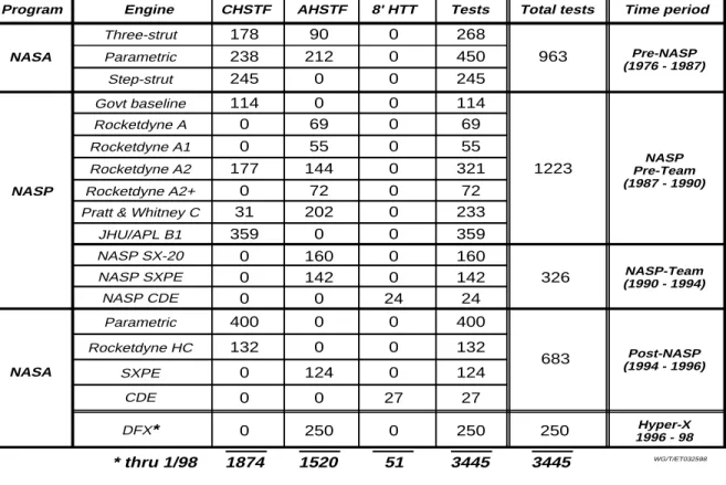
All of the tests of scramjet engine flowpaths conducted in LaRC STF facilities from 1976 to the present are summarized in Table 1.10 Engine test activity accelerated dramatically in support of NASP and continued after NASP to provide closure on open questions and concerns. Currently, testing is underway to provide Mach 5 and 7 technology support to the Hyper-X Program. To date, 3445 tests have been conducted on 18 scramjet engine models in numerous flowpath configurations, at mid-speed (flight Mach 4 to 8) conditions in LaRC facilities. Assuming an average test condition simulating Mach 5 flight speed (about one mile per second) and a nominal test duration of about 20 seconds of on-point data (typical for the STF’s), these tests are equivalent to about three trips around the world in scramjet operational experience.
Basis for NASP:
The year 1986 provides a distinct break point in the discussion of scramjet research because of the review documented in Reference 4, and the beginning of the NASP program. That review of the ground test and supporting research on the modular, airframe-integrated, dual-mode scramjet flowpath presented a summary of the direct-connect tests of scramjet combustor components and engine flowpath tests (see Table 1), and included an extensive bibliography from LaRC and other groups. The original concept for scramjet combustors was to inject hydrogen fuel into the supersonic air stream from orifices flush mounted on the walls or on the sides of struts, which also provided internal inlet compression.3,11 Examples of the types of scramjet engine flowpath hardware used to study scramjet operation in the 1976-87 period are shown in cross section views in Figure 2. These engines are all of the modular concept, with sidewall compression, for operation between Mach 4 and 8 flight. Shown in the figure are the “three-strut engine,” the “strutless parametric engine,” and the “step-strut engine.” Tests were conducted as indicated in Table 1. The outcome of these tests helped establish the Langley scramjet combustor design methods.4
The thrust performance results from tests of these engine configurations at simulated flight at Mach 4 and 7 are summarized in Figure 3. The solid lines are theoretical predictions from streamtube analyses using an empirical fuel mixing schedule based on numerous direct-connect test results. Also shown are estimates of vehicle drag. The performance potential demonstrated in these ground test results, the confirmation of design methods, the LaRC supersonic combustion ground test experience and capability, and the application of analytical tools and models, contributed significantly to the decision to proceed with the NASP program. The contribution and collaboration of other government research programs sponsored by the Navy and Air Force culminated in the initiation of the NASP program in 1987.
The NASP Era
During the NASP program, the majority of scramjet work at LaRC involved engine flowpath tests, as indicated in Figure 1 and listed in Table 1. Ten engine models in multiple configurations were studied in 1549 tests from 1987 to 1994. However, basic research studies of scramjet phenomena continued. These studies included transverse fuel injector operation,12,13 injector concepts for fuel mixing enhancement,14-17 application of nonintrusive measurement systems for supersonic combustion,18-20 and nozzle performance effects.21,22 Ground test capability at true flight stagnation enthalpy also was needed to simulate the hypervelocity conditions of trans-atmospheric flight. This need led to the reactivation of several pulse facilities, among which was the NASA HYpersonic PULSE (HYPULSE) shock-expansion tube (SETb), that came on-line in 1988.23-25
The remaining sections of this paper will include highlights of the experimental supersonic combustion work at LaRC from 1986, including a review of the test facilities, engine flowpath tests, scramjet component tests and supporting research, and some areas of experimental scramjet research of current interest.
Test Facilities
.
Schematic diagrams of the five major test facilities that comprise the Langley Scramjet Test Complex (LSTC) are presented in Figure 4. Details of the facilities’ operation, instrumentation, and usage are presented in Reference 10. All of the facilities
are located at LaRC except for the HYPULSE facility, which is located at and operated by GASL, Inc. under contract to NASA. A summary of the test facilities is given in Table 2, which includes information about the flow heating method, nozzle exit size, and test section dimensions. The altitude-flight Mach number operational envelopes of the LSTC facilities are given in Figure 5. Included on the map are lines of constant stagnation pressure and enthalpy and lines of dynamic pressure along the airbreathing flight corridor.
Engine Test Facilities:
The Arc-Heated Scramjet Test Facility (AHSTF), has been in operation since 1976.26 The test gas is obtained by heating air with an electric arc (up to 13MW), and adding unheated air to achieve the desired stagnation pressure and enthalpy. The facility can replicate the stagnation enthalpy conditions of scramjet captured air at flight Mach numbers from 4 to 8. Maximum facility stagnation pressure is about 40 atm. Typical run times vary between about 60 to 30 seconds at flight Mach 4 and 8 conditions, respectively.
The Combustion-Heated Scramjet Test Facility (CHSTF),27 in operation since 1978, uses a vitiated-air test gas which is obtained by hydrogen combustion, with oxygen replenishment to keep the oxygen concentration at 21%. The facility can deliver a test gas at stagnation enthalpy simulating Mach 3.5 to 6.0 flight speeds. Maximum facility stagnation pressure is 34 atm. Typical run times are 25 seconds duration.
The 8-Foot High Temperature Tunnel (8-Ft. HTT) was upgraded for propulsion testing in 1993 with the provision for oxygen replenishment of the methane combustion-heated test gas.28 The facility test conditions can simulate Mach 4 to 7 flight enthalpy. Maximum facility stagnation pressure is about 136 atm. at Mach 7. Typical run times are about 30 seconds on point. Calibration information for scramjet testing is provided in Reference 29.
Component Test Facilities:
The Direct-Connect Supersonic Combustion Test Facility (DCSCTF) is a parallel test cell with the CHSTF and has been the site for testing scramjet fuel injectors, combustor configurations, inlet isolators, and nozzle expansions since the late
1960’s. The vitiated-air test gas is produced by hydrogen combustion in air with oxygen replenishment to keep the test gas oxygen content at 21%. Stagnation conditions are limited to about 40 atm. and 2100K (3800 R), which corresponds to flight Mach 7.5.
Hypervelocity Testing:
The NASA HYPULSE facility,23 operating in the shock-expansion tube (SETb) mode, provides hypervelocity test capability for fuel injectors and combustors at simulated flight conditions from Mach 12 to 17. In this mode of operation, the test gas is heated and accelerated by a shock wave to the static flow conditions corresponding to scramjet combustor entrance at the desired flight Mach number.
Recently, HYPULSE has been upgraded to increase the operational flight envelope in Mach number and dynamic pressure simulation.30-33 The upgrade included the installation of a 175:1 area ratio (AR) axisymmetric nozzle, with an exit diameter of 66.67 cm (26.25 inches), which enables operation as a reflected shock tunnel (RST) for scramjet engine testing at simulated conditions from about flight Mach 5 to 12. The new test section for scramjet engine testing is shown in the sketch in Figure 6. The expanded test envelope is shown in Figure 5, denoted HYPULSE-RST. Conditions at the exit of the AR-175 nozzle are given in Table 2. These conditions overlap the test envelopes of the other blowdown STF’s, and will provide testing at Mach 10 in support of Hyper-X. Although not yet fully implemented, the upgrade offers the potential for HYPULSE operation in a shock-expansion tunnel (SETn) mode for scramjet engine tests at simulated flight speeds from Mach 12 to 18+. Because test times are short, on the order of a few milliseconds, the test hardware remains cold, and optical diagnostics of the combustor internal flow are easily implemented.
Engine Tests
Scramjet engine flowpath tests conducted in LSTC facilities are listed in Table 1. Much of the data and results have limited access, which prevents discussion of the test details. Prior to the NASP program, 963 tests were conducted on three engine configurations over a twelve-year period. During the NASP program, testing increased dramatically with 1549 tests conducted on ten engine models and numerous configurations over
a four-year period. After NASP ended, NASA-led testing of NASP engine models, the SXPE and CDE, continued with 151 tests conducted. In addition, 400 tests were conducted using the LaRC Parametric Engine, and 132 tests were conducted using a Rocketdyne NASP engine modified for hydrocarbon fuel (ethylene). Recently, in support of the Hyper-X program, over 250 tests have been completed using the DFX engine installed in the AHSTF. Quantities typically measured in these tests include wall pressures, wall heat transfer, net axial force, mass flow rates, and in-stream pitot pressures. The sub-scale engine models are typically non flight-weight test articles of heat sink thermal design.
General subscale engine testing methodology34 is depicted in Figures 7 and 8. Figure 7 illustrates the typical operation of a dual-mode AIS in the mid-speed (flight Mach 4-8) regime (where transition from subsonic to supersonic burning occurs), and identifies the associated physical processes of importance. The vehicle sketch inset in the figure shows the concept of airframe-integrated modular engines. The elements key to this discussion are the fuel injection, mixing, and combustion, and the isolation of the heat release process from the internal inlet operation. Replication of these processes in a ground test is illustrated in Figure 8, where the principal simulation parameters are stagnation enthalpy (at the flight Mach number), and Mach number and static pressure entering the engine. Typical ground test facilities simulate the compression process due to the vehicle forebody by heating the test gas to the stagnation enthalpy corresponding to the flight Mach number, and then expanding the test gas to the lower aerodynamic Mach number approaching the inlet of the engine. Typically, the stagnation enthalpy and inflow Mach number will be matched, but the inflow static pressure may be low, which corresponds to a lower dynamic pressure simulation. In general, the goals of subscale engine tests are to determine engine operability, inlet performance, isolator performance, fuel-air mixing and flameholding, combustion efficiency, and to maximize the measured thrust stand performance, ∆F.
Pre-NASP
Prior to the NASP program, scramjet combustion research at LaRC focused upon the three-dimensional, fixed-geometry sidewall compression engine concept. This engine utilized swept wedge sidewalls to compress the flow with various fuel injector and flameholder designs. Three different
configurations of this engine were tested (see Figure 2): the three-strut, the strutless parametric and the step-strut. The three-strut engine was a rectangular (swept) sidewall compression engine. Three internal swept struts further compressed the captured test gas and injected hydrogen fuel into the flow. The parametric engine was a versatile test article, which was changed into different configurations without removal from the test facility. The parametric engine was rectangular and used a sidewall compression inlet. The step-strut engine was the parametric engine with the sidewall leading edges unswept and a swept strut with a "stepped" leading edge. Test results achieved with these engines contributed to the beginning of the NASP program, as previously indicated.
NASP, 1987-1990
The first scramjet engine model built and tested during the NASP program was the Government Baseline engine, which had 114 tests in various configurations in the CHSTF at simulated flight Mach 4 conditions. The objective of these tests was to identify any major problems with the ramjet/scramjet engine cycle that would hinder the progress of the NASP program. The government baseline engine had variable-geometry that allowed the engine to be tested as a classic mechanically throated ramjet. This engine achieved fuel ignition by using conventional spark plugs rather than the pyrophoric 20% silane in hydrogen fuel mixture of most of the subsequent engine tests.35
During these early years of the NASP program, independent scramjet engine designs were tested in the CHSTF and AHSTF by the major engine companies (Pratt & Whitney (P&W) and Rocketdyne (RD)) in order to create a dual-mode scramjet. A total of 517 tests were completed using the Rocketdyne "A" series of engines in both LSTC facilities. (See Table 1.) The P&W engine “C” had 233 tests in the same two LSTC facilities. A photo of this engine installed in the CHSTF is shown in Figure 9. Also during this period, 359 tests were conducted in the CHSTF of the Generic High Speed Engine (GHSE) model B-1, which was designed by the Johns Hopkins University Applied Physics Laboratory (JHU-APL). The GHSE was a rectangular engine composed of an opposed dual-ramp inlet, an isolator, and a combustor with a constant area section followed by a diverging section.36 Tests were conducted at simulated flight Mach numbers of 4.3 and 5.0. The RD, P&W, and
JHU/APL engine tests were all focused towards demonstration of high performance and good operability characteristics in the mid-speed flight range with engine flowpaths designed for trans-atmospheric flight.
NASP, 1990-1994
The first engine built and tested following teaming of the NASP engine contractors (1990) was the SX-20 (Subscale eXperimental-engine 20). Tests of this engine in various configurations were conducted in the AHSTF at simulated flight Mach numbers of 7 to 8. Results of these and other engine and engine component tests influenced the final NASP engine design, which was intended to power the X-30 experimental airplane. A 12.5% scale version of this engine flowpath was constructed and named the Subscale eXperimental Parametric Engine, (SXPE). Tests of this engine were conducted in the AHSTF at simulated flight Mach numbers of 5 to 8.
A larger engine, the Concept Demonstration Engine (CDE), was built for testing in the 8-Ft. HTT. The CDE flowpath was designed for high speed flight up to Mach 25. The CDE test engine was of heat-sink thermal design that was a 30% photographic scale of the middle module of the NASP X-30 engine flowpath. Twenty-four tests of the CDE were conducted in the 8-Ft HTT at a simulated Mach 7 flight condition, but at 60% of the flight dynamic pressure. The test objectives were to demonstrate performance and operability limits of the large-scale integrated scramjet in order to verify flowpath design methods for application to flight.
Figure 10 shows a schematic representation of the geometric relationship between the CDE, SXPE, and the X-30 flight engine flowpaths, and includes the available ground test simulation parameters relative to the flight environment at Mach 7. The figure shows that although each facility was able to simulate the correct flight stagnation enthalpy, the simulated flight dynamic pressures were low, and consequently, the Reynolds number simulations of both facilities were low when compared with flight. In addition, the test gases of the facilities contain contaminants-- water vapor and carbon dioxide in the 8-Ft. HTT and small amounts of NOx in the AHSTF. Some discussion of the issues of ground test simulation regarding the X-30 engine, the CDE, and the SXPE is given in Reference 34. The SXPE and CDE tests provided a direct comparison of essentially the
same supersonic combustor flowpath at two geometric scales in two facilities from which ground test simulation concerns could be examined. These concerns include the effects of simulation parameters relevant to scramjet engine flowpath operation, including the Mach, Reynolds, and Stanton numbers, first and second Damkohler numbers, and wall enthalpy ratio.37 The outcome from the two test series indicated the need to understand the effects of geometric scale, dynamic pressure, facility test gas composition, and viscous effects when designing and testing scramjet engines for hypersonic flight.
Post NASP
Testing of the SXPE and CDE engines continued after the end of the NASP program to further investigate specific performance characteristics and to gain an understanding of the differences observed in the test data. During this effort, 124 tests were conducted with the SXPE installed in the AHSTF and 27 tests were conducted with the CDE installed in the 8-Ft HTT.
Following the NASP tests, a NASA test program was initiated to investigate fundamental issues governing dual-mode scramjet engine performance. The test article chosen for this program was the LaRC Strutless Parametric Engine. This engine model was installed in the CHSTF and 400 tests were conducted in various configurations to examine inlet-combustor interaction, captured airflow profile, and test gas contamination effects. The engine was tested with two different sidewall compression inlets having the same projected full capture area. One inlet had both sidewall leading edges swept backward and the other had one sidewall leading edge swept forward and the other backward. Tests were conducted over a simulated flight Mach number range of 4.0 to 5.5 with inlet contraction ratios of 5 and 6. During some tests, ingestion of the vehicle forebody boundary layer was simulated by testing with the engine capturing the facility nozzle boundary layer. The engine was tested as a classic mechanically throated ramjet, and as a thermally throated dual mode scramjet. Hydrogen fuel was injected from various locations through sonic perpendicular sidewall orifices. Additional details of these tests are documented in Reference 38.
Although most all testing at LaRC has been conducted using hydrogen fuel, some operation of hydrocarbon-fueled scramjets has been
explored.39 That investigation reports on tests of a RD engine model in the CHSTF using ethylene as a generic hydrocarbon fuel. Test conditions simulated flight Mach 4 (stagnation temperature 911K (1640 R)) at 1000 psf dynamic pressure. Tests were conducted with fuel injected from several discrete locations and in combinations with other injectors to assess thrust performance and combustor-inlet interaction. For comparison with selected ethylene tests, some tests were made with hydrogen fuel.
The hydrocarbon engine testing included an assessment of: 1) fuel ignition and flameholding, 2) injector location, 3) pilot gas quantity on performance, and 4) fuel type on performance. A 20/80% (molar) mixture of pyrophoric gas (silane and hydrogen) was used for ignition of the fuel. However, results of the tests indicated that, for the scale and conditions of the tests, combustion with ethylene fuel required piloting with the silane fuel mixture. Hydrogen fuel operation was achieved unpiloted, using the silane fuel mixture for ignition only. A comparison summary of these results is shown in Figure 11. The performance parameter
∆F is the difference in the measured loads on a force balance between fuel-on and fuel-off operation. The performance achieved with piloted combustion of ethylene and systematic variation of fuel injection was comparable with the best performance for hydrogen fuel.
Scramjet Component Tests
DCSCTF:
Experimental tests of supersonic combustor components have been conducted using direct connect hardware to acquire data to study basic combustor performance for simple geometries and to explore diagnostics. The following sections give examples of some of these activities.
Plasma Torch. -- Tests to study the application of a plasma torch as an ignition source for hydrogen-fueled supersonic flow fields were conducted at nominal Mach 2 and one atmosphere static pressure combustor entrance conditions, simulating about flight Mach 4 (Tt = 780 - 1000K
(1400 - 1800R)).40,41 Figure 12 shows a schematic diagram of the combustor duct. The five 0.05-inch diameter, perpendicular injectors, supplied a small amount of hydrogen fuel to pilot the flameholding region behind the 0.15-inch high step. The three 0.1-inch diameter perpendicular injectors, located
downstream of the step, fueled the scramjet combustor duct. The plasma torch, shown in Figure 13, was installed in the separated flow region downstream of a rearward-facing step. The plasma torch was designed to operate with a gaseous mixture of argon and hydrogen at power levels of approximately 1kW. The mixture was supplied to the plasma torch at various volumetric ratios (α). The mass flow through the torch was approximately 0.01 percent of the total mass flow through the test article, with the hydrogen flow comprising only 0.1 percent of the total fuel flow. Nominal fuel equivalence ratios for the upstream and downstream injectors were 0.042 and 0.26, respectively. Pressure data on the top and bottom walls were used to estimate the combustion efficiency as a function of facility and plasma torch parameters.
Figure 14 shows a plot of the measured pressure distributions for tests without fuel injection, for hydrogen-fueled tests with the argon-hydrogen plasma, and for two tests with different amounts of a pyrophoric fuel mixture (20% silane (SiH4) in
hydrogen). This silane fuel mixture was injected from an orifice at the same location and of similar size to the plasma torch. The pressure distributions for the fueled tests are quite similar, indicating that the ignition and flameholding characteristics for the argon-hydrogen plasma are similar to those with the pyrophoric fuel mixture. However, the data indicated that the pyrophoric fuel mixture was only able to ignite the primary fuel for facility stagnation temperatures greater than 990K (1780R), whereas the argon-hydrogen plasma was able to ignite the primary fuel for all stagnation temperatures tested, 290 to 990K (520 - 1780 R). Results of the test series indicated that the argon-hydrogen plasma torch was an effective igniter for a scramjet combustor when used in conjunction with flameholder geometry.
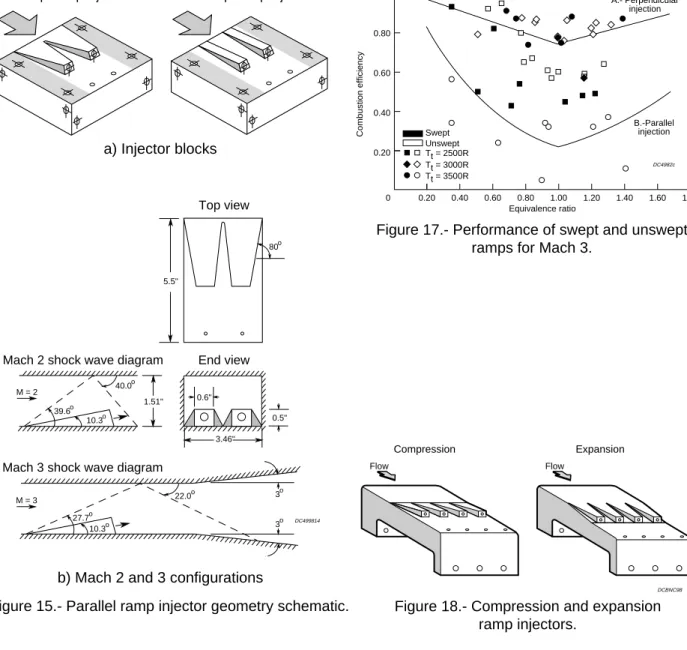
Swept-Ramp Injectors. -- Mixing and combustion characteristics of wall-mounted ramps with base fuel injection were studied in the DCSCTF at conditions simulating Mach 5 to 7 flight.14-16 The objective of the tests was to explore the enhancement of the fuel/air mixing and thus reduce the length of a scramjet combustor. Since fuel injection directed downstream is useful to extract energy from hydrogen fuel that has been used to cool the engine and airframe, techniques to enhance the relatively slow mixing of parallel fuel jets were investigated. The tests were conducted at Mach 2 and 3 combustor entrance conditions and the hydrogen fuel was injected at
Mach 1.7 from the bases of swept and unswept wall-mounted ramps. As shown in Figure 15, the ramps were inclined 10 degrees relative to the wall. During all test series, the simulated flight Mach number was varied from 5 to 7 by changing the facility stagnation temperature. The exit static pressure was maintained at 1 atmosphere with the Mach 2 nozzle and 12 psia with the Mach 3 nozzle. Also shown in Figure 15 are a schematic of the ramp fuel-injector geometries and sketches indicating the shock positions for the two combustor entrance Mach numbers tested. Additional information about the design and testing is available in the cited references.
One-dimensional analyses of the wall pressure data were performed to determine the combustion efficiency distributions that are shown in Figures 16 and 17 as a function of fuel equivalence ratio for the Mach 2 and Mach 3 tests, respectively. For comparison, the curves labeled A and B indicate the predicted mixing performance using the Langley mixing model. Curve A is for perpendicular sonic injection and Curve B is for parallel sonic injection. The combustion and mixing efficiencies shown in Figures 16 and 17 were calculated at an X/G of 12.5 to be consistent with the model definition of gap height, G, which is defined as the combustor height at the injector location. At the Mach 2 condition, the performance of the swept injectors (Fig. 16) was nearly equal to the mixing predicted by the perpendicular injection mixing model; however, the performance of the unswept injectors was closer to the parallel injection mixing model. It was observed also that the swept injectors do not show a dependence on the facility stagnation temperature whereas, the unswept injector results indicated decreasing performance as the stagnation temperature was increased.
For the Mach 3 tests (Figure 17), the swept injector performance equaled and surpassed the mixing model predicted values for perpendicular injection (curve A) with facility test gas at Tt = 1670
- 1900K (3000 - 3500R). The poorer calculated combustion efficiency for the unswept injectors at Tt = 1940K (3500R) suggests an absence of a
flame-holding region at the ramp base. This lack of flameholding could be attributed to the near matching of the fuel jet and test gas velocities at this test point.15 However, the unswept injectors performance was nearly equal to the mixing model prediction for the perpendicular injection at the lowest facility temperature tested (1390K
(2500R)), and surpassed the model for the middle total temperature tested (1670K (3000 R)).
Expansion-Compression Ramps. -- Tests of expansion and compression ramp injectors, as shown in Figure 18, were conducted.18 The compression ramp injector block had 10-degree swept ramps that reduced the flow area by about 12% (CR = 1.14) at the ramp base. The expansion ramp injector had 10-degree expansion surfaces of increasing width between flush-wall injector ramps, that increased the flow area by about 21.5%. Each ramp sidewall was swept at a 10-degree angle, ending with a 0.6 inch wide by 0.5-inch high base. For the compression ramp injectors, the ramp and fuel injection angle were both 10.3 degrees. All other dimensions of the expansion ramp injectors are the same as the compression ramp injectors. Hydrogen fuel was injected from the ramp bases through Mach 1.7 nozzles. Tests were conducted at facility stagnation temperature and pressure of 1940K (3500R) and 27.9 atm., respectively, using a Mach 2.7 nozzle to simulate the scramjet combustor entrance flow. Static pressure at entrance to the combustor model was one atm. A side view of the combustor duct for the compression ramp configuration is shown in Figure 19. The two-dimensional duct was a constant width of 6.69-inches, and 1.5-inches high at the inflow.
Results of these tests indicated that the injected hydrogen fuel auto-ignited with the compression ramp injectors.17 In contrast, the injected fuel did not auto-ignite with the expansion ramp injectors, so a separate 20/80% silane/hydrogen fuel mixture was used as an ignition aid. Once the main hydrogen fuel was ignited, the ignition source was removed and the main fuel continued to burn. The inability of the injected fuel to auto-ignite with the expansion ramp injectors was most likely due to the larger flow area at the injection point. Associated with the larger flow area were higher flow velocity, and lower static pressure and temperature. Since the fuel injection occurred from one side of the combustor only (top wall), the bottom wall simulated a symmetry plane in the constant area section and, therefore, the combustor gap height was defined to be twice the distance between the top and bottom walls of the combustor entrance as indicated in Figure 19. Wall pressure and wall heat flux measurements indicated that vigorous fuel combustion occurred very near the base of the compression ramp.17 However, data for the expansion ramp injector tests indicated a lack of base-flame holding, with
combustion beginning 4 to 5 gap-heights downstream where shock reflection likely occurred. This result was supported by the heat flux measurements that indicated a cooling of the wall by the hydrogen fuel immediately downstream of the injection station.
The calculated combustion efficiencies, inferred from wall pressures, are given in Figure 20 for both injector types. These results indicate that the fuel injected from the expansion ramp injectors first mixed with the test gas and then burned vigorously, achieving relatively high combustion efficiency in a short distance.17 In contrast, the fuel injected from the compression ramp injectors burned immediately upon injection into the test gas and achieved a relatively lower combustion efficiency in the same distance. Additional information is available in the cited reference.
Nozzle relaminarization. A series of tests were conducted to study the effect of scramjet nozzle geometry upon flow relaminarization, and the effectiveness of film injection in reducing nozzle wall heat flux and skin friction.21,22 A single expansion ramp nozzle (SERN) was constructed and installed downstream of a scramjet combustor model which contained four swept-ramp injectors. The test gas flow entering the scramjet combustor model was Mach 2.7 for facility simulated Mach 6 to 7 flight enthalpies. A schematic of the nozzle hardware utilized during these tests is shown in Figure 21. Three 7-inch long nozzle throat sections were constructed with different radii, (R/H = 0, 1, 2) where R is the radius of curvature and H is the height of the duct at the entrance to the nozzle. Tests were conducted with the 4-inch long film injector block installed upstream of the three different 7-inch long nozzle throat sections. Tests were also conducted with the film injector block installed on the non-expanding side of the nozzle, with the flat 7-inch plate mounted downstream and upstream of the film injector block (see Figure 21). Assembling the various nozzle throat parts in different ways allowed for the examination of the effect of flow acceleration with-and-without film injection, as well as the effect of film injection with-and-without a pressure gradient, on the measured nozzle wall pressures and heat fluxes.
Although relaminarization of the flow entering the SERN was predicted, analyses of the test data showed that the flow entered the SERN turbulent and remained turbulent throughout the nozzle expansion. Figure 22 shows the integrated ratios of the heating rates for the nozzle with-and-without
film injection plotted against the film injection flow rate for all three radii tested. A dramatic reduction in the nozzle heating rate due to the film injection is evident with increasing film flow rate, resulting in decreasing nozzle heating, but at a diminishing rate. Figure 22 also indicates the film injection was equally effective in reducing the wall heat transfer for the three different nozzle throat radii tested. Overall, the test data showed reductions of up to 70% in the nozzle heating rate with gaseous hydrogen used as the film injectant. The reduction of the wall heat transfer was found to persist well downstream of the film injection location.22
HYPULSE
The need for test capability at hypervelocity flow conditions led to the use of shock tubes to simulate flight speeds up to Mach 18. Among these facilities was the NASA HYPULSE shock-expansion tube, in which a parametric study of scramjet fuel injector performance was conducted at conditions corresponding to Mach 15 flight at a dynamic pressure of 1000 psf. Data consisted of wall pressures and wall heat flux, and flow visualization, which included some early laser induced fluorescence images of the hydroxyl radical and quantitative imaging of the fuel plume. Some later tests included path-integrated water vapor measurements. Wall shear measurements were attempted, although they were not generally successful. The most important results from these tests were:
1) establishment of an analysis procedure for scramjet data in a pulse facility at hypervelocity flow conditions.42
2) data for the verification of the scramjet design methodology
3) a diagnostic to acquire planar images of the fuel plume and a processing scheme to quantify mixing.43
4) a path-integrated water vapor diagnostic to infer combustor performance.44
The fuel plume imaging (FPI) technique is illustrated in the schematic diagram of Figure 23, which depicts the injector/combustor geometry used in the test series. The combustor duct has a pair of swept ramp injectors each with a single base fuel injector. The FPI concept43 is to visualize the relative density and extent (spread) of the fuel plume in a supersonic flow by Mie scattering of a laser light sheet from particles in the fuel jet, and to capture the scattered light on an imaging camera. The hydrogen fuel has been seeded with silica particles on the order of 1 micron in size.
The original concept of the technique involved pre-burning a small amount of silane in the fuel injector plenum to create the silicon dioxide condensate (silica) particles. Refinements were made when a supply of uniform diameter micron sized particles was found available from vendors. A dry seeding device using a venturi in the fuel line was designed to entrain the particles into the fuel stream during the sub-millisecond test times in HYPULSE. A sketch of the illuminated fuel plumes cross section is shown in the figure. Analysis of the images involved the geometric correction due to the oblique viewpoint of the camera and adjustments for the beam intensity profile in the laser sheet. Since the tests were done at conditions simulating flight Mach 14 to 15, local velocity in the combustor was about 4000 m/s and the nominal 50 microsecond laser pulse duration resulted in a 200 mm (about 8 inches) slug of the flow being averaged in the acquired image. Reference 43 provides additional details of the technique and data analysis procedure.
Supporting Research
Experimental research efforts that support or enable direct-connect investigations and scramjet engine tests have continued to be pursued. Some of these are summarized in the following paragraphs.
Mixing Tests
Methods for enhancing fuel-air mixing in scramjet applications by introducing swirl in the fuel jet flow have been investigated in cold flow (non-reacting) environments.45-47 Experiments using helium or air as surrogate fuels injected from flush-wall orifices or the base of ramps into a Mach 2 air flow have been investigated using Rayleigh or Mie scattering to ascertain the fuel plume size relative to unswirled injection. For the flush-wall injector test, the effect of swirl was to increase the spread of the fuel plume from which it was concluded that mixing increased. The 10-degree ramps used a pair of counter swirling jets from the ramp base into a Mach 2 airstream, and compared results with flush wall non-swirling injectors at angles of 15 and 30 degrees to the air stream flow. The effect of the swirling jets was to increase the penetration of the fuel beyond that from a 30-degree flush wall orifice. This conclusion indicates further enhancement of mixing as a result of the swirl energy. The use of swirling fuel jets in a combustor environment has yet to be investigated.
Facility Contaminants
The effects of test facility contaminants has long been a concern to those doing combustion or propulsion research. Some examples of the research effort to study this issue have been analytical48,49 and dealt with the impact of ground test facility vitiation and air-dissociation products on the ignition and combustion of the fuel. Ultimately, the effect of interest is combustor or scramjet performance. An example of experiments to study the reaction and the potential flameholding of fuel in ground facilities relative to clean air have been performed using an opposed jet burner.50 This study and others showed that the effects of test gas contaminants present in a methane-fired facility decreased flame strength by about 7%. In addition, the results indicated that careful control of the oxygen replenishment was essential to propulsion testing, with a one-percent increase (from 21-22%) being sufficient to offset the decrease in flame strength.
Measurement Systems
The application of nonintrusive optical diagnostics techniques to supersonic combustion tests in pulse facilities (shock tunnels) has included the FPI system and the direct, path-integrated measurement of water vapor concentration. Refinement of the FPI technique has continued in order to improve seeding and image collection and processing.51 The path integrated water measurement has been extended to scan two lines of the water spectrum to enable the measurement of temperature and water vapor.52
Determination of performance parameters in supersonic combusting flows requires assessment of the stream properties (e.g. fuel mixing, extent of reaction, temperature, pressure, and velocity). Some applications of nonintrusive, laser-based techniques to measure these properties have been made in LaRC test facilities. Supersonic combustion tests in the DCSCTF have been performed to obtain static temperature using Coherent Anti-Stokes Raman Spectroscopy (CARS).53 Measurements of temperature in a hydrogen-air combustor test in the AHSTF have been attempted using a path integrated absorption of the hydroxyl radical [OH].54 Other approaches that are being investigated for application to supersonic combustion tests are RELIEF, (Raman Excitation plus Laser Induced Electronic Fluorescence)55 which provides a measure of bulk
velocity of the oxygen molecule; and Planar Doppler Velocimetry (PDV).56 The PDV system has been used with a supersonic jet to acquire single velocity component planar images in a 15ns exposure single sheet. This work demonstrated the applicability of the PDV technique to flows at speeds from 100 to 600 m/s. Additional details are available in the citations.
Current Research
Hyper-X
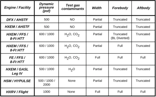
Support of the Hyper-X Program involves engine tests in several LaRC STF’s.57,58 These tests will provide means for direct comparison between ground tests and flight of engine flowpath models of the same scale as the flight vehicle engine. An artist’s concept of the Hyper-X Research Vehicle in flight is shown in Figure 24. In tests in the 8-Ft. HTT, the actual flight engine (FE) will be tested as schematically illustrated in Figure 25. The first series of ground tests at Mach 7 flight simulation will include various test hardware and facilities58 as indicated in Table 3, which includes some information about the flight simulation dynamic pressure, facility test gas quality, and geometric simulation of the model and test hardware. Results from the ground tests are expected to provide confirmation of the scramjet design methodology that grew from the extensive NASP data base and a direct comparison of test facility effects on flowpath performance of identical engine models.
The Hyper-X Engine Model (HXEM) will be tested in the 8-Ft. HTT, the AHSTF, and the GASL Leg-IV at Mach 7 flight conditions; the HYPULSE Scramjet Model (HSM) will be tested in HYPULSE at Mach 7 and 10 conditions; and the flight engine will be tested in the 8-Ft. HTT at Mach 7 conditions. All of these tests will use the full flowpath simulator (FFS) hardware with the same propulsive flowpath lines and of the same scale as the flight research vehicle, although some models will be of partial width. Data from these tests (and flight) will enable direct comparisons of facility effects and flight with the scramjet flowpath design methods.
Combined Cycle Engines
The capability to test combined cycle engine components was added to the DCSCTF, including systems capabile of delivering 2400 psig hydrogen and oxygen, silane, and high pressure water.
Some research in the area of rocket-based combined cycle (RBCC) airbreathing engine concepts is of interest because of the similarity to the long-standing nature of LaRC scramjet flowpath research activities. Tests of an RBCC model were recently completed and a preliminary report59 illustrates some of the direct-connect results at conditions simulating Mach 4 and 6.5 flight. In addition, some tests were made in a static mode to investigate ejector operation and with the model operated as a high area-ratio rocket for simulation of final ascent to orbit.Once the rocket was ignited and the combustion chamber pressure established, the air flow was reduced to zero to simulate high altitude operation to determine the thrust produced by the high area-ratio model. Data from the tests are currently being analyzed.
Concluding Remarks
A review of the Langley Research Center (LaRC) experimental research in supersonic combustion related to hypersonic airbreathing propulsion has been presented with emphasis on scramjet related research since 1987. This review covered the scramjet engine ground test effort in support of the National Aero-Space Plane (NASP) program and the current application to the Hyper-X flight demonstration program. From 1987 through
January 1998, a total of 2482 tests of 15 scramjet engine models have been conducted in LaRC scramjet test facilities at conditions simulating flight from Mach 4 to 8. In addition, investigations of scramjet components have been conducted which include studies of fuel mixing enhancement, fuel injection parallel to the combustor flow from the base of ramps, and nozzle operation.
Through the use of pulse facilities, such as shock-expansion tunnels, the ground test envelope has been extended into the hypervelocity regime to provide ground test capabilities simulating the combustor inflow conditions at up to Mach 17 flight speeds. Because of their short (several millisecond) test times, these facilities also have enabled the use of visualization and diagnostics of the combustor internal flow.
The major outcomes from the LaRC supersonic combustion and scramjet testing experience are the flowpath design methodologies, ground test techniques and capabilities, a scramjet test complex that spans the trans-atmospheric scramjet flight envelope, and tools for data analysis and interpretation. All of these provide the basis for scramjet design and performance assessment.
References
1. Andrews, E. H., Jr.; and Mackley, E. A.: NASA’s Hypersonic Research Engine Project—A Review. NASA TM-107759, October 1994.
2. Andrews, E. H., Jr.; and Mackley, E. A.: Review of NASA’s Hypersonic Research Engine Project. AIAA Paper 93-2323, June 1993.
3. Henry, J. R.; and Anderson, G. Y.: Design Considerations for the Airframe-Integrated Scramjet. NASA TM-2895, 1973.
4. Northam, G. B.; and Anderson, G. Y.: Supersonic Combustion Ramjet Research at Langley. AIAA Paper 86-0159, January 1986.
5. Northam, G. B.; Capriotti, D. P.; Byington, C. S.; Greenberg, I.: Mach 2 and Mach 3 Mixing and Combustion in Scramjets. AIAA Paper No. 91-2394, June 1991.
6. Anderson, G. Y.: An Outlook on Hypersonic Flight. AIAA Paper 87-2074, June 1987.
7. Thomas, S. R.; and Guy, R. W.: Scramjet Testing From Mach 4 to 20 Present Capability and Needs for the Nineties. AIAA Paper 90-1388, June 1990. 8. Rausch, V.L.; McClinton, C. R.; and Hicks, J. W.:
Scramjets Breathe New Life into Hypersonics. Aerospace America, July 1997, pp40-46.
9. Curran, E. T.: Scramjet Engines: The First Forty Years. ISABE Paper 97-7005, Sept. 1997.
10. Guy, R. W.; Rogers, R. C.; Puster, R. L.: Rock, K. E.; and Diskin, G. S.: The NASA Langley Scramjet Test Complex. AIAA Paper 96-3243, July 1996. 11. Henry, John R.: Fuel Injection and Mixing in
Scramjet Combustors. NASA TM X-1437, 1967. 12. Diskin, G.S.; and Northam, G. B.: Effects of Scale
on Supersonic Combustor Performance. AIAA Paper 87-2164, June 1987.
13. Byington, C. S.; Northam, G. B.; and Capriotti, D. P.: Transpiration Cooling in the Locality of a Transverse Fuel Jet for Supersonic Combustors. AIAA Paper 90-2341, July 1990.
14. Northam, G. B.; Greenberg, I.; and Byington, C. S.: Evaluation of Parallel Injector Configurations for Supersonic Combustion. AIAA Paper 89-2525, July 1989.
15. Capriotti, D. P.; Northam, G. B.; Greenberg, I.; and Byington, C. S.: Evaluation of Parallel Injector Configurations for Mach 3 Combustor Conditions.
Presented at the 26th JANNAF Combustion Meeting, Oct. 23-27, 1989, Pasadena, California. 16. Northam, G. B.; Greenberg, I.; Byington, C. S.; and
Capriotti, D. P.: Evaluation of Parallel Injector Configurations for Mach 2 Combustion. Journal of Propulsion and Power, Vol. 8, No. 2, March-April 1992, pp. 491-499.
17. Stouffer, S. D.; Baker, N. R.; Capriotti, D. P.; and Northam, G. B.: Effects of Compression and Expansion Ramp Fuel Injector Configurations on Scramjet Combustion and Heat Transfer. AIAA Paper 93-0609, January 1993
18. Northam, G. B.; Lempert, W. A.; Diskin, G. S.; and Gregory, R. W.: Supersonic Combustion Performance of Hydrogen/Hydrocarbon Mixtures as Determined by a Nonintrusive Temperature Monitor. AIAA Paper 88-3293, July 1988.
19. Jarrett, O., Jr.; Smith, M.W.; Antcliff, R.R.; Northam, G. B.; Cutler, A. D.; Capriotti, D. P.; and Taylor, D. J.: CARS Temperature Measurements in a Hypersonic Propulsion Test Facility. Presented at the 27th JANNAF Combustion Meeting, November 5-9, 1990, Cheyenne, Wyoming.
20. Smith, M.; Antcliff, R.; Cutler, A.; Jarrett, O.; and Northam, G.: CARS Temperature Measurements in a Hydrogen-Fueled Supersonic Combustor. AIAA Paper 90-5260, October 1990.
21. Baker, N. R.; Northam, G. B.; Capriotti, D. P.; and Stouffer, S. D.: The Effect of Entrance Radius and Film Injection on Wall Heating in Scramjet Nozzles. Presented at the 29th JANNAF Combustion Subcommittee Meeting, October 19-23, 1992, Hampton, Virginia.
22. Baker, N. R.; Northam, G. B.; Stouffer, S. D.; and Capriotti, D. P.: Evaluation of Scramjet Nozzle Configurations and Film Cooling for Reduction of Wall Heating. AIAA Paper No. 93-0744, Jan. 1993. 23. Tamagno, Jose; Bakos, Robert; Pulsonetti, Maria;
and Erdos, John: Hypervelocity Real Gas Capabilities of GASL’s Expansion Tube (HYPULSE) Facility. AIAA Paper 90-1390, June 1990.
24. Bakos, R. J.; Tamagno, J.; Rizkalla, M. V.; Pulsonetti, M. V.; Chinitz, W.; and Erdos, J. I.: Hypersonic Mixing and Combustion Studies in the GASL HYPULSE Facility. AIAA Paper 90-2095, July 1990.
25. Calleja, John; and Tamagno, Jose: Calibration of HYPULSE for Hypervelocity Air Flows Corresponding to Flight Mach Numbers 13.5, 15, and 17. NASA CR 191578, December 1993.
26. Thomas, S. R.; and Guy, R. W.: Expanded Operational Capabilities of the Langley Mach 7 Scramjet Test Facility. NASA TP 2186, Oct. 1983. 27. Andrews, E. A., Jr.; Torrence, M. G.; Anderson, G.
Y.; Northam, G. B.; and Mackley, E. A.: Langley Mach 4 Scramjet Test Facility. NASA TM-86277, 1985.
28. Reubush, D. E.; Puster, R. L.; and Kelly, H. N.: Modification to the Langley 8-Foot High Temperature Tunnel for Hypersonic Propulsion Testing. AIAA Paper 87-1887, June 1987.
29. Huebner, L. D.; Rock, K. E.; Voland, R. T.; and Weiting, A. R.: Calibration of the Langley 8-Foot High Temperature Tunnel for Hypersonic Propulsion Testing. AIAA Paper 96-2197, June 1996.
30. Erdos, J.; Calleja, J.; and Tamagno, J.: Increase in the Hypervelocity Test Envelope of the HYPULSE Shock-Expansion Tube. AIAA Paper 94-2524, June 1994.
31. Bakos, R. J.; Castrogiovanni, A.; Calleja, J. F.; Nucci, L.; and Erdos, J. I.: Expansion of the Scramjet Ground Test Envelope of the HYPULSE Facility. AIAA Paper 96-4506, November 1996. 32. Erdos, John I.; Bakos, Robert J.; Castrogiovanni,
Anthony; and Rogers, R. Clayton: Dual Mode Shock-Expansion/Reflected-Shock Tunnel. AIAA Paper 97-0560, January 1997.
33. Roffe, G.; Bakos, R.; Erdos, J.; Swartwout, W.: The Propulsion Test Complex at GASL. ISABE Paper 97-7096, Sept 1997.
34. Voland, R. T.; and Rock, K. E.: NASP Concept Demonstrator Engine and Subscale Parametric Engine Tests. AIAA Paper 95-6055, April 1995. 35. Beach, H. L.; Mackley, E. A.; Rogers, R. C.; and
Chinitz, W.: Use of Silane in Scramjet Research.
Presented at the 17th JANNAF Combustion
Meeting, September 1980. (CPIA Publication 329,vol. I, pp. 639-660, September 1980.)
36. Bement, D. A.; Thompson, M. W.; and Stevens, J. R.: Performance Evaluation of Semi-Freejet Tests of the Generic High Speed Engine. AIAA Paper 91-2163, June 1991.
37. Anderson, G.; Kumar, A.; and Erdos, J.: Progress in Hypersonic Combustion Technology with Computation and Experiment. AIAA Paper 90-5254, October 1990.
38. Ruf, Edward G.; and Young, Julie A.:NASA-Langley Parametric Scramjet Engine Tests, Vol.
I.-Overall Test Plan and Inlet Series Results. NASA CR-201702, July 1997.
39. Albertson, C. W.; and Andrews, E. H., Jr.: Mach 4 Tests of a Hydrocarbon-Fueled Scramjet Engine. 1995 JANNAF Airbreathing Propulsion Subcommittee Meeting, CPIA Pub. 639, Vol.2, pp. 17-34, December 1995.
40. Northam, G. B.; McClinton, C. R.; Wagner, T.C.; and O’Brien, W. F.: Development and Evaluation of a Plasma Jet Flameholder for Scramjets. AIAA Paper 84-1408, June 1984.
41. Wagner, T. C.; O’Brien, W. F.; Northam, G. B.; and Eggers, J. M.: Plasma Torch Ignition for Scramjets. AIAA J. of Prop. and Power, Vol. 5, No. 5, Sept-Oct 1989, pp. 548-554.
42. Vitt, Paul; Ferlemann, Paul; and Bobskill, Glenn: Description of the HSC-IPT Data Analysis Methodology. HNAG Memo 94-1-018, NASA Contract NAS1-19864, December 1994.
43. Rogers, R. C.; Weidner, E. H.; and Bittner, R. D.: Quantification of Scramjet Mixing in Hypervelocity Flow of a Pulse Facility. AIAA Paper 94-2518, June 1994.
44. Wang, L.-g; et al: Water Vapor Measurements for Combustion Diagnostics Using a 1350nm Tunable Diode laser. Presented at SPIE’s OE/LASE ’94, Jan 22-29, 1994, Los Angeles, CA.
45. Cutler, A. D.; Levey, B. S.; and Kraus, D. K.: An Experimental Investigation of Supersonic Swirling Jets. AIAA Paper 93-2922, July, 1993.
46. Kraus, D. K.; and Cutler, A. D.: Mixing
Enhancement by Use of Swirling Jets. AIAA Paper 93-3126, July 1993.
47. Cutler, A.; and Johnson, C.: The Use of Swirling Jet Pairs to Provide Rapid Fuel Penetration in Supersonic Combustors. AIAA Paper 95-0099, January 1995.
48. Fischer, K.; and Rock, K.: Calculated Effects of Nitric Oxide Flow Contamination on Scramjet Performance. AIAA Paper 95-2524, July 1995. 49. Rogers, R. C.: Effects of Test Facility Contaminants
on Supersonic Hydrogen-Air Diffusion Flames. CPIA Publication 457,Vol.1, pp.337-390, Oct. 1986. 50. Pellett, G. L.; Northam, G. B.; and Wilson, L. G.:
Strain-Induced Extinction of Hydrogen-Air Counterflow Diffusion Flames: Effects of Steam, CO2, N2, and O2 Additives to Air. AIAA Paper 92-0877, January 1992.
51. Tsai, C.-Y; Calleja, J. F.; Bakos, R. J.; and Rogers, R. C.: A Technique for Mixing Measurement in Hypervelocity Pulse Facilities Using Particle Scattering Imagery. AIAA Paper 96-2222, June 1996
52. Tsai, C.-Y.: A Two-Line Absorption Instrument for Scramjet Temperature and Water Vapor Concentration Measurement in HYPULSE. NASA CR-1998-207664. May 1998.
53. Smith, .W.; et al: Coherent Anti-Stokes Raman Spectroscopy Temperature Measurements in a Hydrogen Fueled Supersonic Combustor. AIAA J of Prop and Power, Vol. 9, No. 2, March-April 1993, pp.163-168.
54. Shirinzadeh, B; and Gregory, R. W.: Resonance lamp absorption technique for simultaneous determination of the OH concentration and temperature at 10 spatial positions in combustion environments. SPIE Proceed., Vol. 2122, Jan. 1994.
55. Diskin, G. S.; Lempert, W. R.; and Miles, R. B.: Observation of Vibrational Relaxation Dynamics in
X3Σg- Oxygen Following Stimulated Raman
Excitation of the v-1 Level: Implications for the RELIEF Flow Tagging Technique. AIAA Paper 96-0301, Jan. 1996.
56. Smith, M. W.; and Northam, G. B.: Application of Absorption Filter-Planar Doppler Velocimetry to Sonic and Supersonic Jets. AIAA Paper 95-0299, January 1995.
57. McClinton, C.R.; et al: Hyper-X Wind Tunnel Program. AIAA Paper 98-0553, January 1998.
58. Voland, R. T.; et al.: Hyper-X Engine Design and
Ground Test Program. AIAA Paper 98-1532, April, 1998
59. Nelson, K. W.; and Hawk, C. W.: Experimental Investigation of a Rocket Based Combined Cycle (RBCC) Engine in a Direct-Connect Test Facility.
JANNAF 34th Subcommittee Joint Meetings, W.
Palm Beach, FL, October 1997.
WG/T/ET032598
Program Engine CHSTF AHSTF 8' HTT Tests Total tests Time period
NASA NASP NASA Three-strut 178 90 0 268 Parametric 238 212 0 450 963 Pre-NASP (1976 - 1987) Step-strut 245 0 0 245 114 0 0 114 0 69 0 69 0 55 0 55 177 144 0 321 1223 Pre-TeamNASP (1987 - 1990) 0 72 0 72 31 202 0 233 359 0 0 359 0 160 0 160 0 142 0 142 326 (1990 - 1994)NASP-Team 0 0 24 24 Govt baseline Rocketdyne A Rocketdyne A1 Rocketdyne A2 Rocketdyne HC Rocketdyne A2+ Pratt & Whitney C
JHU/APL B1 NASP SX-20 NASP SXPE NASP CDE Parametric 400 0 0 400 683 132 0 0 132 Post-NASP (1994 - 1996) Hyper-X 1996 - 98 SXPE 0 124 0 124 CDE 0 0 27 27 DFX* 0 250 0 250 250 1874 * thru 1/98 1520 51 3445 3445
Table 1.- Airframe-integrated scramjet tests in the NASA Langley scramjet engine test facilities (Mach 4 to 8).
Engine / Facility
Dynamic pressure (psf)
Test gas
contaminants Width Forebody Aftbody
DFX / AHSTF HXEM / AHSTF HXEM / FFS / 8-Ft HTT HXEM / FFS / 8-Ft HTT FE / FFS / 8-Ft HTT HXEM / GASL Leg IV HXRV / Flight 500 500 600 / 1000 600 / 1000 600 / 1000 500 / 1000 1000 Partial Partial Partial Partial Full Partial Full Truncated Truncated Truncated (BL Diverted) Full Full Truncated Full Truncated Truncated Truncated Truncated Full Truncated Full NO NO H2O, H2O HSM / HYPULSE 500 / 1000 / 2000
Partial Truncated Truncated None
None CO2 H2O, CO2
M7HypXetm
Table 3.- Mach 7 Hyper-X engine test matrix.
H2O, CO2 Facility Primary use Flow energizing method (Max Tt, ∞ (°R)) Simulated flight Mach No.* Nozzle exit Mach No. Nozzle exit size (in.) Test section dimensions (ft) Direct-Connect Supersonic Combustion Test Facility (DCSCTF) Combustion-Heated Scramjet Test Facility (CHSTF) Arc-Heated Scramjet Test Facility (AHSTF) 8-ft High Temperature Tunnel (8' HTT)
*Based on stagnation enthalpy
Engine tests Engine tests Engine tests Combustor tests Combustor tests H2/O2/Air combustion (3800) H2/O2/Air combustion (3000) Linde (N=3) Arc Heater (5200) CH4/O2/Air combustion (3560) Shock-Expansion (15 550) 3.5 to 5.0 4.7 to 6.0 4.7 to 5.5 6.0 to 8.0 4.0 5.0 6.8 4.0 to 7.5 ---12.0 14.0 15.0 17.0 3.5 4.7 2.0 2.7 4.7 6.0 1.52 x 3.46 1.50 x 6.69 13.26 x 13.26 4 dia x 11 L 96 diameter 8 dia x 12 L (26 dia chamber) 4 dia x 30 L 11.17 x 11.17 10.89 x 10.89 Engine tests Reflected shock (7400) 7 10 7.2 6.4 7 dia x 20 L 26.25 diameter 4.0 5.0 6.8 2.5 W x 3.5 H x 8 L 4.7 4.8 or 6.2 5.0 7.2 6 dia 6 or 12 6 6 WG/T/EFac Hypersonic Pulse facility (HYPULSE) SETb RST/SETn
and altitude simulation
1960
'70
'80
'90
2000
Fuel injection, mixing
SAM in 8-Ft HTT Airframe Integrated Scramjet Concept AIM at LeRC AHSTF on line CHSTF online Three Strut AHSTF upgrade Parametric Step-strut HYPULSE on line HYPULSE upgrade 8-Ft. HTT O2 upgrade NASP Pre-team SX20 CDE SXPE DFX Parametric Component tests
Direct connect combustor
Injector combustor tests
Mixing recipes
Fuel ignition flameholding
Engine tests Nonintrusive diagnostics
Hypervelocity combustion
Computational methods Propulsion-airframe integration
Combustor design methods Engine tests continue
Hypersonic Research Engine
Scramjet Base Research National Aero
Space Plane CR/WGtimeline03259 DC050798.3 Scramjet design recipe DCSCTF online Parametric Hyper-X
Combined cycle concepts Flight demonstration
~
Figure 1.- Supersonic combustion research history at LaRC.
Thrust
Mach 4
Fuel flow a).- Three-strut engine.
b).- Strutless parametric engine.
c).- Step-strut engine.
Vehicle drag
Vehicle drag
Mach 7
Combustion Heated STF
M∞ = 3.5 - 6, Tt, max = 1700K
Direct-Connect Supersonic Combustion Test Facility
M∞ = 4 - 7.5, Tt, max = 2100K
Hypersonic Pulse Facility
M∞ = 12 - 19 (SET), T
t, max = 9000K M∞ = 7 - 10 (RST), T
t, max = 4200K
8 -Ft High Temperature Tunnel
M∞ = 4 - 7, Tt, max = 2000K Arc Heated STF
M∞ = 4.7 - 8, Tt, max = 2850K
Air
O2
H2 Vitiated air heater
Water-cooled supersonic nozzle Water-cooled supersonic nozzle
Mixer Water 10' Exhaust Combustor model Intake fan Intake tower To vacuum sphere To atmosphere DCSCTF.91/96 hypnozz Intake fan Intake tower Air O2 H2 Mach 3.5 & 4.7 nozzles Heater duct with heat sink liner with heat sink liner
Test cabin Air ejector H.P. Air supply Exhaust To vacuum sphere To atmosphere Vacuum ducting CHSTF new 1 Inside
building Outside 100 ft dia Vacuum sphere 10 Isolation valve Aftercooler Diffuser Dimensions in feet Test section Nozzle Arc heater plenum chamber 4 0 7.5 12 23 56.5 81 94 RV/EA010495.P4(TC) Methane O2 H2 Air storage Nozzle Test cabin Propulsion model Diffuser Combustor To vent stack Air ejector Silane RV/EA010495.P1(TR) Vacuum ducting Detonation or conventional driver Dual mode RST/SET 84" Test section and model mount
PLC control system 200-Channel D/A support Optical diagnostics
50 0 5 100 150 10 Flight Mach number
Altitude, (kft) 8-Ft.HTT
DCSCTF CHSTF
AHSTF
Figure 5.- Scramjet test facility operational envelopes.
50 0 5 100 150 200 250 300 350 400 10 15 20 25 30 0.5 1 2 4 6 8 10 12 14 1 10 10 2 103 104 105 106 107 108 109
Flight Mach number
Altitude, (kft)
1010
CR4798M
Stagnation pressure, psia
Defined operation conditions Stagnation enthalpy/1000, Btu/lbm
q∞, psf 200 600 2000 HYPULSE-RST HYPULSE-SET Enlarged section Shock tube Nozzle
Quick-operating clamping mechanisms Windows
Tractor wheels Variable position
model support
CR4798ST
Figure 6.- Hypulse RST/SETn for scramjet engine testing.
CR4798as
Heat loss
Isolator shock train
Fuel injection stages
Nozzle Combustor Isolator Inlet Shock boundary layer interactions Flow Drag Thrust Propulsion-airframe integrated scramjet
Forebody
compression Aftbody
expansion
Vehicle bow-shock
Figure 7.- Typical mid-speed airframe-integrated scramjet operation.
Figure 9.- Typical scramjet engine model installed in the CHSTF.
Forebody precompression
Boundary layer ingestion M1 M∞
Ht, ∞= f(M∞,alt.)
Facility nozzle boundary layer bypass
Forebody boundary layer ingestion Heater
b) Simulation in ground facility a) Flight Ht, ∞ M1 CR4798fs Engine module Aftbody nozzle Engine module
Figure 8.- Ground test simulation of flight conditions.
Facility nozzle exit
∆F F F
Fuel equivalence ratio
F
∆F
∆F
∆F
∆F = Fuel-on minus fuel-off engine axial thrust
Unstart, hydrogen Unstart, ethylene (piloted) Fuel Ethylene Hydrogen
Unfilled: Fuel only
Filled: Pyrophoric gas only Half filled: Fuel & Pyrophoric gas
WG4798
Figure 11.- Maximum performance with hydrogen and ethylene fuels in the CHSTF tests.
3.46 in. 1.8 in. Injector block Fuel injectors Plasma torch 48 in. Side view To ejector 2°
Figure 13.- VPI plasma torch design. Figure 10.- CDE and SXPE simulations compared to flight.
1.50 30° A A-A A Tangential gas inlet O-ring Plenum pressure Thermocouple (torch temp) Anode Ceramic O-ring groove 0.64 dia Copper tube
0.38 dia Stainless tube Ceramic insulator Cathode Lava sealant Conax fitting 0.40 1.0 Dimensions in inches 1.40 CR41298.4 NASP X-30 SXPE CDE M2, X-30 M1=6.8 M1=6.2 8-Ft. HTT AHSTF CH4+Air+O2 Flight Geometric scale 100% Geometric scale 30% Geometric scale 12.5% M2, CDE = M2, X-30 M∞=7 q∞ ~ 2000psf Re 1.9x10⁶/ft ~ ∞~~ M2, SXPE = M2, X-30 Re 1.1x10∞~~ 6/ft M∞=7 Enthalpy q∞ ~ 1200psf~ Air + NO Re 0.32x10∞~~ 6/ft M∞=7 Enthalpy q∞ ~ 500psf~ Typical SSTO trajectory Cowl Body Body Cowl Body Cowl RV/KRcdensxpe .5 1.0 1.5 Normalized pressure 2.0 2.5 0 1.89 x 10⁴ Q sccm Ar/H2α P Watts P/Q Watts/sccm 20% SiH4-H2 (1.50 x 10⁻⁴ kg/s) 20% SiH4-H2 (1.04 x 10⁻³ kg/s) NO FUEL 1.0 1536 0.081 10 20 30 40 50 60 φ t = 0.31 T t = 990K
Swept ramp injectors Unswept ramp injectors
1.51"
3.46" 0.6" 5.5"
Mach 3 shock wave diagram
Top view
End view Mach 2 shock wave diagram
o 80 o 40.0 o 10.3 o 39.6 M = 2 0.5" M = 3 o 22.0 o 10.3 o 27.7 o 3 o 3 a) Injector blocks
b) Mach 2 and 3 configurations
Figure 15.- Parallel ramp injector geometry schematic.
DC499814 1.00 0.80 0.60 0.40 0.20 0 0.20 0.40 0.60 0.80 1.00 1.20 1.40 1.60 1.80 Equivalence ratio Combustion efficiency Combustion efficiency A.- Perpendicular injection B.-Parallel injection Tt = 2500R Unswept Swept Tt = 3000R Tt = 3500R Tt = 2500 to 3700R DC4981c
}
1.00 0.80 0.60 0.40 0.20 0 0.20 0.40 0.60 0.80 1.00 1.20 1.40 1.60 1.80 Tt = 2500R Swept Unswept Tt = 3000R Tt = 3500R DC4982cFigure 17.- Performance of swept and unswept ramps for Mach 3.
Flow Flow
Compression Expansion
DCBNC98
Figure 18.- Compression and expansion ramp injectors.
4.3° G/2
X/G = 0
X/G = 0.9
G (Gap length) = 3 in.
X/G = 16 DC413982 A.- Perpendicular injection B.-Parallel injection
1.00 0.8 0.6 0.4 0.2 0 0.6 0.8 1 1.2 1.4 1.6 Equivalence ratio Combustion efficiency X/G= 3 Tt = 1940K P1 =1 atm Tt = 1940K P1 =1 atm X/G= 6 X/G= 12 DC41598a a) Compression ramp
Figure 20.- Combustion performance of ramp injectors. 1.00 0.8 0.6 0.4 0.2 0 0.6 0.8 1 1.2 1.4 1.6 Equivalence ratio Combustion efficiency DC41598b X/G= 3 X/G= 6 X/G= 12 b) Expansion ramp 1.00 0.8 0.6 0.4 0.2 0 0.1 0.2 0.3 0.4 0.5 Film equivalence ratio
Relative integrated heat flux
R/H = 1 R/H = 2 R/H = 0 DC050798.1 Nozzle throat Nozzle duct
7 in. Expansion plate (R/H = 0, 1, 2) 4 in. Plate
R
H
7 in. Plate
4 in. Injector block
11 in. Plate
DCCR416c