Pipeline
Standard
and
Construction
Specifications
Note: This technical standard has been developed by the Ohio Department of Natural Resources,
Division of Soil and Water Resources in order to recommend what is considered best practice for the protection of soil, water and related resources during pipeline construction. These are not to be
considered as mandatory requirements unless cited by other laws, rules or legal agreements. Users
are encouraged to use them as guidance for development of plans, on‐site practices and
implementation or for remediating problem areas.
I.
Description
A line of pipe with valves, pumps, and control devices used for the conveying of liquids, gases, or finely divided solids. Pipelines convey oil, gasoline, gas, water, or any other liquefied product. This
specification provides measures intended to limit the impact of the pipeline construction on agricultural productivity or on other lands where maintaining the natural soil and drainage attributes is important.
II.
Condition
Where
Practice
Applies
This practice applies where it is desirable or necessary to convey liquid or gaseous products in a closed conduit from one point to another point.
III. Definition
of
Terms
Agricultural Land ‐ Land which is presently under cultivation; land which has been previously cultivated and not subsequently developed for non‐agricultural use; and cleared land which is capable of being cultivated. It includes land used for cropland, hayland, improved pastureland, managed woodlands, truck gardens, farmsteads, commercial agricultural related facilities, feedlots, livestock confinement systems, land on which farm buildings are located, and land in government set‐aside programs. Best Management Practice ‐ Any structural, vegetative or managerial practice (BMP) used to treat, prevent or reduce soil erosion or to capture pollutants such as sediment. Such practices may include temporary seeding of exposed soils, construction of retention basins for storm water control and scheduling the implementation of all BMP’s to maximize their effectiveness. Cropland ‐ Land used for growing row crops, small grains, or hay; includes land that was formerly used as cropland but is currently in a government set‐aside program, and pasture land formerly used as cropland. Inspector – A person qualified by education and experience for the purpose of evaluating pipeline construction in relation to soils removal and replacement, drainage repairs, corridor restoration and other items identified in this standard. This person is sometimes retained by the pipeline company for the above purposes, but may be a third party that is mutually agreed upon by the landowner and the pipeline company. Landowner ‐ Person(s) holding legal title to property on the pipeline route from whom the pipeline company is seeking, or has obtained, a temporary or permanent easement.
Landowner’s Designate ‐ Any person(s) legally authorized by a landowner to make decisions regarding the mitigation or restoration of agricultural impacts to such landowner's property.
Page 2 of 22
ODNR‐DSWR
Pipeline Standard 12‐3‐13 Pipeline ‐ The pipeline and its related appurtenances. Pipeline Company ‐ The entity responsible for installing the pipeline, its successors, and assigns, on its own behalf and as operator of the company. Right‐of‐Way ‐ Includes the permanent and temporary easements that the pipeline company acquires for the purpose of constructing and operating the pipeline. Slope Breaker ‐ A ridge or channel constructed diagonally across a utility right‐of–way or a road (water bar) that is subject to erosion. Subsoil ‐ Subsoil is defined as the soil material that starts at the bottom of the topsoil to a depth of three feet. Exceptions to this are soils where fractured bedrock or hard bedrock is encountered before three feet.
Subsurface Drain or Drainage ‐ Any artificial system of pipes or conduits designed to intercept, collect, and convey excess soil moisture to a suitable outlet. These may include: clay and concrete tile, vitrified sewer tile, corrugated plastic tubing, and stone drains. Surface Drains ‐ Any surface drainage system such as shallow surface field drains, grassed waterways, open ditches, or any other conveyance of surface water. Tenant ‐ Any person lawfully residing on or in possession of the land. Topsoil ‐ The upper most part of the soil commonly referred to as the plow layer, the A layer, or the A horizon, or its equivalent in uncultivated soils. It is the surface layer of the soil that has the darkest color or the highest content of organic matter (as Identified in the USDA County Soil Survey and verified w/ right‐of‐way samples). Topsoil is described as all surface and near surface soil horizons (layers) that have a moist Munsell color value of 4 and chroma of 3 or darker and a clay content increase of 10% or less between the individual horizons. On agricultural land at least the top eight inches will be considered topsoil. Horizons with up to a twenty‐five percent mixing of the subsoil into the topsoil by agricultural processes will still be considered topsoil. In areas demonstrating substantial soil erosion, topsoil colors may be lighter than a moist Munsell color value of 4 and chroma 3. In these areas the top 8 inches will be considered topsoil. Surface horizons with a moist Munsell color value of 4 and chroma of 3 or darker in forested areas that have not been plowed are typically thinner. In these areas the top six inches will be considered topsoil. In areas where the above conditions do not apply, the top eight inches will be considered topsoil on agricultural land and the top six inches will be considered topsoil on forested land that has not been plowed.
Trench Breaker ‐ Trench breakers (also known as trench plugs) are barriers placed within an open pipeline excavation in order to slow flow and reduce erosion in the trench and also to prevent the trench from becoming a subsurface drainage path.
IV.
Planning
Phase
A. Construction Plans and Maps
The pipeline company shall provide the landowner general construction plan maps with the following information concerning agricultural areas/uses:
1. Pasture/Grazing areas including unimproved grazing areas (brushy or wooded land used by livestock), permanent open pasture (land devoted only to pasture use, not suited to tillage
rotation), improved pasture (including tillable rotation pasture/hayland), and livestock fence lines. 2. Cropland areas including hayland, rotation cropland, long‐term cropland and agricultural lands enrolled in either the annual set‐aside or the Conservation Reserve Program (CRP) of the U.S.D.A. Consolidated Farm Service Agency. Such lands will be identified through consultation with the offices of the Consolidated Farm Service Agency and the county Soil and Water Conservation District. 3. Unique Agricultural Lands, which include specialty cropland (vegetables, berries, etc.), orchards, vineyards, maple sugarbushes, organic mucklands, and permanent irrigation systems. The areas mentioned above will be identified with the help of the County Soil and Water Conservation Districts.
B. Sensitive Agricultural Soils
Sensitive agricultural soils are defined as areas of cropland, hayland, or pasture that are more susceptible than other agricultural soils to construction disturbance due to slope, relative soil wetness, and/or shallowness to bedrock. Wetness conditions are the result of factors such as landscape position, soil texture, seasonal water table and/or slowly permeable subsoil horizons (e.g., areas of laterally draining subsoils). All sensitive agricultural soils including, but not limited to, those identified in the county soil survey as fragipans, lacustrine soils, dense basal tills, soils with a seasonally high water table, or soils with less than 5 feet of depth to bedrock are to be located and identified on the project map using the following codes: 1. "SE" ‐ designates the general area of soils sensitive to erosion due to R‐O‐W factor(s) of slope and/or the texture of exposed soil. 2. "SW" ‐ designates the general area of soils susceptible to soil horizon wetness as described above. 3. "SR" ‐ designates the general area of soils susceptible to shallow depth to bedrock. 4. "SO" ‐ designates the location of unavoidable organic mucklands. C. Other Features In addition, the pipeline company shall note the following information on the general construction plan maps or on the construction alignment sheets. 1. Other land and water management features including subsurface drainage areas (where they can be identified prior to construction), open ditches, diversions, diversion terraces, buried utility lines (for farmstead consumptive use), water sources (developed springs, etc.), grassed waterways, water impoundment structures (dams and ponds) and unnamed water flows. 2. Depth of cover if it varies from those listed in the Construction Specifications. 3. Any off right‐of‐way access roads and work or storage areas. Map all such areas identified at the time of the construction plan submission, indicating their proposed locations. Any other areas that may be identified during construction will be considered and filed as a change in the construction plans. 4. The planned location of any compressor stations, valve stations, metering and regulating stations and any other proposed facilities including pipeline markers.
Page 4 of 22
ODNR‐DSWR
Pipeline Standard 12‐3‐13 5. Locations for best management practices for control of erosion, sediment and trench water. Plans should note relevant sizes, grade, capacities and materials of practices. Trench breakers and slope breakers (permanent and temporary) shall be provided on the plan and during construction. See Figure 11 through 13 for more information regarding trench and slope breakers. Plans shall include notations of the distance between breakers based on percent of slope, or appended charts of breaker spacing by percent of slope. 6. General locations for subsurface intercept drains to control soil saturation and/or aid trench breakers in minimizing water piping, based on the sensitive agricultural soils data (see Section B) and site monitoring. Such locations will generally coincide with "SE" sensitive agricultural soils and breaks in slopes.
D. Point of Contact during Construction
Prior to the construction of the pipeline, the pipeline company shall provide to each landowner, landowner’s designate and/or tenant: the name, telephone number and mailing address of the pipeline company representative assigned to that geographic area and responsible for the liaison activities on behalf of the pipeline company. This pipeline company representative shall be the contact person both during construction and operational related activities. The pipeline company shall respond promptly to any landowner and/or tenant issues or concerns both during construction and long‐term operational activities.
V.
Construction
Specifications
A. Ingress and Egress Routes
Prior to the pipeline installation, the pipeline company and the landowner shall reach a mutually acceptable agreement on the route that will be utilized for entering and leaving the pipeline right‐of‐ way, should access to the right‐of‐way not be practical or feasible from adjacent segments of the pipeline right‐of‐way or from public highway or railroad right‐of‐ways. Where access road access ramps/pads are required from the highway to the pipeline construction area, the topsoil shall be removed and stockpiled for replacement, an underlayment of durable geotextile matting shall be placed over the exposed subsoil surface prior to the placement of temporary rock access fill material (see earlier materials regarding access road entrances and Figure 1 below). All such material will be removed upon completion of the project. The use of durable geotextile matting as an underlayment helps prevent rock and stone from becoming embedded in the subsoil material. Complete removal of the ramp upon completion of the project and restoration of the impacted site is required prior to topsoil replacement. B. Temporary Roads The location of temporary roads to be used for construction purposes will be negotiated with the
be designed to not impede proper drainage and will be built to minimize soil erosion on or near the temporary roads. Every attempt will be made to use existing farm lanes for access and to repair damages to the existing lanes. Upon construction completion, temporary roads may be left intact through mutual agreement of the landowner, the tenant and the pipeline company unless otherwise restricted by federal, state or local regulations. If the temporary roads are to be removed, the right‐of‐way upon which the temporary roads are constructed will be returned to its previous use and restored to a condition equivalent to that existing prior to their construction.
C. Clearing of Brush and Trees in the Right‐of‐Way
Unless otherwise restricted by federal, state or local regulations, the pipeline company shall follow the landowner's desires as stated in the easement agreement regarding the disposal of trees, brush and stumps of no value to the landowner by burning, burial, chipping, etc., or complete removal from any affected property. The pipeline company shall identify black cherry trees located on the right‐of‐way near active livestock use areas during the construction plan development. Black cherry tree vegetation is toxic to livestock when wilted and shall not be stockpiled in areas accessible to livestock. During the clearing phase, such vegetation will be disposed of in a manner that prevents contact with livestock. Unless otherwise restricted by federal, state or local regulations, the pipeline company shall follow the landowner's or landowner designate’s desires as stated in the easement agreement regarding the removal of tree stumps that the pipeline company might otherwise leave in the ground.
D. Soil Removal and Protection
1. Topsoil and subsequent horizons shall be determined by a properly qualified inspector, soil scientist or soil technician who will set stakes or flags every 200 feet along the right‐of‐way identifying the depth of topsoil to be removed. Topsoil will be stripped to the actual depth of the topsoil, not to exceed 16 inches (see Figure 2 Depth of Topsoil Removal), along the construction right‐of‐way and other areas where construction activities warrant (e.g. staging areas), including land that is currently forested. Full right‐of‐way topsoil stripping will avoid issues such as topsoil mixing from deep rutting and topsoil compaction. Topsoil may not be intermixed with subsoil materials. Topsoil will be stored in a windrow parallel to the pipeline trench in such a manner that it will not become intermixed with subsoil materials. In forested areas where clearing activities are necessary, minimal amounts of topsoil mixing may occur. 2. Topsoil shall be removed following clearing and prior to any activity by any equipment or Note: Where the topsoil is finely textured and is deeper than 12 inches, stripping is required to the depth of the subsoil, or 16 inches, whichever is less.
d d s c t e s s F s s b t o m 3. A t w t I p c s p c s 4. T b p t 5. I s i a 6. R c p r t 7. R 8. T c d p 9. S delivery truck depths of top stockpiled alo construction the soil profil extent practic stockpiling wi slope edge of Figure 4). Wh separately sto side, suitable be provided o to ensure the of the topsoil material. All subsoil ma the trench wi windrow para that is separa f any soil hor profile has a s concentration separated in o pre‐existing c concentration section of the The soil below be placed in a pipeline trenc topsoil and su n backfilling t substratum m nto the trenc and topsoil. Refer to Item construction procedures p removal from topsoil. Refer to Item The topsoil m contour will b drainage ditc purpose or re Surface drain Page ks. During the psoil stripping ong either edg requires cut‐a e across grad cable, topsoil ill be located f the right‐of‐ here topsoil ca ored on the u right‐of‐way on the down s e complete se from all cut‐ aterial that is ll be placed in allel to the pip ate from the t rizon or sectio significant inc n of rock, that order to be p contours. In n n of rock be in e profile. w the subsoil a third windro ch that is sepa ubsoil windro the trench, th material will b ch before rep F of these specifications ertaining to r m the subsoil a O for proced must be replac be restored. T h, or other cr emoved from age should no e 6 of 22
ODNR e clearing/gra g. Topsoil shal ge and on the and‐fill of des, to the on the up way (see annot be up slope space will slope side egregation and‐fill removed fro n a second peline trench topsoil windro on of the soil crease in the t soil shall be laced back at o case shall t ncreased in a (substratum) ow parallel to arate from th ows. he stockpiled be placed bac lacing the sub s for rock and dures pertaini ced so that af The same sha rossings. In n the right of w ot be blocked R‐DSWR
Pipeline ding phase, t ll be removed e right‐of‐way m h ow. t he ny ) will o the he k bsoil ing to the alle fter settling o all apply wher o instance wi way. d or hindered Figure 4 Tops (NY State Dep Figure 3 Tops e Standard 12‐3 the inspector d from the fu y. (See Figure eviation of co occurs, the top re excavation ill the topsoil d in any way. I soil stockpiling pt. of Agricultu soil and other s
‐13 shall monito ll width of the e 3.) Where ri ompaction of psoil's origina ns are made f materials be If excess spoi g on slopes
ure & Markets soil segregatio r site‐specific e right‐of‐wa ght‐of‐way the topsoil. al depth and for road, strea e used for any l is produced s Pipeline Draw on. c y and am, y other , it will wings).
be removed offsite to prevent ridging. Adding additional spoil to the crown over the trench in excess of that required for settlement will not be permitted. E. Depth of Cover 1. Except for above‐ground piping appurtenances, such as mainline block valves, tap valves, meter stations, etc., and except as otherwise stated in the Agreement, the pipeline will be buried as follows: a) On cropland, pastureland or other agricultural land provide a minimum of 60 inches of cover. b) On wooded or brushy land that is not suitable for cropland provide a minimum of 36 inches of cover. c) A minimum of 60 inches of cover shall be maintained over the top of the pipeline where it crosses surface drains, diversions, grassed waterways, open ditches, and streams. 2. In those areas where rock in its natural formation is encountered, the minimum depth of cover will be 36 inches. 3. On agricultural land subject to erosion, the company is responsible for inspecting the pipeline right‐of‐way on a reasonably frequent basis in order to detect areas of erosion to the cover so that no cover will be less than 3 feet at any time. 4. A minimum of 12 inches of separation shall be maintained between the pipeline and drainage lines unless adequate measures are taken to protect the present and future integrity of the pipeline and the subsurface drain.
F. Rock Removal (Shallow Soils)
The cover within the pipeline trench, bore pits, or other excavations shall not be backfilled with soil containing rocks of any greater concentration or size than existed prior to the pipeline construction. The following rock removal procedures only pertain to rocks found in the topsoil, subsoil, and substratum.
A. Before replacing any topsoil, all rocks greater than 3 inches in any dimension will be removed from the surface of all exposed subsoil (i.e. work area and subsoil storage areas). All material placed above the pipe shall not contain rocks of any greater concentration or size than existed prior to the pipeline construction.
B. All rocks greater than 3 inches in any dimension will be removed from the topsoil surface using a rock rake following final restoration unless undisturbed areas adjacent to the ROW can be shown to contain similar concentration and size. C. If trenching, blasting, or boring operations are required through rocky terrain, suitable precautions will be taken to minimize the potential for oversized rocks to become interspersed with adjacent soil material. Landowners/operators and adjacent landowners will be given timely notice prior to blasting. D. Rocks and soil containing rocks removed from the subsoil areas, topsoil, or from any excavations will be returned to the pre‐existing soil horizon levels, hauled off the landowner's premises or disposed of on the landowner's premises at a location that is mutually acceptable to the landowner and the company and in accordance with any applicable laws or regulations.
Page 8 of 22
ODNR‐DSWR
Pipeline Standard 12‐3‐13 G. Repair of Damaged and Adversely Affected Subsurface Drains
All subsurface drainage repair and/or replacement shall be completed prior to topsoil replacement. If subsurface drainage is damaged by the pipeline installation, it shall be repaired in a manner that assures the drain's proper operating condition at the point of repair. If subsurface drain lines in the pipeline construction area are adversely affected by the pipeline construction, the pipeline company will take such actions as are necessary to insure the proper functioning of the drain lines, including the relocation, reconfiguration, and replacement of the existing drain lines. The following standards and policies shall apply to the drain line repair: 1. All effort shall be made to locate all subsurface drainage within the right‐of‐way prior to the pipeline installation. The pipeline company will contact the local County Soil and Water Conservation Districts and affected landowners/tenants for their knowledge of subsurface drain locations prior to the pipeline installation. All identified drain lines will be marked with a 4 foot stake to alert construction crews to the need for subsurface drain repairs. 2. During construction all drain lines that are damaged, cut, or removed shall be distinctly marked by placing a highly visible 4 foot stake in the trench spoil bank directly opposite each drain line. This marker shall not be removed until the drain line has been permanently repaired and such repairs have been approved and accepted by the landowner, or the landowner’s designate. Technical assistance may be available from the local County Soil and Water Conservation District. Repair shall follow guidelines set forth in this document and in Figures 5 through 10 regarding drainage repair. 3. All drain lines shall be repaired with materials of the same or better quality as that which was damaged. The repair plans shall be approved by the landowner, or the landowner’s designate. The repair may require the installation of a submain to reduce the number of drain lines crossing the pipeline (see Figure 10 drainage system new submain). 4. Where drain lines are severed by the pipeline trench, steel channel iron, steel angle iron, full‐ round slotted steel pipe, half‐round steel pipe, or schedule 80 PVC pipe with 1/8 inch diameter holes shall be used to support the drain lines across the trench (see Figures 5 through 10). (Schedule 80 PVC pipe shall be limited to lengths without joints.) a. If the drain repairs involve clay or concrete tile, the support member shall extend to the first tile joint beyond the minimum 3‐foot distance. If the drain repairs involve plastic pipe it shall be supported at a 90‐degree angle from the bottom of the drain. This may involve using angle Iron to provide proper support. b. There shall be a minimum of 12 inches of clearance between the drain line and the pipeline whether the pipeline passes over or under the line. If this clearance cannot be attained, the drain line must be protected from damage that might result from the proximity of the pipeline. c. In no instance shall the grade of the drain line be decreased. d. To prevent settlement of the drain repair, the trench, from the bottom of the pipeline to 1 foot above drain repair, shall be backfilled with coarse aggregate.
5. Before completing permanent drain repairs, all drain lines shall be examined by suitable means (see Figure 5 regarding drainage line inspection) on both sides of the trench for their entire length within the right‐of‐way to check for drain that might have been damaged by construction equipment. If any drain line is found to be damaged, it shall be repaired so it will function as well after construction as before construction began. 6. Temporary repairs of drain lines shall be made as soon as exposed. This shall include the use of filter material to prevent the movement of soil into the drain line or the temporary plugging of the drain line until permanent repairs can be made. 7. All permanent drain line repairs shall be made within 30 days following completion of the pipeline installation on any affected landowner's property. 8. Following completion of the pipeline construction, the pipeline company shall also be responsible for correcting and repairing all drain line repairs that fall on the permanent and construction right‐of‐way. The plans for the repairs shall be approved and accepted by the landowner, or the landowner’s designate. Technical assistance for plan or site review or may be available from the local County Soil and Water Conservation District. 9. The pipeline company shall also document the location and known elevations of all drain lines that are found and/or repaired and provide a photo or description of the repair. Documentation should include a map with the latitude and longitude of drain lines encountered and repaired. This information shall be provided to the local County Soil and Water Conservation District and made available to the landowner or the landowner’s designate.
Page 10 of 22
ODNR‐DSWR
Pipeline Standard 12‐3‐13
Notes: 1. Perforated pipe shall be installed so that holes are facing down. 2. The perforated rigid support pipe is shouldered back into the firm, undisturbed soil profile to ensure consistent gravity flow gradient of the drainage line across the trench as the backfill material gradually settles for up to two years. 3. Long stretches of the pipe support across the trench may need to be supported by sand bags or other means to prevent sagging.
Notes: 1. Exte sides 2. Prov 3. Shou reloc is to
Figure 7 Re nd support an s of trench, m vide steel sup uld a drain cro cated into un be installed t epair of severe nd replaceme measured perp port for drain oss a ditch at disturbed soi to match elev ed drainage lin ent drainage pendicular fro n tile or plasti a skew of gre l or out of co vation of exist nes. line a minimu om the wall o c pipe to mai eater than 45 nflict with th ting pipes.
um of 3 feet o of the trench. intain functio 5 degrees, the e pipeline dit onto undistur . on while the d e replacemen tch. The repla
rbed earth on ditch is open. nt drain is to b acement drai n both be in pipe
Notes: 1. Tren along 2. Inter distu cond 3. Agric
Figure 8 In ch breakers p g the pipeline rcept drains r urbed backfill ditions along t cultural cropl nterception of Page prevent gully e after backfil receive soil m soil within th the pipeline. and may requ f drainage cros 12 of 22
ODN erosion while lling. oisture drain he trench. Th uire cross tre ssing the pipeli
NR‐DSWR
Pipelin e the trench i ing naturally he intercept d nch drainage ine trench. ne Standard 12‐3 is open and h from the und drain lines hel e or parallel d 3‐13 help to inhibit disturbed soil lp prevent sa rainage. t water piping l profile into t turated soil g the
Note: Parallel drainage installation shall be approved for agricultural soil conditions where repair of existing cross drainage would be less effective. For example, in situations of: 1. Shallow bedrock. 2. Interference by other utility lines. 3. Closely spaced shallow drains and french drains where a header is needed. Figure 9 Interception of drainage crossing the pipeline trench.
Note consu Figure : To be deter ultation with 10 A new subm Page mined by an the local Soil main may be n 14 of 22
ODN agricultural s and Water C needed to allow NR‐DSWR
Pipelin pecialist base Conservation w continued fu ne Standard 12‐3 ed on slope a District. unction of dra 3‐13 nd drainage a ainage systems area in s.
Figure 11 Trench breakers reduce trench erosion and the volume and velocity of trench water at the bottom of the slope (figure from New York Department of Agriculture Pipeline standards).
Page 16 of 22
ODNR‐DSWR
Pipeline Standard 12‐3‐13
Trench
Breaker
(also
known
as
trench
plugs)
Spacing
(Adapted from the Pennsylvania State Standards) Slope (%) Spacing (feet) 0‐5 Not Required except at stream or water body crossings 5 ‐ 15 300 >15 – 30 200 >30 100
Slope (%) Spacing (feet) 5 ‐ 15 300 >15 – 30 200 >30 100 Notes: 1. Trench breakers are required at all stream, river, or water‐body crossings regardless of trench slope. 2. Depending on the specific conditions of slopes exceeding 40%, the spacing between trench breakers may continue diminishing as illustrated, or may cease once a spacing of 30 to 35 feet has been reached. 3. Trench breakers may be sand bags or earth filled sacks (not topsoil), which are durable yet flexible and will conform to gradual shifting of pipeline and backfill, while serving their function, to impede the flow of subsurface water along the trench. In some cases cement filled bags or mortared stone may be used. 4. In agricultural lands, the top of trench breaker will not be closer than two feet from the restored surface.
Figure 12 Trench breakers (also known as trench plugs) should be placed in the trench before crossing water bodies and spaced in the trench based on the percent slope.
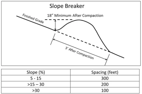
Figure 13 Slope breakers are similar to water bars and should be spaced based on the percent slope.
H. Slope Breakers Slope breakers are necessary to limit erosion on most rights of way, except in cultivated and residential areas. Slope breakers shall divert surface runoff to adjacent stable vegetated areas or to energy‐dissipating devices. Water shall be released in a non‐erosive manner. Generally, slope breakers are installed immediately downslope of all trench breakers. The gradient (fall) for each slope breaker shall be two to four percent unless otherwise approved by state inspectors based on site conditions. Slope breakers shall be installed as specified on the construction drawings or with a maximum spacing as shown in Figure 13.
I. Return to Pre‐construction Contours
Once disturbed areas are stabilized and within 2 years of completion of pipeline construction, slope breakers, water bars, diversions and other similar grade stabilization structures shall be graded to original pre‐construction contour elevations (unless negotiated to remain with the landowner). J. Construction Debris, Erosion, Sediment and Other Pollution Control Practices and Restoration of
Right‐of‐Way Best management practices shall be applied on pipeline projects in a timely manner to capture sediments and other pollutants, to prevent erosion and the release of pollution and to prevent degrading water resources. Practices applied, including slope breakers (Figure 13) shall meet the specifications and standards published by the Ohio Department of Natural Resources, Division of Oil and Gas Resources, the Division of Soil and Water Resources, the USDA Natural Resources Conservation Service (Field Office Technical Guide) or other applicable standards. All construction‐related debris and material, including litter generated by the construction crews will be removed from the right‐of‐way. Following the completion of the pipeline or any significant portion, the right‐of‐way will be restored to its original pre‐construction elevation and contour. If uneven settling occurs or surface drainage problems develop as a result of the pipeline construction, the pipeline company will provide land leveling services within 45 days of being notified by the landowner. Delays due to poor weather and soil conditions may be permitted.
K. Installations of Additional Drainage Lines
The pipeline company shall be responsible for installing such additional drain and other drainage measures as are necessary to properly drain wet areas on the permanent and temporary right‐of‐ ways caused by the construction and/or existence of the pipeline.
L. Repair of Damaged Soil Conservation Practices
All soil conservation practices (such as spring developments and pipelines, terraces, grassed waterways, water and sediment control basins, critical area seedings, etc.) damaged by the pipeline’s construction will be restored to their pre‐construction condition and approved by the landowner or local SWCD. For example, grassed waterways shall be graded to original dimensions and grades with erosion control matting installed.
Watering sources, such as spring developments, affected by pipeline construction, shall be replaced with an alternative supply of water within 24 hours of the watering source being disrupted unless the disruption has been negotiated with the landowner. An alternative supply of water shall be provided until the water source is fully functional at pre‐construction flow rates.
Page 18 of 22
ODNR‐DSWR
Pipeline Standard 12‐3‐13 M. Control of Trench Washouts, Water Piping and Blowouts
Trench breakers shall be installed for the dual purpose of preventing trench washouts during construction and abating water piping and blowouts subsequent to trench backfill. The distances between permanent trench breakers will be as described in plans and meet the spacing shown in Figure 12. Plans will record each installed trench breaker location, by map‐referenced station‐ number.
N. Pumping Of Water from Open Trenches
No back filling shall be done in water filled trenches. All freestanding water shall be removed prior to any back filling. In the event it becomes necessary to pump water from open trenches, the pipeline company shall pump the water in a manner that will avoid damaging adjacent agricultural land, crops, and/or pasture. Such damages include, but are not limited to: inundation of crops for more than 24 hours, sheet and rill erosion, discharge of sediment in ditches and other water courses, and the deposition of gravel in fields, pastures, and any water courses. If it is impossible to avoid water‐related damages as described above, the pipeline company will restore the land, pasture, watercourses, etc. to their pre‐construction condition. All pumping of water shall comply with existing drainage laws, local ordinances relating to such activities, and provisions of the Clean Water Act.
O. Compaction, Rutting, Fertilization, Liming, Seeding (Temporary and Permanent) and Mulching
1. In all agricultural sections of the right‐of‐way traversed by vehicles and construction equipment, where topsoil is stripped and prior to topsoil replacement, the subsoil shall be fractured by deep ripping to a depth of 16 inches below the surface of the subsoil with the appropriate industrial ripper. Note that some subsurface features (e.g. drain, other utilities) may warrant less depth. The ripper shall have maximum teeth spacing of 16 inches. The ripping shall be performed parallel to the pipeline and at 30 degrees to the pipeline. Following the ripping operation all stone and rock material three (3) inches and larger in size which has been lifted to the surface shall be collected and removed from the site for disposal. Upon approval by the inspector of the subsoil decompaction and the stone removal, the topsoil temporarily removed for the period of construction shall then be replaced. The soil profile in the full width of the right‐of‐way shall be shattered to a depth not to exceed 16 inches with a heavy‐ duty sub‐soiling tool having angled legs. Stone removal shall be completed, as necessary, to eliminate any additional rocks and stones brought to the surface as a result of the final subsoil shattering process.
2. The entire right‐of‐way will then be disked. Three passes will be made across any agricultural land that is ripped. 3. Ripping and disking will be done at a time when the soil is dry enough for normal tillage operations to occur on undisturbed farmland adjacent to the areas to be ripped. 4. All rutted and compacted land will be restored as near as practicable to its original condition. 5. All disturbed areas will be provided temporary and permanent vegetative cover as needed in order to prevent erosion and to re‐establish agreed upon vegetative cover.
trees, or shrubs) that have been agreed upon by the landowner shall be utilized. b. Seeding or planting shall be repeated if a satisfactory stand has not been obtained after
1 growing season.
c. Areas that reach final grade or are planned to be idle shall be seeded within 7 days of the most recent disturbance, or within 2 days within 50 feet of streams or water resources. Areas left idle during periods that are unsuitable for planting shall be provided appropriate cover using mulch or erosion control matting. Areas nearing or exceeding 3:1 slopes are candidates for use of rolled erosion control products (matting) or turf reinforcement matting if they are not cropped. d. All disturbed areas will be seeded and mulched according to guidance provided in the ODNR Rainwater and Land Development manual or USDA NRCS Standard Codes: i) 342 – Critical Area Planting, ii) 484 – Mulching, and iii) Appendix A Seeding Tables. In all areas where permanent vegetation is re‐established, the landowner will be consulted to select an appropriate weed‐free seed mixture or planting stock. Mulch should be held in place using tackifier or by crimping with a straight disk or other applicable implement, in order to prevent mulch from being removed by wind or runoff. 6. Depending upon the construction schedule and the landowner’s cropping plans, allowance may be made to allow the landowner to be appropriately compensated and to apply the appropriate type and amounts of fertilizer, manure, and/or lime in coordination with the landowner’s farming plans. In this case, an area may require temporary seeding and or mulch if an area is left idle for an extended number of days or weeks.
7. In Ohio, subsoil decompaction and topsoil replacement activities may have to be performed as weather permits due to the generally unsuitable weather for continuing agricultural land restoration in late autumn, winter, and early spring.
P. Backfill Profile and Trench Crowning
Material shall be used to backfill the trench in an order and manner that corresponds to the original profile, that is, substratum followed by subsoil and then topsoil. All rock not utilized as trench backfill material shall be removed from the right‐of‐way. The remaining backfill material shall consist of suitable subsoil material. Trench crowning shall occur during the trench backfilling operation using subsoil materials over the trench to allow for trench settling. In Ohio, this will be performed in accordance with Figure 14 below. In areas where trench settling occurs after topsoil spreading, imported topsoil shall be used to fill each depression. Topsoil from the adjacent agricultural land shall not be used to fill the depressions. Settlement inspections shall occur at 3 months, 1 year, 2 year and 3 years after construction has finished. In agricultural areas where the materials excavated during trenching are insufficient in quantity to meet backfill requirements, the soil of any agricultural land adjacent to the trench and construction zone shall not be used as either backfill or surface cover material. Under no circumstances shall any topsoil materials be used for pipe padding material or trench backfill. In situations where imported soil materials are employed for backfill on agricultural lands, such material shall be of similar texture and quality to the existing soils on site. Imported soils should be from similar soil types and free from noxious weeds and other pests to the extent possible.
Page 20 of 22
ODNR‐DSWR
Pipeline Standard 12‐3‐13 Q. Fencing All fencing and gates removed for the installation of the pipeline shall be replaced or installed according to the landowner’s specifications. Temporary fencing shall be provided as necessary to restrict access to active work areas by livestock until there is adequate vegetative cover over the work area. R. Pipeline Markers Unless specified by law, pipeline markers shall be located at roads, fence lines and edge of field boundaries where they will not be damaged or disrupt farming operations. S. Reinforced Crossings Unless declined by the landowner, the pipeline company shall provide at least one reinforced crossing for the purpose of logging access on woodlots that will be isolated from the rest of the parcel or from public roads by the pipeline.
Three
Year
Monitoring
and
Remediation
1. General Monitoring and Remediation A monitoring and remediation period shall be provided of no less than three years immediately following the full‐length activation of the pipeline or the completion of initial right‐of‐way restoration, whichever occurs last. The pipeline company shall be responsible for the cost of the monitoring and remediation. The three‐year period allows for the effects of climatic cycles such as frost action, precipitation and growing seasons to occur, from which various monitoring determinations can be made. The monitoring and remediation phase shall be used to identify any remaining impacts associated with the pipeline construction that are in need of correction and to implement the follow‐up restoration. General right‐of‐way conditions to be monitored include topsoil thickness, relative content of rock and large stones, trench settling, crop production, drainage and repair of severed fences, etc. The problems or concerns shall be identified through on‐site monitoring of all areas along the right‐of‐way and through contact with the respective landowner/operator and local County Soil and Water Conservation District. Topsoil deficiency and trench settling shall be restored with imported topsoil that is consistent with the quality of topsoil on the affected site. Excessive amounts of rock and oversized stone material shall be determined by a visual inspection of the right ‐of‐way. Results shall be compared to portions of the same field located outside of the right‐of‐way. Included in the determination of relative rock and large stone content is the right‐of‐way's condition subsequent to tillage and the relative concentration of such materials within the right‐of‐way as compared to off the right‐of‐way. All excess rocks and large stones shall be removed and disposed of by the pipeline company. On‐site monitoring shall be conducted at least three times during the growing season and shall include a comparison of growth and yield for crops on and off the right‐of‐way. When the subsequent crop productivity within the affected right‐of‐way is less than that of the adjacent unaffected agricultural land, the landowner, in conjunction with the pipeline company as well as other appropriate organizations, shall help to determine the appropriate rehabilitation measures for the pipeline company to implement. During the various stages of the project, all affected farm operators shall be periodically apprised of the duration of remediation by the pipeline company. Because conditions that require remediation may not be noticeable at or shortly after the completion of construction, the signing of a release form prior to the end of the remediation period shall not relieve the pipeline company's responsibility to fully redress all project impacts. After completion of the specific remediation period, the pipeline company shall continue to respond to the reasonable requests of the landowner/operators to correct project related effects on the agricultural resources. On lands subject to erosion, the pipeline company shall patrol the pipeline right‐of‐way with reasonable frequency to detect erosion of the top cover. Whenever the loss of cover due to erosion creates a pollution or safety issue the pipeline company shall take corrective action. 2. Specific Monitoring and Remediation After the moisture of the soil profile on the affected right‐of‐way has returned to equilibrium with the adjacent off right‐of‐way land, subsoil compaction will be tested using an appropriate soil penetrometer or other soil compaction‐measuring device. Compaction tests shall be made for each soil type identified on the affected agricultural land. The subsoil compaction test results within the right‐of‐way shall be compared with those of the adjacent off right‐of‐way portion of the affected farm field/soil unit. Where representative subsoil density on the right‐of‐way exceeds the representative subsoil density outside
Page 22 of 22