Technical Report
PKT-TR-ARCH-V01-991201
Notice
This PacketCable technical report is a cooperative effort undertaken at the direction of Cable Television Laboratories, Inc. (CableLabs®) for the benefit of the cable industry. Neither CableLabs, nor any other entity participating in the creation of this document, is responsible for any liability of any nature whatsoever resulting from or arising out of use or reliance upon this document by any party. This document is furnished on an AS-IS basis and neither CableLabs, nor other participating entity, provides any representation or warranty, express or implied, regarding its accuracy, completeness, or fitness for a particular purpose.
Copyright 1999 Cable Television Laboratories, Inc. All rights reserved.
Abstract
This technical report describes the architecture framework for PacketCable networks including all major system components and network interfaces necessary for delivery of PacketCableservices. The intended audience for this document includes developers of equipment intended to be conformant to PacketCablespecifications, and network architects who need to understand the overall PacketCablearchitecture framework.
Document Status Sheet
Document Control Number: PKT-TR-ARCH-V01-991201
Document Title: PacketCable™ 1.0 Architecture Framework Technical Report
Revision History: D01-991201: release
TABLE OF CONTENTS
1 INTRODUCTION ... 1
1.1 PacketCable Overview...1
1.2 PacketCable Motivation...1
1.3 PacketCable Project Phasing...2
2 PACKETCABLE 1.0... 3
2.1 PacketCable Architecture Framework...4
2.2 PacketCable Zones and Domains...5
2.3 PacketCable 1.0 Specifications ...5
2.4 PacketCable 1.0 Design Considerations ...6
2.4.1 General Architectural Goals ...7
2.4.2 Call Signaling ...7
2.4.3 Quality of Service ...8
2.4.4 CODEC and Media Stream ...9
2.4.5 Device Provisioning and OSS ...9
2.4.6 Security...9
3 PACKETCABLE FUNCTIONAL COMPONENTS ... 10
3.1 Multimedia Terminal Adapter (MTA) ...10
3.1.1 MTA Functional Requirements ...11
3.1.2 MTA identifiers ...11
3.2 Cable Modem (CM) ...12
3.3 HFC Access Network...12
3.4 Cable Modem Termination System (CMTS) ...12
3.4.1 CMTS Gate ...13
3.5 Call Management Server (CMS) ...13
3.6 PSTN Gateway ...14
3.6.1 Media Gateway Controller (MGC) ...15
3.6.2 Media Gateway (MG) ...15
3.6.3 Signaling Gateway (SG)...16
3.7 OSS Back Office Components ...17
3.7.1 TGS ...17
3.7.2 Dynamic Host Configuration Protocol Server (DHCP) ...18
3.7.3 Domain Name System Server (DNS) ...18
3.7.4 Trivial File Transfer Protocol Server or HyperText Transfer Protocol Server (TFTP or HTTP) ...18
3.7.5 SYSLOG Server (SYSLOG)...18
3.7.6 Record Keeping Server (RKS ) ...18
3.8 Announcement Server (ANS) ...18
3.8.2 Announcement Player (ANP) ...19
4 PROTOCOL INTERFACES... 20
4.1 Call Signaling Interfaces ...20
4.1.1 Network-based Call Signaling (NCS) Framework ...21
4.1.2 PSTN Signaling Framework ...22
4.2 Media Streams ...23
4.3 MTA Device Provisioning ...25
4.4 SNMP Element Management Layer Interfaces...26
4.5 Event Messages Interfaces ...26
4.5.1 Event Message Framework...26
4.6 Quality-of-Service (QoS) ...28
4.6.1 QoS Framework ...28
4.6.2 Layer Two vs. Layer Four MTA QoS Signaling...30
4.6.3 Dynamic Quality-of-Service...31
4.7 Announcement Services ...33
4.7.1 ANS Physical vs. Logical configuration ...34
4.8 Security ...34
4.8.1 Overview ...34
4.8.2 Device Provisioning Security...38
5 NETWORK DESIGN CONSIDERATIONS ... 41
5.1 Time Keeping and Reporting Issues ...41
5.2 Timing for Playout Buffer Alignment with Coding Rate ...41
5.3 IP Addressing...41
5.4 Dynamic IP Addressing Assignment...42
5.5 FQDN Assignment ...43
5.6 Priority Marking of Signaling and Media Stream Packets...43
5.7 Fax Support...44
5.8 Analog Modem Support ...45
6 FUTURE CONSIDERATIONS ... 46
APPENDIX A. ACKNOWLEDGEMENTS... 47
APPENDIX B. REFERENCES ... 48
APPENDIX C. GLOSSARY... 51
Figures
• Figure 1. PacketCable Reference Architecture ... 4
• Figure 2. Zones and Administrative Domains... 5
• Figure 3. PacketCable Component Reference Model ...10
• Figure 4. E-MTA Conceptual Functional Architecture ...12
• Figure 5. Call Signaling Interfaces ...20
• Figure 6. RTP Media Stream Flows in a PacketCable Network ...23
• Figure 7. RTP Packet Format ...24
• Figure 8. PacketCable Provisioning Interfaces...25
• Figure 9. Representative Event Messages Architecture...27
• Figure 10. Event Message Interfaces ...27
• Figure 11. PacketCable QoS Signaling Interfaces ...28
• Figure 12. Annoucement Services Components and Interfaces...33
Tables
• Table 1 PacketCable 1.0 Specifications and Reports... 6
• Table 2. Call Signaling Interfaces ...21
• Table 3. Device Provisioning Interfaces ...25
• Table 4. Event Message Interfaces...27
• Table 5. QoS Interfaces for Standalone and Embedded MTAs ...29
• Table 6. QoS Interfaces ...29
• Table 7. Announcement Interfaces ...34
1 INTRODUCTION
1.1 PacketCable Overv iew
PacketCable™ is a project conducted by Cable Television Laboratories, Inc. (CableLabs®) and its member companies. The PacketCable project is aimed at defining interface specifications that can be used to develop interoperable equipment capable of providing packet-based voice, video and other high-speed multimedia services over hybrid fiber coax (HFC) cable systems utilizing the DOCSIS protocol. PacketCable utilizes a network superstructure that overlays the two-way data-ready broadband cable access network. While the initial PacketCable offering will be packet-based voice communications for existing and new cable subscribers, the long-term project vision encompasses a large suite of packet-based capabilities.
The objective of the PacketCable Architecture Technical Report is to provide a high level reference framework that identifies the functional components and defines the interfaces necessary to implement the capabilities detailed in the individual PacketCable specifications as listed in section 2.3.
1.2 PacketCable Motiv ation
The emergence of the Internet Protocol (IP) as the standard transport for packet data networks has enabled a revolution in communications service and applications. This online revolution is evidenced by the widespread use of email, chat groups, music, video, and the exponential growth of the World Wide Web, for entertainment, information exchange, online commerce, and a wide range of the new and innovative services. New classes of IP based information appliances are also emerging, including multimedia personal computers, IP based set top boxes, and IP based voice and video phones.
In recent years the growth of a worldwide IP based data network, coupled with the exponential growth in the number of households that have online access, have resulted in an enabling environment for offering integrated voice and data services over a common broadband cable access network and IP transport backbone. While the initial application of IP voice technology was for toll bypass services, particularly high-cost international toll service, the technology has now matured to the point where it is feasible to offer IP-based voice communications services comparable to those offered by telecommunications carriers on the PSTN.
With the success of the DOCSIS standardization effort, the QoS enhancements of DOCSIS 1.1, and the acceleration of major cable system upgrades for two way capacity, the infrastructure is in place for development and deployment of packetized voice and video applications. These applications can be deployed with minimal incremental cost, providing a technically distinctive and cost-effective alternative for subscribers’ voice communications needs, as well as a platform for introducing the next generation of voice and other real time multimedia services.
1.3 PacketCable Projec t Phasing
The PacketCable architecture is designed to be a robust, complete, end-end broadband architecture that supports voice, video, and other multimedia services. The architecture is capable of supporting millions of subscribers over multiple cable operator networks.
It is understood that the initial focus of the PacketCable architecture must support the time-to-market business considerations of CableLabs Member Companies for deploying packet-based services. Going forward, the PacketCable architecture must continue to evolve to meet Member business requirements and to accommodate advances resulting from the maturing of IP-based technology. The PacketCable project will release specifications that define this architecture in a phased approach according to technical feasibility and business priority. As new PacketCable specifications are released, they will complement the previously released specifications.
From time to time this document refers to the voice communications capabilities of a PacketCable network in terms of “IP Telephony.” The legal/regulatory classification of IP-based voice communications provided over cable networks and otherwise, and the legal/regulatory obligations, if any, borne by providers of such voice communications, are not yet fully defined by appropriate legal and regulatory authorities. Nothing in this document is addressed to, or intended to affect, those issues. In particular, while this document uses standard terms such as “call,” “call flow,” “telephony,” etc., it should be recalled that while a PacketCable network performs activities analogous to these PSTN functions, the manner by which it does so differs considerably from the manner in which they are performed in the PSTN by telecommunications carriers, and that these differences may be significant for legal/regulatory purposes. Moreover, while reference is made here to “IP Telephony,” it should be recognized that this term embraces a number of different technologies and network architecture, each with different potential associated legal/regulatory obligations. No particular legal/regulatory consequences are assumed or implied by the use of this term.
2 PACKETCABLE 1.0
‘PacketCable 1.0’ is a CableLabs definition for the first release of specifications that define the PacketCable reference architecture.
In this version of the architecture framework, the emphasis is on specification of the subscriber environment and its interface requirements to the PacketCable network including the DOCSIS HFC access network, Call Management Server, media servers, PSTN gateway, and MTA device provisioning components. The requirements for these functional components and the standardized interfaces between components are defined in detail in the PacketCable 1.0 specifications. In later versions, additional component interfaces will be defined.
PacketCable 1.0 consists of a variety of functional components, each of which must work in harmony to create a consistent and cost-effective delivery mechanism for packet-based services. This distributed architecture allows incremental development and deployment of new features and services, leaving room for implementation flexibility and product innovation. A key focus of the initial PacketCable release is the definition of low-cost subscriber equipment and a network architecture that supports low cost packet-based services. Follow-on phases of this project will continue to add support for advanced subscriber-side functionality. This may require evolution in the PacketCable call signaling, QoS security, provisioning, and billing protocols.
PacketCable allows the use of proprietary vendor-specific solutions for interfaces not defined in specifications. Over time, as additional PacketCable interface protocols are defined, these proprietary interfaces will need to be updated in order to be compliant with PacketCable specifications.
2.1 PacketCable Archi tecture Framework
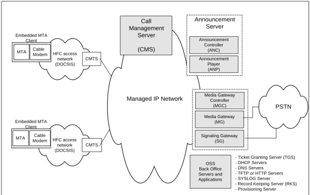
At a very high level, the PacketCable 1.0 architecture contains three networks: the “DOCSIS HFC Access Network”, the “Managed IP Network” and the PSTN. The Cable Modem Termination System (CMTS) provides connectivity between the “DOCSIS HFC Access Network” and the “Managed IP Network”. Both the Signaling Gateway (SG) and the Media Gateway (MG) provide connectivity between the “Managed IP Network” and the PSTN. The reference architecture for PacketCable 1.0 is shown in Figure 1.
Figure 1. PacketCable Reference Architecture
The DOCSIS HFC access network provides high-speed, reliable, and secure transport between the customer premise and the cable headend. This access network may provide all DOCSIS 1.1 capabilities including Quality of Service. The DOCSIS HFC access network includes the following functional components: the Cable Modem (CM), Multi-media Terminal Adapter (MTA), and the Cable Modem Termination System (CMTS). The Managed IP network serves several functions. First, it provides interconnection between the basic PacketCable functional components responsible for signaling, media, provisioning, and quality of service establishment. In addition, the managed IP network provides long-haul IP connectivity between other Managed IP and DOCSIS HFC networks. The Managed IP network includes the following functional components: Call Management Server (CMS), Announcement Server (ANS), several Operational Support System (OSS) back-office servers, Signaling Gateway (SG), Media Gateway (MG), and Media Gateway Controller (MGC).
Managed IP Network PSTN Call Management Server (CMS) HFC access network (DOCSIS) CMTS MTA Cable Modem Embedded MTA Client OSS Back Office Servers and Applications
- Ticket Granting Server (TGS) - DHCP Servers
- DNS Servers - TFTP or HTTP Servers - SYSLOG Server
- Record Keeping Server (RKS) - Provisioning Server Media Gateway Controller (MGC) Signaling Gateway (SG) Media Gateway (MG) HFC access network (DOCSIS) CMTS MTA Cable Modem Embedded MTA Client Announcement Controller (ANC) Announcement Player (ANP) Announcement Server
The individual network components that are shown in Figure 1 are described in detail in Section 3.
2.2 PacketCable Zones and Domains
MSO A Zone 1 MSO B Zone 3 MSO C Zone 4 Managed IP Backbone MSO A Zone 2 CMS CMS CMS V PSTN Gateway V V PSTN Gateways PSTN Gateway Administrative Domain 3 PSTN PSTN PSTN Administrative Domain 2 Administrative Domain 1
Figure 2. Zones and Administrative Domains
A PacketCable zone consists of the set of MTAs in one or more DOCSIS HFC access networks that are managed by a single functional CMS as shown in Figure 2. Interfaces between functional components within a single zone are defined in the PacketCable 1.0 specifications. Interfaces between zones (e.g., CMS-CMS) have not been defined and will be addressed in future phases of the PacketCable architecture. A PacketCable domain is made up of one or more PacketCable zones that are operated and managed by a single administrative entity. A PacketCable domain may also be referred to as an administrative domain. Interfaces between domains have not defined in PacketCable 1.0 and will be addressed in future phases of the PacketCable architecture.
2.3 PacketCable 1.0 Sp ecifications
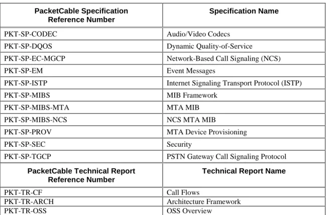
PacketCable 1.0 consists of the eleven Specifications and three Technical Reports shown in Table 1.
Table 1 PacketCable 1.0 Specifications and Reports
PacketCable Specification Reference Number
Specification Name
PKT-SP-CODEC Audio/Video Codecs
PKT-SP-DQOS Dynamic Quality-of-Service
PKT-SP-EC-MGCP Network-Based Call Signaling (NCS)
PKT-SP-EM Event Messages
PKT-SP-ISTP Internet Signaling Transport Protocol (ISTP)
PKT-SP-MIBS MIB Framework
PKT-SP-MIBS-MTA MTA MIB
PKT-SP-MIBS-NCS NCS MTA MIB
PKT-SP-PROV MTA Device Provisioning
PKT-SP-SEC Security
PKT-SP-TGCP PSTN Gateway Call Signaling Protocol
PacketCable Technical Report Reference Number
Technical Report Name
PKT-TR-CF Call Flows
PKT-TR-ARCH Architecture Framework
PKT-TR-OSS OSS Overview
2.4 PacketCable 1.0 De sign Considerations
In order to enable real-time multimedia communications across the cable network infrastructure, PacketCable specifications define protocols in the following areas:
• Call Signaling
• Quality of Service
• Media Stream Transport and Encoding
• Device Provisioning
• Event Messaging
• Security and Privacy
• Operational Support Systems
This section provides an overview of the high-level design goals and concepts used in developing the specifications that define the PacketCable 1.0 reference architecture. Individual PacketCable specifications should be consulted to obtain detailed protocol requirements for each of these areas.
2.4.1 General Architectural Goals
• Enable voice quality capabilities comparable to or better than the PSTN as perceived by the end-user.
• Provide a network architecture that is scalable and capable of supporting millions of subscribers.
• Ensure the one-way delay for local IP access and IP egress (i.e. excluding the IP backbone network) is less than 45ms.
• Support primary and secondary line residential voice communications capabilities.
• Leverage existing protocol standards. PacketCable strives to specify open, approved industry standards that have been widely adopted in other commercial communication networks. This includes protocols approved by the ITU, IETF, IEEE, Telcordia and other communications standards organizations.
• Leverage and build upon the data transport and Quality of Service capabilities provided by DOCSIS.
• Define an architecture that allows multiple vendors to rapidly develop low-cost interoperable solutions to meet Member time-to-market requirements.
• Ensure that the probability of blocking a call can be engineered to be less than 1% during the High Day Busy Hour (HDBH)
• Ensure that call cutoffs and call defects can be engineered to be less than 1 per 10,000 completed calls.
• Support modems (up to V.90 56 kb/s) and fax (up to 14.4 kbps)
• Ensure that frame slips due to unsynchronized sampling clocks or due to lost packets occur less than 0.25 per minute.
2.4.2 Call Signaling
• Define a network-based signaling paradigm.
• Provide end-to-end call signaling for the following call models:
• calls that originate from the PSTN and terminate on the cable network
• calls that originate on the cable network and terminate on the cable network within a single PacketCable zone
• calls that originate from the cable network and terminate on the PSTN
• Provide signaling to support custom calling features such as:
• Call Waiting
• Cancel Call Waiting
• Call Forwarding (no-answer, busy, variable)
• Voice mail Message Waiting Indicator
• Provide signaling to support Custom Local Area Signaling Services (CLASS) features such as:
• Calling Number Delivery
• Calling Name Delivery
• Calling Identity Delivery On Call Waiting
• Calling Identity Delivery Blocking
• Anonymous Call Rejection
• Automatic Callback
• Automatic Recall
• Distinctive Ringing/Call Waiting
• Customer Originated Trace
• Support a signaling paradigm consistent with existing IP telephony standards for use within a cable operator’s PacketCable network and when connecting to the PSTN.
• Ability to direct dial any domestic or international telephone number (E.164 address)
• Ability to receive a call from any domestic or international telephone number supported by the PSTN.
• Ensure that a new subscriber retains current phone number via Local Number Portability (LNP)
• Ability to use the IXC of choice for intra-LATA toll (local toll) and inter-LATA (long distance) calls. This includes pre-subscription and "dial-around" (10-1X-XXX).
• Support Call Blocking/Call Blocking Toll restrictions, (e.g. blocking calls to 900-, 976-, etc.)
2.4.3 Quality of Service
• Provide a rich set of policy mechanisms to provide and manage QoS for PacketCable services over the access network.
• Provide admission control mechanisms for both upstream and downstream directions.
• Allow dynamic changes in QoS in the middle of PacketCable calls.
• Enable transparent access to all of the QoS mechanisms defined in DOCSIS 1.1. PacketCable clients need not be aware of specific DOCSIS QoS primitives and parameters.
• Minimize and prevent abusive QoS usage including theft-of and denial-of service attacks. Ensure QoS policy is set and enforced by trusted PacketCable network elements.
• Provide a priority mechanism for 911 and other priority based signaling services.
2.4.4 CODEC and Media Str eam
• Minimize the effects that latency, packet-loss, and jitter have on voice-quality in the IP telephony environment.
• Define a minimum set of audio codecs that must be supported on all PacketCable endpoint devices (MTAs). Evaluation criteria for mandatory codecs are selected as those most efficient with respect to voice quality, bandwidth utilization, and implementation complexity.
• Accommodate evolving narrow-band and wide-band codec technologies.
• Specify echo cancellation and voice activity detection mechanisms.
• Support for transparent, error-free DTMF transmission and detection.
• Support terminal devices for the deaf and hearing impaired.
• Provide mechanisms for codec switching when fax and modem services are required.
2.4.5 Device Provisioning a nd OSS
• Support dynamic and static provisioning of customer premise equipment (MTA and Cable Modem).
• Provisioning changes should not require reboot of MTA.
• Allow dynamic assignment and management of IP addresses for subscriber devices
• Ensure that real-time provisioning and configuration of MTA software does not adversely affect subscriber service.
• Define SNMP MIBs for managing customer premise equipment (MTA).
2.4.6 Security
• Enable residential voice capabilities with the same or higher level of perceived privacy as in the PSTN.
• Provide protection against attacks on the MTA.
• Protect the MSO from various denial of service, network disruption and theft of service attacks.
• Design considerations include confidentiality, authentication, integrity, non-repudiation and access control.
3 PACKETCABLE FUNCTIONAL COMPONENTS
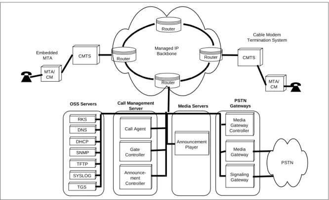
This section describes the functional components present in a PacketCable network. Component descriptions are not intended to define or imply product implementation requirements but instead to describe the functional role of each of these components in the reference architecture. Note that specific product implementations may combine functional components as needed. Not all components are required to be present in a PacketCable Network.
The PacketCable architecture contains trusted and untrusted network elements. Trusted network elements are typically located within a Cable Operator’s managed backbone network. Untrusted network elements, such as the CM and MTA, are typically located within the subscriber's home and outside of the MSO’s facility.
Managed IP Backbone MTA/ CM Router Router Router Router CMTS MTA/ CM CMTS Announcement Player Media Gateway Controller Media Gateway Signaling Gateway Media Servers PSTN Gateways PSTN Embedded MTA DNS DHCP SNMP TFTP RKS SYSLOG TGS OSS Servers Call Agent Gate Controller Call Management Server Announce-ment Controller Cable Modem Termination System
Figure 3. PacketCable Component Reference Model
3.1 Multimedia Termin al Adapter (MTA)
An MTA is a PacketCable client device that contains a subscriber-side interface to the subscriber’s CPE (e.g., telephone) and a network-side signaling interface to call control elements in the network. An MTA provides codecs and all signaling and encapsulation functions required for media transport and call signaling.
MTAs reside at the customer site and are connected to other PacketCable network elements via the HFC access network (DOCSIS). PacketCable 1.0 MTAs are required to support the Network Call Signaling (NCS) protocol.
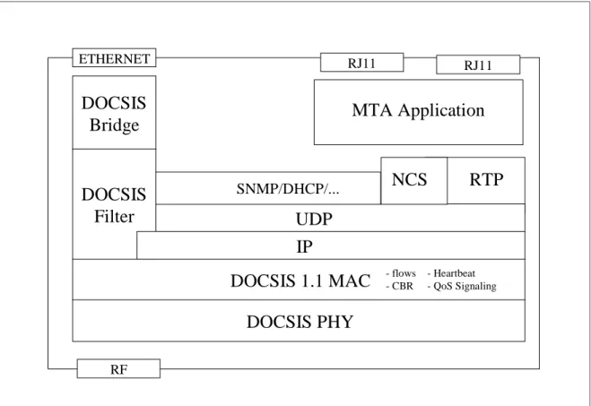
An embedded MTA (E-MTA) is a single hardware device that incorporates a DOCSIS 1.1 cable modem as well as a PacketCable MTA component. Figure 4 shows a representative functional diagram of an E-MTA.
PacketCable 1.0 specifications only require support for embedded MTAs. Throughout this report, unless otherwise noted, the term MTA refers to an embedded MTA.
3.1.1 MTA Functional Requ irements
An MTA is responsible for the following functionality:
• NCS call signaling with the CMS
• QoS signaling with the CMS and the CMTS
• Authentication, confidentiality and integrity of some messages between the MTA and other PacketCable network elements
• Mapping media streams to the MAC services of the DOCSIS access network
• Encoding/decoding of media streams
• Providing multiple audio indicators to phones, such as ringing tones, call-waiting tones, stutter dial tone, dial tone, etc.
• Standard PSTN analog line signaling for audio tones, voice transport, caller-id signaling, DTMF, and message waiting indicators
• The G.711 audio codec
• One or more RJ11 analog interface(s) as defined by Bellcore TR-909
Additional MTA functionality is defined in other PacketCable specifications such as NCS Signaling [5], Dynamic Quality-of-Service [4], Audio-Video Codecs [3], MIBS [8][9], and MTA Device Provisioning [12].
3.1.2 MTA identifiers
The following identifiers characterize the E-MTA:
• An embedded MTA has two MAC addresses, one for the cable modem and one for the MTA.
• An embedded MTA has two IP addresses, one for the cable modem and one for the MTA.
• An embedded MTA has two Fully Qualified Domain Names (FQDN), one for the cable modem and one for the MTA
• At least one telephone number per configured physical port
• Device capabilities
RF RJ11 RJ11
DOCSIS
Bridge
RTP
UDP
NCS
DOCSIS 1.1 MAC
DOCSIS PHY
ETHERNET SNMP/DHCP/...DOCSIS
Filter
- flows - CBRMTA Application
- Heartbeat - QoS SignalingIP
Figure 4. E-MTA Conceptual Functional Architecture
3.2 Cable Modem (CM)
The cable modem (CM) is a network element that is defined in the DOCSIS [19]. The CM is a modulator/demodulator residing on the customer premise that provides data transmission over the cable network using the DOCSIS protocol. In PacketCable, the CM plays a key role in handling the media stream and provides services such as classification of traffic into service flows, rate shaping, and prioritized queuing.
3.3 HFC Access Netwo rk
PacketCable-based services are carried over the Hybrid Fiber/Coax (HFC) access network. The access network is a bi-directional, shared-media system that consists of the Cable Modem (CM), the Cable Modem Termination System (CMTS), and the DOCSIS MAC and PHY access layers.
3.4 Cable Modem Term ination System (CMTS)
The CMTS provides data connectivity and complimentary functionality to cable modems over the HFC access network (DOCSIS). It also provides connectivity to wide area networks. The CMTS is located at the cable television system head-end or distribution hub.
• Providing the required QoS to the CM based upon policy configuration.
• Allocating upstream bandwidth in accordance to CM requests and network QoS policies.
• Classifying each arriving packet from the network side interface and assigning it to a QoS level based on defined filter specifications.
• Policing the TOS field in received packets from the cable network to enforce TOS field settings per network operator policy.
• Altering the TOS field in the downstream IP headers based on the network operator’s policy.
• Performing traffic shaping and policing as required by the flow specification.
• Forwarding downstream packets to the DOCSIS network using the assigned QoS.
• Forwarding upstream packets to the backbone network devices using the assigned QoS.
• Converting and classifying QoS Gate parameters into DOCSIS QoS parameters.
• Signaling and reserving any backbone QoS necessary to complete the service reservation.
• Recording usage of resources per call using PacketCable Event Messages.
3.4.1 CMTS Gate
The CMTS Gate is a functional component of the CMTS that performs traffic classification and enforces QoS policy on media streams as directed by the Gate Controller (GC).
3.5 Call Management S erver (CMS)
The Call Management Server provides call control and signaling related services for the MTA, CMTS, and PSTN gateways in the PacketCable network. The CMS is a trusted network element that resides on the managed IP portion of the PacketCable network.
A PacketCable 1.0 CMS consists of the following logical PacketCable components.
Call Agent (CMS/CA) – Call Agent is a term that is often used interchangeably with
CMS, especially in the MGCP. In PacketCable, the Call Agent (CA) refers to the control component of the CMS that is responsible for providing signaling services using the NCS protocol to the MTA. In this context, Call Agent responsibilities include but are not limited to:
• Implementing call features
• Maintaining call progress state
• Collecting and pre-processing dialed digits
• Collecting and classifying user actions
Gate Controller (CMS/GC) – The Gate Controller (GC) is a logical QoS
management component within the CMS that coordinates all quality of service authorization and control. Gate Controller functionality is defined in the Dynamic Quality of Service specification.
The CMS may also contain the following logical components:
Media Gateway Controller - The MGC is logical signaling management component
used to control PSTN Media Gateways. The MGC function is defined in detail later in this section.
Announcement Controller - The ANC is a logical signaling management
component used to control network announcement servers. The ANC function is defined in detail in Section 3.8.
The CMS may also provide the following functions:
• Call management and CLASS features
• Directory Services and Address translation
• Call routing
• Record usage of local number portability services
• Zone-to-Zone call signaling and QoS admission control
For the purposes of this specification, protocols that implement the functionality of the CMS are specified as terminating at the CMS – actual implementations may distribute the functionality in one or more servers that sit “behind” the Call Management Server.
3.6 PSTN Gateway
PacketCable allows MTA’s to inter-operate with the current PSTN through the use of PSTN Gateways.
In order to enable operators to minimize cost and optimize their PSTN interconnection arrangements, the PSTN Gateway is decomposed into three functional components:
• Media Gateway Controller (MGC) – The MGC maintains the call state and
controls the overall behavior of the PSTN gateway.
• Signaling Gateway (SG) – The SG provides a signaling interconnection function
between the PSTN SS7 signaling network and the IP network.
• Media Gateway (MG) – The MG terminates the bearer paths and transcodes
3.6.1 Media Gateway Contro ller (MGC)
The Media Gateway Controller (MGC) receives and mediates call-signaling information between the PacketCable network and the PSTN. It maintains and controls the overall call state for calls requiring PSTN interconnection.
The MGC controls the MG by instructing it to create, modify, and delete connections that support the media stream over the IP network. The MGC also instructs the MG to detect and generate events and signals such as continuity test tones for ISUP trunks, or MF signaling for MF trunks. Each trunk is represented as an endpoint.
The following is a list of functions performed by the Media Gateway Controller:
• Call Control Function – maintains and controls the overall PSTN Gateway call
state for the portion of a call that traverses the PSTN Gateway. The function interfaces with external PSTN elements as needed for PSTN Gateway call control, e.g., by generating TCAP queries.
• PacketCable Signaling – terminates and generates the call signaling from and to
the PacketCableside of the network.
• MG Control – The MG Control function exercises overall control of endpoints in
the Media Gateway:
• Event Detection instructs the MG to detect events, e.g., in-band tones and seizure state, on the endpoint and possibly connections.
• Signal Generation instructs the MG to generate in-band tones and signals on the endpoint and possibly connections.
• Connection Control instructs the MG on the basic handling of connections from and to endpoints in the MG.
• Attribute Control instructs the MG regarding the attributes to apply to an endpoint and/or connection, e.g., encoding method, use of echo cancellation, security parameters, etc.
• External Resource Monitoring – maintains the MGC’s view of externally
visible MG resources and packet network resources, e.g. endpoint availability.
• Call Routing – makes call routing decisions.
• Security – ensures that any entity communicating with the MGC adheres to the
security requirements.
• Usage Recording via Event Messages – records usage of resources per call.
3.6.2 Media Gateway (MG)
The Media Gateway provides bearer connectivity between the PSTN and the PacketCable IP network. Each bearer is represented as an endpoint and the MGC instructs the MG to set-up and control media connections to other endpoints on the PacketCable network. The MGC also instructs the MG to detect and generate events and signals relevant to the call state known to the MGC.
3.6.2.1 Media Gateway Function s
The following is a list of functions performed by the Media Gateway:
• Terminates and controls physical circuits in the form of bearer channels from the PSTN.
• Discriminates between media and Channel Associated In-band signaling information from the PSTN circuit.
• Detects events on endpoints and connections as requested by the MGC. This includes events needed to support in-band signaling, e.g., MF.
• Generates signals on endpoints and connections, e.g., continuity tests, alerting, etc. as instructed by the MGC. This includes signals needed to support in-band signaling.
• Creates, modifies, and deletes connections to and from other endpoints as instructed by the MGC.
• Controls and assigns internal media processing resources to specific connections upon receipt of a general request from the Media Gateway Controller.
• Performs media transcoding between the PSTN and the PacketCable network. This includes all aspect of the transcoding such as codecs, echo cancellation, etc.
• Ensures that any entity communicating with the MG adheres to the security requirements.
• Determines usage of relevant resources and attributes associated with those resources, e.g., number of media bytes sent and received.
• Reports usage of resources to the MGC.
3.6.3 Signaling Gateway (SG )
The Signaling Gateway function sends and receives circuit-switched network signaling at the edge of the PacketCable network. For PacketCable 1.0, the signaling gateway function only supports non-facility associated signaling in the form of SS7. Facility associated signaling in the form of MF is supported by the MG function directly.
3.6.3.1 SS7 Signaling Gateway Functions
The following is a list of functions performed by the Signaling Gateway function:
• Terminates physical SS7 signaling links from the PSTN (A, F links).
• Implements security features, to ensure that the Gateway security is consistent with PacketCable and SS7 network security requirements.
• Terminates Message Transfer Part (MTP) level 1, 2 and 3.
• Implements MTP network management functions as required for any SS7 signaling point.
• Performs ISUP Address Mapping to support flexible mapping of Point Codes (both Destination Point Code and Origination Point Code) and/or Point Code/CIC code combination contained within SS7 ISUP messages to the appropriate Media Gateway Controller (MGC) (either a domain name or an IP address). The addressed MGC will be responsible for controlling the Media Gateway, which terminates the corresponding trunks.
• Performs TCAP Address Mapping to map Point Code/Global Title/SCCP Subsystem Number combinations within SS7 TCAP messages to the appropriate Media Gateway Controller or Call Management Server.
• Provides mechanism for certain trusted entities (“TCAP Users”) within the PacketCable network, such as Call Agents, to query external PSTN databases via TCAP messages sent over the SS7 network.
• Implements the transport protocol required to transport the signaling information between the Signaling Gateway and the Media Gateway Controller.
3.7 OSS Back Office C omponents
The OSS back office contains business, service, and network management components supporting the core business processes. As defined by the ITU TMN framework, the main functional areas for OSS are fault management, performance management, security management, accounting management, and configuration management. These topics are covered in detail in the PacketCable OSS Framework Technical Report [15].
PacketCable 1.0 defines a limited set of OSS functional components and interfaces to support MTA device provisioning and Event Messaging to carry billing information.
3.7.1 TGS
For PacketCable, the term TGS (Ticket Granting Server) is utilized for a Kerberos server. The Kerberos protocol with the public key PKINIT extension is used for key management on the MTA-CMS interface [37].
The TGS grants Kerberos tickets to the MTA. A ticket contains information used to set up authentication, privacy, integrity and access control for the call signaling between the MTA and the CMS. This ticket is issued in three different scenarios.
• During device provisioning, the MTA requests a ticket from the TGS. It is strongly recommended that the MTA save Kerberos tickets in persistent storage. In the case when the MTA reboots, if the saved ticket is still valid, then the MTA will not need to execute the PKINIT to request a new ticket from the TGS.
• In normal operation, each time a ticket expires, the MTA will request a new ticket during the grace period from the TGS. Note: In the case of power failure in the CMS, the MTA will no longer be associated with this CMS. When this CMS restarts it will request “wake up” information from the MTA. If the ticket the MTA currently holds is beyond the expiration time, often referred to as a stale ticket, the MTA will request a new ticket from the TGS. If the MTA is still
holding a valid ticket then it should send this ticket to the CMS without requesting a new one from the TGS.
• When the TGS is not available on the network and the MTA can not get a new ticket during the grace period, the MTA must hold on to the current, but stale ticket until a TGS is available to grant a new ticket. The request from the MTA during this condition is specified in the PacketCable Security specification [13].
3.7.2 Dynamic Host Configu ration Protocol Server (DHCP)
The DHCP server is a back office network element used during the MTA device provisioning process to dynamically allocate IP addresses and other client configuration information.
3.7.3 Domain Name System Server (DNS)
The DNS server is a back office network element used to map between ASCII domain names and IP addresses.
3.7.4 Trivial File Transfer Pr otocol Server or HyperText Transfer Protocol Server (TFTP or HTTP)
The TFTP Server is a back office network element used during the MTA device provisioning process to download configuration files to the MTA. An HTTP Server may be used instead of a TFTP server to download configuration files to the MTA.
3.7.5 SYSLOG Server (SYSL OG)
The SYSLOG server is a back office network element used to collect events such as traps and errors from an MTA.
3.7.6 Record Keeping Serve r (RKS )
The RKS is a trusted network element component that receives PacketCable Event Messages from other trusted PacketCable network elements such as the CMS, CMTS, and MGC. The RKS also, at a minimum, is a short-term repository for PacketCable Event Messages. The RKS may assemble the Event Messages into coherent sets or Call Detail Records (CDRs), which are then made available to other back office systems such as billing, fraud detection, and other systems.
3.8 Announcement Se rver (ANS)
An Announcement Server is a network component that manages and plays informational tones and messages in response to events that occur in the network. An Announcement Server (ANS) is a logical entity composed of an Announcement Controller (ANC) and an Announcement player (ANP).
3.8.1 Announcement Contro ller (ANC)
The ANC initiates and manages all announcement services provided by the Announcement Player. The ANC requests the ANP to play announcements based on call state as determined by the CMS. When information is collected from the end-user by the ANP, the ANC is responsible for interpreting this information and manage the session accordingly. Hence, the ANC may also manage call state.
3.8.2 Announcement Player (ANP)
The Announcement Player is a media resource server. It is responsible for receiving and interpreting commands from the ANC and for delivering the appropriate announcement(s) to the MTA. The ANP also is responsible for accepting and reporting user inputs (e.g., DTMF tones). The ANP functions under the control of the ANC.
4 PROTOCOL INTE RFACES
Protocol specifications have been defined for most of the component interfaces in the PacketCable architecture. An overview of each protocol interface is provided within this section. The individual PacketCable specifications should be consulted for the complete protocol requirements.
It is possible that some of these interfaces may not exist in a given vendor’s product implementation. For example, if several functional PacketCable components are combined then it is possible that some of these interfaces are internal to that component.
4.1 Call Signaling Inter faces
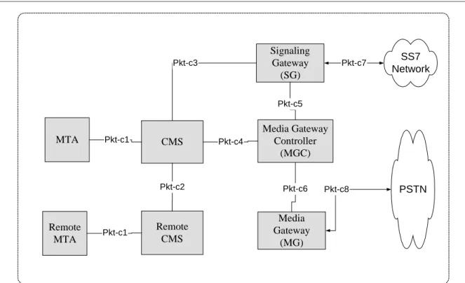
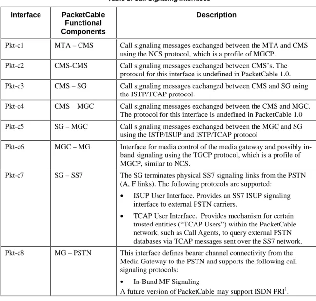
Call signaling requires multiple interfaces within the PacketCable architecture. These interfaces are identified in Figure 5. Each interface in the diagram is labeled, and further described in the subsequent Table 2.
PSTN Media Gateway (MG) Signaling Gateway (SG) CMS Pkt-c8 Pkt-c7 Pkt-c3 Pkt-c6 SS7 Network Remote CMS Pkt-c2 Media Gateway Controller (MGC) MTA Pkt-c1 Pkt-c5 Pkt-c4 Remote MTA Pkt-c1
Table 2. Call Signaling Interfaces
Interface PacketCable
Functional Components
Description
Pkt-c1 MTA – CMS Call signaling messages exchanged between the MTA and CMS using the NCS protocol, which is a profile of MGCP.
Pkt-c2 CMS-CMS Call signaling messages exchanged between CMS’s. The protocol for this interface is undefined in PacketCable 1.0. Pkt-c3 CMS – SG Call signaling messages exchanged between CMS and SG using
the ISTP/TCAP protocol.
Pkt-c4 CMS – MGC Call signaling messages exchanged between the CMS and MGC. The protocol for this interface is undefined in PacketCable 1.0 Pkt-c5 SG – MGC Call signaling messages exchanged between the MGC and SG
using the ISTP/ISUP and ISTP/TCAP protocol
Pkt-c6 MGC – MG Interface for media control of the media gateway and possibly in-band signaling using the TGCP protocol, which is a profile of MGCP, similar to NCS.
Pkt-c7 SG – SS7 The SG terminates physical SS7 signaling links from the PSTN (A, F links). The following protocols are supported:
• ISUP User Interface. Provides an SS7 ISUP signaling interface to external PSTN carriers.
• TCAP User Interface. Provides mechanism for certain trusted entities (“TCAP Users”) within the PacketCable network, such as Call Agents, to query external PSTN databases via TCAP messages sent over the SS7 network. Pkt-c8 MG – PSTN This interface defines bearer channel connectivity from the
Media Gateway to the PSTN and supports the following call signaling protocols:
• In-Band MF Signaling
A future version of PacketCable may support ISDN PRI1. 4.1.1 Network-based Call Si gnaling (NCS) Framework
The PacketCable Network-Based Call Signaling (NCS) protocol (Pkt-c1) is an extended variant of the IETF’s MGCP call signaling protocol. The NCS architecture places call state and feature implementation in a centralized component, the Call Management Server (CMS), and places device control intelligence in the MTA. The MTA passes device events to the CMS, and responds to commands issued from the CMS. The CMS, which may consist of multiple geographically or administratively distributed systems, is responsible for setting up and tearing down calls, providing advanced services [CLASS and custom calling features], performing call authorization, and generating billing event records, etc.
Examples of the partition of function would be for the CMS to instruct the MTA to inform the CMS when the phone goes off hook, and seven DTMF digits have been entered. When this sequence of events occur, the MTA notifies the CMS. The CMS
may then instruct the MTA to create a connection, reserve QoS resources through the access network for the pending voice connection, and also to play a locally generated ringback tone. The CMS in turn communicates with a remote CMS (or MGC) to setup the call. When the CMS detects answer from the far end, it instructs the MTA to stop the ringback tone, activate the media connection between the MTA and the far-end MTA, and begin sfar-ending and receiving media stream packets.
By centralizing call state and service processing in the CMS, the service provider is in a position to centrally manage the reliability of the service provided. In addition the service provider gains full access to all software and hardware in the event that a defect that impacts subscriber services occurs. Software can be centrally controlled, and updated in quick debugging and resolution cycles that do not require deployment of field personnel to the customer premise. Additionally, the service provider has direct control over the services introduced and the associated revenue streams associated with such services.
4.1.2 PSTN Signaling Frame work
PSTN signaling interfaces are summarized in Table 2 (Pkt-c3 through Pkt-c8). These interfaces provide access to PSTN-based services and to PSTN subscribers from the PacketCable network.
The PacketCable PSTN signaling framework consists of a PSTN gateway that is subdivided into three functional components:
• Media Gateway Controller (MGC)
• Media Gateway (MG)
• Signaling Gateway (SG)
The Media Gateway Controller and Media Gateway are analogous to, respectively, the CMS and MTA in the NCS framework. The Media Gateway provides bearer and in-band signaling connectivity to the PSTN. The Media Gateway Controller implements all the call state and intelligence and controls the operation of the Media Gateway through the TGCP protocol (pkt-c6). This includes creation, modification and deletion of connections as well as in-band signaling information to and from the MG. TGCP is an extended variant of the IETF’s MGCP call signaling protocol. The TGCP variant is closely aligned with NCS.
The CMS and the MGC may each send routing queries (e.g., 800 number lookup, LNP lookup) to an SS7 Service Control Point (SCP) via the SG (pkt-c3 and pkt-c5). The MGC, via the SG, also exchanges ISUP signaling with the PSTN’s SS7 entities for trunk management and control. The ISTP protocol provides the signaling interconnection service between the PacketCable network call control elements (Call Management Server and Media Gateway Controller) and the PSTN SS7 Signaling network through the SS7 Signaling Gateway. ISTP contains features for initialization; address mapping from the SS7 domain to the IP domain; message delivery for SS7 ISUP and TCAP; congestion management, fault management, maintenance operations; and redundant configuration support. ISTP bridges the gap between basic IP transport mechanisms and application level signaling. Although not a translation of
the SS7 MTP3 and SCCP protocols, ISTP implements analogues to some of the MTP3 and SCCP functions in a fashion appropriate to distributed systems communicating over an IP network. These capabilities allow the IP network to interact with and receive all the services of the PSTN. As service capabilities evolve over time, these same signaling capabilities may be used to support PSTN access to the PacketCable network’s own routing and service databases.
4.2 Media Streams
The IETF standard RTP (RFC 1899 - Real-Time Transport Protocol) is used to transport all media streams in the PacketCable network[32]. PacketCable utilizes the RTP profile for audio and video streams as defined in RFC 1990[35].
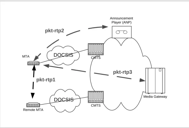
The primary media flow paths in the PacketCable network architecture are shown in Figure 6 and are further described below.
DOCSIS CMTS Media Gateway Remote MTA CMTS Announcement Player (ANP) DOCSIS pkt-rtp1 pkt-rtp3 pkt-rtp2 MTA
Figure 6. RTP Media Stream Flows in a PacketCable Network
pkt-rtp1: Media flow between MTAs. Includes, for example, encoded voice, video,
and fax.
pkt-rtp2: Media flow between the ANP and the MTA. Includes, for example, tones
and announcements sent to the MTA by the Announcement Player.
pkt-rtp3: Media flow between the MG and the MTA. Includes, for example, tones,
RTP encodes a single channel of multimedia information in a single direction. The standard calls for an 8-byte header with each packet. An 8-bit RTP “Payload Type” is defined to indicated which encoding algorithm is used. Most of the standard audio and video algorithms are assigned to particular PT values in the range 0 through 95. The range 96 through 127 is reserved for “dynamic” RTP payload types. The range 128 through 255 is reserved for private administration.
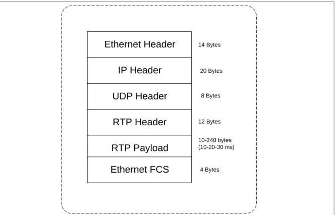
The packet format for RTP data transmitted over IP over Ethernet is depicted in Figure 7 below. Ethernet Header RTP Header RTP Payload Ethernet FCS IP Header UDP Header 14 Bytes 20 Bytes 8 Bytes 12 Bytes 10-240 bytes (10-20-30 ms) 4 Bytes
Figure 7. RTP Packet Format
The length of the RTP Payload as well as the frequency with which packets are transmitted depends on the algorithm as defined by the Payload Type field.
RTP sessions are established dynamically by the endpoints involved, so there is no “well-known” UDP port number. The Session Description Protocol (SDP) was developed by the IETF to communicate the particular IP address and UDP port an RTP session is using.
The packet header overhead of Ethernet, IP, UDP, and RTP is significant when compared to a typical RTP Payload size, which can be as small as 10 bytes for packetized voice. The DOCSIS 1.1 specification addresses this issue with a Payload Header Suppression feature for abbreviating common headers.
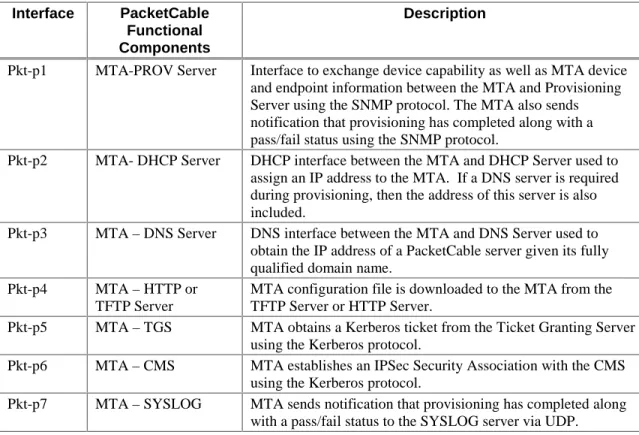
4.3 MTA Device Provis ioning
The scope of MTA Device Provisioning is to enable a MTA to register and provide subscriber services over the HFC network. Provisioning covers initialization, authentication, and registration functions required for MTA device provisioning. The Provisioning Specification [12] also includes attribute definitions required in the MTA configuration file. DHCP Server Provisioning Server DNS Server TGS SYSLOG Server CMS TFTP or HTTP Server Embedded-MTA pkt-p1 pkt-p2 pkt-p3 pkt-p4 pkt-p5 pkt-p6 pkt-p7
Figure 8. PacketCable Provisioning Interfaces
Table 3 describes the provisioning interfaces shown in the above diagram.
Table 3. Device Provisioning Interfaces
Interface PacketCable
Functional Components
Description
Pkt-p1 MTA-PROV Server Interface to exchange device capability as well as MTA device and endpoint information between the MTA and Provisioning Server using the SNMP protocol. The MTA also sends notification that provisioning has completed along with a pass/fail status using the SNMP protocol.
Pkt-p2 MTA- DHCP Server DHCP interface between the MTA and DHCP Server used to assign an IP address to the MTA. If a DNS server is required during provisioning, then the address of this server is also included.
Pkt-p3 MTA – DNS Server DNS interface between the MTA and DNS Server used to obtain the IP address of a PacketCable server given its fully qualified domain name.
Pkt-p4 MTA – HTTP or
TFTP Server
MTA configuration file is downloaded to the MTA from the TFTP Server or HTTP Server.
Pkt-p5 MTA – TGS MTA obtains a Kerberos ticket from the Ticket Granting Server using the Kerberos protocol.
Pkt-p6 MTA – CMS MTA establishes an IPSec Security Association with the CMS using the Kerberos protocol.
Pkt-p7 MTA – SYSLOG MTA sends notification that provisioning has completed along with a pass/fail status to the SYSLOG server via UDP.
4.4 SNMP Element Man agement Layer Interfaces
PacketCable requires SNMPv3 to interface the MTA to element management systems for MTA device provisioning. SNMPv3 ”traps” and “informs” are supported for event handling, as well as “sets” and “gets” for provisioning. PacketCable MIBs are defined in the MTA MIB specification [8] and the NCS MIB specification [9].
The PacketCable NCS MIB contains Network Call Signaling information for provisioning on both a device and a per endpoint basis. The MTA MIB contains data for device provisioning and for supporting provisioned functions such as event logging. More detailed information on the MIBs framework can be found in the PacketCable MIBs framework specification [10].
4.5 Event Messages In terfaces
4.5.1 Event Message Frame work
An Event Message is a data record containing information about network usage and activities. A single Event Message may contain a complete set of data regarding usage or it may only contain part of the total usage information. When correlated by the Record Keeping System (RKS), information contained in multiple Event Messages provides a complete record of the service. This complete record of the service is often referred to as a Call Detail Record (CDR). Event Messages or CDRs may be sent to one or more back office applications such as a billing system, fraud detection system, or pre-paid services processor.
This PacketCable Event Messages specification defines the structure of the Event Message data record and defines RADIUS as the transport protocol. Event Message data record is designed to be flexible and extensible in order to carry information about network usage for a wide variety of services. Additional transport protocols may be recommended in future releases of this specification. Although the scope of the specification is limited to defining Event Messages for basic residential voice capabilities, it is expected that this specification will be expanded to support additional PacketCable-based services. Figure 9 shows a representative Event Message architecture.
PacketCable Event Messages
Network Element Network Element Network Element RKS Event Messages Event Messages Event Messages PacketCable Non-PacketCable •Real-Time Billing Systems •Fraud Detection •Inter-Carrier •Pre-Paid Services •Legacy BillingFigure 9. Representative Event Messages Architecture
CMTS pkt-em3 pkt-em4 pkt-em5 Record Keeping Server MGC CMS pkt-em1* pkt-em2*
Note: * indicates that the Billing Correlation ID and other billing data is carried on an existing signaling interface.
Figure 10. Event Message Interfaces
The following table describes the Event Message interfaces shown in Figure 9.
Table 4. Event Message Interfaces
Interface PacketCable
Functional Component
Description
pkt-em1 CMS-CMTS DQoS Gate-Set message carrying Billing Correlation ID and other data required for CMTS to send Event Messages to an RKS.
Pkt-em2 CMS-MGC Vendor-proprietary interface carrying Billing Correlation ID and other data required billing data. Either the CMS or MGC
Interface PacketCable Functional Component
Description
may originate a call and therefore need to create the Billing Correlation ID and send this data to the other.
Pkt-em3 CMS-RKS RADIUS protocol carrying PacketCable Event Messages. Pkt-em4 CMTS-RKS RADIUS protocol carrying PacketCable Event Messages. Pkt-em5 MGC-RKS RADIUS protocol carrying PacketCable Event Messages.
4.6 Quality-of-Service (QoS)
4.6.1 QoS Framework
Quality of Service signaling interfaces are defined between many of the components of the PacketCable network. Signaling may be handled at the application layer (e.g. SDP parameters), network layer (e.g. RSVP), or the data-link layer (e.g. DOCSIS 1.1 QoS).
From the perspective of the MTA and its access network the PacketCable QoS Framework is represented in Figure 11:
Gate Controller
PacketCable Network - QoS Signaling Interfaces
Pkt-q4 CMTS CM MTA Record Keepking Server Record Keeping Server Gate Controller CMTS CM MTA Pkt-q2 Pkt-q7 Pkt-q2 Pkt-q1 Pkt-q6 Pkt-q5 Pkt-q5 Pkt-q1 Pkt-q6 Pkt-q4 Pkt-q3 Pkt-q3
Note: Gate Controller is a function contained within a CMS node.
Figure 11. PacketCable QoS Signaling Interfaces
Table 5 briefly identifies each interface and how each interface is used in the Dynamic QoS Specification (DQoS). Two alternatives are shown for this specification: first a general interface that is applicable to either embedded or
standalone MTAs; and second, an optional interface that is available only to embedded MTAs.
Table 5. QoS Interfaces for Standalone and Embedded MTAs
Interface PacketCable Functional Components
DQoS Embedded/ Standalone MTA
D-QoS Embedded MTA
Pkt-q1 MTA – CM N/A E-MTA, MAC Control
Service Interface Pkt-q2 CM – CMTS (DOCSIS) DOCSIS, CMTS-initiated DOCSIS, CM-initiated
Pkt-q3 MTA – CMTS RSVP+2 N/A
Pkt-q4 MTA – GC/CMS NCS/DCS NCS
Pkt-q5 GC – CMTS Gate Management Gate Management
Pkt-q6 CMTS – RKS Billing Billing
Pkt-q7 CMTS – CMTS Gate Management Gate Management
The function of each QoS interface is further described is defined in Table 6 below.
Table 6. QoS Interfaces
Interface PacketCable Functional Components
Description
Pkt-q1 MTA – CM This interface is only defined for the embedded MTA. The interface decomposes into three sub-interfaces:
Control: used to manage DOCSIS service-flows and their associated QoS
traffic parameters and classification rules.
Synchronization: used to synchronize packet and scheduling for
minimization of latency and jitter.
Transport: used to process packets in the media stream and perform
appropriate per-packet QoS processing.
The MTA/CM interface is conceptually defined in Appendix E of the DOCSIS RFI specification.
Pkt-q2 CM – CMTS This is the DOCSIS QoS interface (control, scheduling, and transport). It should be noted that, architecturally, control functions can be initiated from either the CM or the CMTS. However the CMTS is the final policy arbiter and granter of admission into the DOCSIS access network. The following capabilities of the DOCSIS MAC are used within PacketCable:
Multiple service flows, each with its own class of upstream traffic, both single and multiple voice connections per DOCSIS service flow
Prioritized classification of traffic streams to service flows.
Guaranteed minimum/constant bitrate scheduling service
Constant bit rate scheduling with traffic activity detection service
2
For PacketCable 1.0, only the embedded MTA interfaces as defined in Section 4 of the Dynamic Quality of Service specification are required. The CMTS is not required to support RSVP across the MTA-CMTS
Interface PacketCable Functional Components
Description
(slow down, speed up, stop, and restart scheduling)
DOCSIS packet header suppression for increased call density
DOCSIS classification of voice flows to service flow
DOCSIS synchronization of CODEC to CMTS clock and Grant Interval
Two-phase activation of QoS resources
TOS packet marking at network layer
Guarantees on latency and jitter.
Internal sub-layer signaling between PacketCable MTA and DOCSIS (embedded MTA)
This interface is further defined in the DOCSIS RFI specification. Pkt-q3 MTA – CMTS The interface is used for request of bandwidth and QoS resources related
to the bandwidth. The interface runs on top of layer 4 protocols that bypass the CM. As a result of message exchanges between the MTA and CMTS, service flows are activated using CMTS-originated signaling on interface PKT-Q2. An enhanced version of RSVP is utilized for this signaling.
Pkt-q4 MTA –
CMS/GC
Signaling interface between the MTA and CMS/GC. Many parameters are signaled across this interface such as media stream, IP addresses, and Codec selection, but it is possible for certain protocols to either derive QoS semantics from the signaling, or to extend the application layer signaling protocol to contain explicit QoS signaling parameters.
Pkt-q5 CMS/GC –
CMTS
This interface is used to manage the dynamic Gates for media stream bearer channels. This interface enables the PacketCable network to request and authorize QoS changes without requiring any layer two DOCSIS access network QoS control functions in MTA.
When supporting standalone MTAs no new client-side QoS signaling protocol needs to be designed. The GC/CMS takes responsibility for requesting policy, and the CMTS takes responsibility for access control and quickly setting up QoS on the DOCSIS access link.
Pkt-q6 CMTS – RKS This interface is used by the CMTS to signal to the RKS all changes in call authorization and usage. This interface is defined in the Event Messages specification.
Pkt-q7 CMTS –
CMTS
This interface is used for coordination of resources between the CMTS of the local MTA and the CMTS of the remote MTA. The CMTS is
responsible for the allocation and policing of local QoS resources. 4.6.2 Layer Two vs. Layer F our MTA QoS Signaling
QoS signaling from the MTA can be performed either at layer two (DOCSIS) or layer four (RSVP). Layer two signaling is accessible to CM and CMTS devices that exist at the RF boundary of the DOCSIS access network. Layer four signaling is required for devices that are one or more hops removed from the RF boundary of the DOCSIS access network.
If layer two QoS signaling is initiated by the MTA, the MTA must be an embedded MTA. The MTA utilizes the implicit interface for controlling the DOCSIS MAC service flows as suggested by Appendix E of the DOCSIS 1.1 RFI specification. Layer four QoS signaling is initiated by the MTA; the MTA may be either an embedded MTA or standalone MTA. Enhanced RSVP is used for this signaling and is intercepted by the CMTS. The CMTS utilizes layer two QoS signaling to communicate QoS signaling changes to the CM.
4.6.3 Dynamic Quality-of-Se rvice
PacketCable Dynamic QoS (D-QoS) utilizes the call signaling information at the time that the call is made to dynamically authorize resources for the call. Dynamic QoS prevents various theft of service attack types by integrating the QoS messaging with other protocols and network elements. The network elements that are necessary for a Dynamic QoS control are shown in Figure 11.
The function within the CMTS that performs traffic classification and enforces QoS policy on media streams is called a Gate. The Gate Controller element manages Gates for PacketCable media streams. The following key information is included in signaling between the GC and the CMTS:
• Maximum Allowed QoS Envelope – The maximum allowed QoS envelope
enumerates the maximum QoS resource (e.g., “2 grants of 160 bytes per 10ms”) the MTA is allowed to admit for a given media stream bearer flow. If the MTA requests a value greater than the parameters contained within the envelope the request will be denied.
• Identity of the media stream endpoints – The GC/CMS authorizes the parties
that are involved in a media stream bearer flow. Using this information the CMTS can police the data stream to ensure that the data stream is destined and originated from the parties that are authorized.
• Billing Information – The GC/CMS creates opaque billing information that the
CMTS does not have to decode. The information might be as simple as billing identity or the nature of the call. The CMTS forwards this billing information to the RKS as the call is activated or terminated.
The role of each of the PacketCable components in implementing D-QoS is as follows:
Call Management Server/Gate Controller – The CMS/GC is responsible for QoS
authorization. The QoS authorization might depend on the type of call, type of user or other parameters defined by policy.
CMTS – Using information supplied by the GC/CMS the CMTS performs admission
control on the QoS requests and at the same time polices the data stream to make sure that the data stream is originated and sent to authorized-media stream parties. The CMTS interacts with CM, RKS, MTA, and Terminating CMTS. The responsibilities of CMTS with respect to each of these elements is:
• CMTS to CM – The CMTS is responsible of setting up and tearing down service flows in such a way that the service level agreement it made with the MTA is met. Inasmuch as the CMTS does not trust the CM it polices the traffic from the CM such that the CM works in the way CMTS requested.
• CMTS to Record Keeping Server – The CMTS updates the Record Keeping Server (RKS) each time there is a change in the QoS Service Level Agreement between CMTS and MTA. It uses the Billing Information that is given by GC/CMS to identify each authorized QoS link. The CMTS puts timing information in the message it sends and also buffers the messages if the connection to RKS is severed.
• CMTS to MTA – The MTA makes dynamic requests for modification of QoS traffic parameters. When the CMTS receives the request it makes an authorization check to find out whether the requested characteristics are within the authorized QoS envelope and also whether the media stream endpoints are authorized. Then it provisions the QoS attributes for the RFI link on the CMTS and activates the appropriate QoS traffic parameters via signaling with the CM. When all the provisioning and authorization checks succeed the CMTS sends a success message to the GC/CMS indicating that MTA and CMTS are engaged in a Service Level Agreement.
• CMTS to Terminating CMTS – The CMTS sends messages to the terminating end CMTS (or other terminating access networking device) to ensure that the committed bandwidth on both sides is the same. If the committed bandwidth is not the same then both sides close the connection.
Cable Modem (CM) – Even though the CM is an untrusted entity the CM is
responsible for the correct operation of the QoS link between itself and the CMTS. The CMTS makes sure that the CM cannot abuse the RFI link, but it is the responsibility of the CM to utilize the RFI link to provide services that are defined by the DOCSIS 1.1 specification.
Record Keeping Server (RKS) – The RKS acts as a database and stores each event
as sent by the CMTS. The RKS stores the messages by attaching received time and network element information. The RKS has to have sufficient interface and/or processing power to allow additional processing to be done.
MTA – The MTA is the entity to which the Service Level Agreement is provided by
the access network. The MTA is responsible for the proper use of the QoS link. If it exceeds the traffic authorized by the SLA than it the MTA will not receive the QoS characteristics that it requested. The MTA uses two stage QoS bandwidth allocation – while the call origination is proceeding the QoS resources are admitted, then when the call is answered the resources are activated.
4.7 Announcement Se rvices
Announcements are typically needed for calls that do not complete. Additionally, they may be used to provide enhanced information services to the caller (e.g., calling card, n11 services, etc.). The signaling interfaces to support PacketCable Announcement Services are shown in Figure 12 and are summarized in Table 7 below. Announcement Player (ANP) CMS Announcement Controller (ANC)
MTA Ann-1 Ann-3
Announcement Server (ANS)
Ann-4 Ann-1 Media Gateway (MG) Ann-2 Ann-5 Media Gateway Controller (MGC) PSTN Ann-4