Tenor Carrier MultiPath
Product Guide
P/N 480-0005-00-18
T
able of Contents
About this Guide
What’s included? . . . 1-2 Typographical Conventions . . . 1-3 Product Guide Conventions . . . 1-3 Finding Help. . . 1-4
Chapter 1: Overview
What is Tenor CMS? . . . 1-2 Features. . . 1-3 Unique Design . . . 1-3 State-of-the-Art Configuration and Network Management . . . 1-3 SelectNet™ Technology Safety Net . . . 1-3 Dynamic Call Routing . . . 1-4 Multiple Channels/Signaling Supported . . . 1-4 Fractional T1/E1 Support . . . 1-4 PacketSaver™ . . . 1-5 IVR/RADIUS support . . . 1-5 Easy Connect to Console . . . 1-5 H.323 Gatekeeper Call Control Management . . . 1-5 Powerful System Monitoring . . . 1-6 Capabilities . . . 1-7 Intra-trunk Routing - “Hairpinning” . . . 1-8 Other Call Routing Options . . . 1-9 Virtual Tie Line . . . 1-9 Hop-off PBX Call . . . 1-10 SNMP Support . . . 1-10 Call Detail Recording . . . 1-10 H.323 Gatekeeper Services. . . 1-11 Gatekeeper . . . 1-11 Zone Management . . . 1-11 Call Registration. . . 1-11 Border Element . . . 1-11 Call Services . . . 1-12 SIP User Agent . . . 1-13
Board interoperability . . . 2-2 Chassis - CMS (14 Slot) . . . 2-3 Front (with AC power) . . . 2-3 Rear (with AC power). . . 2-4 Front (with DC Power) . . . 2-5 Rear (with DC power) . . . 2-6 Chassis - CMS960 (8 Slot) . . . 2-7 Front (with AC power) . . . 2-7 Rear (with AC power). . . 2-8 Front (with DC Power) . . . 2-9 Rear (with DC power) . . . 2-10 Chassis- CMS240 (2 slot) . . . 2-11 Front View (with AC power) . . . 2-11 Rear View (with AC power) . . . 2-12 Front view (with DC power) . . . 2-13 Rear View (with DC power) . . . 2-14 System Controller Card (Available for CMS P1.5.x ) . . . 2-15 CPU Card (Available for CMS P2.x.x) . . . 2-18 Front View . . . 2-19 Rear View . . . 2-20 WAN Cards . . . 2-22 DS1 WAN Card (with DSP module) . . . 2-22 T1 WAN Card. . . 2-25 E1 WAN Card . . . 2-27 DSP Resource Card . . . 2-29 Cables . . . 2-31 RJ-45 Cables . . . 2-31 RJ-48 Cables . . . 2-33 DB-9 to DB-9 Null Modem Cable (for System Controller card) . . . 2-35 DB-9 Serial RS-232 Cable (for CPU card) . . . 2-36
Pre-Installation Guidelines . . . 3-2 Inspect Package Contents . . . 3-2 Install in Rack. . . 3-2 Connection. . . 3-5 Introduction . . . 3-5 Connect to Trunk Interface - PSTN . . . 3-5 Connect to Line Interface - PBX . . . 3-6 Connect to Ethernet LAN (with System Controller Card) . . . 3-7 Connect to Ethernet LAN (with CPU Card) . . . 3-8 Connect to PC Console (with System Controller) . . . 3-9 Connect to PC Console (with CPU) . . . 3-10 Connect Power - CMS (14 slot), DC only . . . 3-11 Power Requirements . . . 3-11 Material Requirements . . . 3-11 Connect Power . . . 3-11 Connect Power - CMS960 (8 slot) and CMS240 (2 slot), DC only . . . 3-14 Power Requirements . . . 3-14 Material Requirements . . . 3-14 Connect Power . . . 3-14 Install Power Cord Strain Relief (AC only) . . . 3-16 Power up the System (for AC unit) . . . 3-17 Prevent Electrostatic Discharge Damage . . . 3-18 ESD Antistatic Wrist Strap . . . 3-18 Provide Grounding . . . 3-18 Assign IP Address . . . 3-19 Install Software Upgrade via CMS Software Update Utility . . . 3-21 Upgrade from Disk . . . 3-21 Upgrade via Network . . . 3-23 Backup . . . 3-23 Restore previous versions . . . 3-24
Chapter 4: Getting Started with Configuration
Overview . . . 4-2 Tenor Configuration Manager . . . 4-3 Getting Started with Configuration . . . 4-3 Tenor Monitor . . . 4-4 Getting Started with Monitoring . . . 4-4 Command Line Interface (CLI) . . . 4-5 Options. . . 4-5
Access CLI. . . 4-6 Telnet Connection . . . 4-6 Serial Port Connection . . . 4-6 Configuration via CLI . . . 4-7
Chapter 5: Call Detail Recording
Overview . . . 5-2 Establish connection between Tenor CMS and CDR Server . . . 5-3 Configure Tenor CMS for connection to CDR server. . . 5-4 Setup CDR Server and assign password . . . 5-4 Change CDR Password (if required) . . . 5-4 Tenor CMS Establishes Connection with CDR Server . . . 5-5 CDR Server Establishes Connection with Tenor CMS . . . 5-5 CDR Output . . . 5-6 Sample Record for Standard and Extended CDR Format 0, 1, 100, 101 . . . 5-6 Sample Record for Extended CMS CDR Format 3, 4, 103, 104:. . . 5-9
Chapter 6: System Alarms
Monitor Alarms. . . 6-2 How to Read Alarms . . . 6-2 Valid Alarms . . . 6-4 View Alarms . . . 6-8 Display all Alarms . . . 6-8 Display Active Alarms . . . 6-8 Display Alarm History. . . 6-9
Chapter 7: Diagnostics/Maintenance
Before you Begin . . . 7-2 Diagnostics . . . 7-3 Common Symptoms/Problems . . . 7-3 Unit Provisioning . . . 7-4 Ping Unit . . . 7-4
Clean/Replace Foam Air Filter (for CMS, 14 slot only) . . . 7-11 Reset System. . . 7-12 Change Password . . . 7-12 Card Maintenance/Replacement . . . 7-13 Replace WAN/System Controller/CPU cards of identical type . . . 7-14 Replace/Change DSP Module (on DS1 card) . . . 7-16 Move card location or change card type . . . 7-19 If you need Additional Help . . . 7-20
Appendix A: Getting Acquainted with Tenor CMS in the VoIP Network
How does CMS fit in the VoIP Network? . . . A-2 Common Network Types . . . A-3 Typical CMS Applications . . . A-4 Enterprise Network . . . A-4 Service Provider Network . . . A-5 Calling Card Application. . . A-6 Off Premises Exchange (OPX) . . . A-7
Appendix B: Specifications/Approvals
Voice/Fax. . . B-2 Line Side (PBX) / Trunk Side (PSTN) Connections . . . B-2 LAN Connection. . . B-3 Physical . . . B-3 Electrical . . . B-3 Environmental . . . B-3 Agency Approvals . . . B-4 FCC WARNINGS. . . B-6
GLOSSARY
INDEX
WARRANTY
What’s included?
This product guide is divided into chapters; each chapter describes a specific topic. The following chapters are included:
• About this Guide: Describes what is included in the Product Guide, including typographical conventions. • Chapter 1: Overview. Includes a general overview of the product, including a description of the Tenor
CMS’s features and capabilities.
• Chapter 2: Hardware Components. Hardware description, including the chassis, WAN cards (T1, E1, DS1), DSP Resource cards and the CPU/System Controller Card.
• Chapter 3: Installation. Describes how to install the Tenor CMS unit, including how to connect, power up and assign the IP address.
• Chapter 4: Getting Started via Configuration. This chapter tells you how to access the Tenor Configura-tion Manager, Tenor Monitor, and Command Line Interface (CLI) for configuraConfigura-tion opConfigura-tions.
• Chapter 5: Call Detail Recording. Describes the Call Detail Recording (CDR) feature, including how to set up the CDR server and assign a password. In addition, instructions for reading CDR output is also included.
• Chapter 6: System Alarms. Describes how to monitor and view alarms via Command Line Interface (CLI).
• Chapter 7:Diagnostics/Maintenance. Describes how to troubleshoot and monitor the health of the sys-tem.
• Appendix A: Getting Acquainted with Tenor CMS in the VoIP Network. A general overview of VoIP and how it relates to the Tenor CMS switch.
• Appendix B: Specifications/Approvals: A list of Tenor CMS’s specifications and approvals.
• Glossary • Index • Warranty
Typographical Conventions
Product Guide Conventions
Certain typographical conventions are used throughout this product guide. See below.
• All commands you enter via keystrokes appear in bold (e.g., Press Enter or Press Ctrl-I).
• All text commands you enter via Telnet session or command line typing appear in italics (e.g., type
active).
• There are three types of special text that are designed to reveal supplemental information: Note, Warn-ing, and Caution. See below.
A NOTE provides additional, helpful information. This information may tell you how to do a certain
task or just be a reminder for how-to’s given in previous sections. (i.e., For a list of valid commands at any time, type ?)
A WARNINGprovides information about how to avoid harm to your VoIP equipment or other
equip-ment (i.e., Do not stack more than 4 units together.)
A CAUTION provides information about how to avoid injury to yourself or to others (e.g., Do not install
Finding Help
Refer to the Product Guide for help. The Table of Contents and Index tells you where to find information eas-ily; the glossary defines specific terms. See Appendix A: Getting Acquainted with Tenor CMS in the VoIP Net-work for detailed information about VoIP terms and concepts.
Extensive configuration help is available via the Command Line Interface help system. Just type help or ?
C
hapter 1: Overview
This chapter gives you a general overview of the Tenor® Carrier MultiPath Switch (CMS), including feature descriptions and capabilities. You will also find information about the organization of this product guide. Specifically, the following topics are covered:
!
A description of Tenor CMS!
Typical implementationsWhat is Tenor CMS?
The Tenor Carrier MultiPath Switch (CMS) is a high-density VoIP (Voice over Internet Protocol) H.323/SIP switch that digitizes voice and fax data and transmits it over the IP network. Tenor CMS is available in three configurations: CMS (14 slot), CMS960 (8 slot), and CMS240 (2 slot); each is a slotted, scalable system that intelligently switches calls over both the IP network and the PSTN in order to ensure high quality voice. Tenor CMS functions as a gateway, gatekeeper, and a border element. The gateway converts circuit switched calls to VoIP calls, the gatekeeper performs IP call routing functions, and the border element distributes the call rout-ing directories throughout the network.
Each Tenor CMS is available with either AC or DC input power.
NOTE: Figure 1-1 illustrates Tenor units with AC power.
Figure 1-1
Tenor CMS VoIP Switch
The slotted system architecture boasts peripheral cards, which interface to various Wide Area Networks (WANs). Tenor CMS connects to T1/E1 lines operating in either a trunk circuit or line circuit configuration. The individual spans within the Tenor CMS may connect to either the PSTN or to T1/E1 termination equip-ment on the user premises (i.e., PBX).
The high performance System Controller/CPU card provides up to four 10/100BaseT connections and one RS-232 serial port connection; this card is an intelligent call routing engine which regulates system resources and configuration while coordinating all voice traffic activity in the unit. The DS1, T1, and E1 cards provide connections. The DS1 card also provides DSP processing (DSP is a signal processing resource; it performs
CMS (14 Slot)
CMS960 (8 Slot)
A.C. Power Supply
Power QUINTUM TEC H N O LO GIES, IN C . TM TE CHNO L OGIE S, I NC . QU IN T U M TM Ho t S w ap DS 1 Sp a n St a tus 4 8 3 7 2615 10 /1 00 Et h e rne t DS P Li nk Al a rm CP U 1 1 2 2 Ba n k TX /R X St a tus PC I TECH NO LOG IE S, IN C. QU IN T U M TM CP U 4 8 3 7 2615 Al a rm CP U 2 St a tu s PC I Res e t 10 /1 00 Et h e rne t Li n k TX /RX Ho t S w ap CMS240 (2 Slot) 0 1 Reset+3.3V +5V +12V -12V QUINTUM TECHNOLOGIES, INC. TM QUINTUM TECHNOLOGIES, INC. TM TM Fault Fault TM Ground Strap Status Alarm CPUPCI Reset 10/100 Ethernet Link TX/RX 1 2 3 4 QUINTUMTM TECHNOLOGIES, INC. H ot Swap CPU Hot Swap DS1 Status Alarm 1 2 PCI CPU Bank DSP 1 2 TX/RX Link 1 2 3 4 5 6 7 8 10/100 Ethernet Span Status TECHNOLOGIES, INC. QUINTUMTM
A.C. Power Supply
Power QUINTUM TEC H N OL O G IES, IN C . TM QUINTUM TEC H N OL O G IES, IN C . TM TE CHN OL OGIE S , INC. QU IN T U M TM Ho t S w ap DS 1 Sp a n St a tus 4 8 3 7 2615 10/ 100 Et h e rne t DS P Li nk Al a rm CP U 1 1 2 2 Ba n k TX /RX St a tus PC I
A.C. Power Supply
Power QUINTUM TEC H N OL O G IES, IN C . TM TECH NO LO GIE S, I NC . QU IN T U M TM CP U 4 8 3 7 2615 Al a rm CP U 2 St a tu s PC I R eset 10/ 100 Et h e rn et Li nk TX /RX Ho t S w ap
A.C. Power Supply
Power QUINTUM TEC H N OL O G IES, IN C . TM TECH NO LOG IE S, I NC. QU IN T U M TM Ho t S w ap DS 1 Sp an St a tu s 4 8 3 7 2615 10/ 100 Et h e rn e t DS P Li nk Al a rm CP U 1 1 2 2 Ba nk TX /R X St a tus PC I TECH NO L OG IE S, IN C. QU IN T U M TM Ho t S w ap DS 1 Sp a n St a tu s 4 8 3 7 2615 10 /1 0 0 Et h e rn e t DS P Li nk Al a rm CP U 1 1 2 2 Ba nk TX /R X St a tus PC I TE CH NO L OG IES , IN C. QU IN T U M TM Ho t S w ap DS 1 Sp a n St a tu s 4 8 3 7 2615 10/ 1 00 Et h e rn e t DS P Li nk Al a rm CP U 1 1 2 2 Ba nk TX /R X St a tus PC I
functions such as voice packet generation and multiplexing). You can also use an individual DSP card for this purpose.
Tenor CMS is managed by a unique Command Line Interface (CLI) management system. Through the CLI, you can configure remote and local units. Just log on and configure items like chassis information, trunk groups, signaling data, etc. In addition, you can assign specific numbers to be routed over the PSTN, rather than IP. The CLI also provides a comprehensive on-line help system at your fingertips.
Quality of service is virtually guaranteed. SelectNet
™
Technology provides a “safety net,” which monitors the IP network performance for VoIP calls. If the performance characteristics become unacceptable—accord-ing to the specifications you assign— the call will be switched to the PSTN automatically. The unit’s simple plug and play embedded system architecture brings VoIP technology to your network without changing your existing telephony infrastructure. Your network stays as is and the call type is transparent to the user. This technology boasts quality voice without compromising reliability.Features
The Tenor CMS’s specific features are explained below.
Unique Design
Tenor CMS is a compact PCI chassis that supports the transmission of VoIP traffic via Ethernet connections. It packs powerful VoIP features into one rack-mountable, slotted unit. In addition, the unit includes design fea-tures such as load sharing power supplies and peripheral cards; the chassis is available in AC or DC power. A high performance backplane supports two types of chassis-side busses: TDM and packet. TDM supports 2048 full duplex channels; it is used for transporting circuit switched traffic. The packet bus is used for carry-ing packet-oriented data.
The slotted system architecture enables you to set the VoIP capabilities to suit your network’s needs; it is available in three configurations: CMS (14 slot), CMS960 (8 slot), and CMS240 (2 slot) Through WAN inter-face cards and DSP resources, you configure the number of VoIP channels your network requires.
State-of-the-Art Configuration and Network Management
A System Controller/CPU card controls all activity in the chassis; it passes all configuration information you set via CLI to the other peripheral cards (T1, E1, DS1) and DSP resources. In addition, the DS1 card enables you to employ T1, E1, and DSP functionality in the same card. Through the System Controller/CPU card, you can connect a PC’s console port as well as an Ethernet hub, switch, or router. In addition, the System Control-ler/CPU card provides one 10/100BaseT Ethernet port.
If the network conditions for an IP call become unacceptable—according to the delay and packet loss specifi-cations you configure—Tenor CMS will switch the call to the PSTN automatically and transparently. The Tenor CMS continuously monitors your data network for jitter, latency and packet loss, and transparently switches customer calls to the PSTN when required.
Dynamic Call Routing
Tenor CMS’s intelligent call routing capabilities are state-of-the-art. The chassis automatically detects and supports two call types: voice and fax.
Tenor CMS will first identify the call origination site —trunk circuit, line circuit, or IP routing group —and then route the call according to any parameters you configure in the routing database. Each call may be routed via circuit switched path between any two circuit groups, or compressed and transported via VoIP when con-necting to an IP routing group. Trunk circuits are those that typically connect to another circuit switched net-work such as the PSTN. Line circuits typically connect to a termination device on the user premises, such as a PBX.
Multiple Channels/Signaling Supported
Any combination of DS1, or T1 and E1 cards (up to 4) may be used to achieve up to 960 channels. The Tenor CMS provides support for most Channel Associated Signaling (CAS) and ISDN protocols.
Fractional T1/E1 Support
Tenor CMS supports Fractional T1/E1.PacketSaver
™
PacketSaver packet multiplexing technology reduces the amount of IP bandwidth required to support multiple calls flowing between two endpoints. PacketSaver minimizes bandwidth usage by aggregating samples from multiple VoIP conversations and packing them into a larger IP packet with a single IP header. The process removes the need to send a bulky IP header with individual voice packets. As a result, it eliminates the trans-mission of redundant information.
.
IVR/RADIUS support
Interactive Voice Response (IVR) is a feature of the Tenor CMS that enables you to offer services, such as Pre-paid calling cards and Post-Pre-paid accounts, to your customers.
The Tenor CMS uses the RADIUS (Remote Authentication Dial-In User Service), for authenticating and authorizing user access to the VoIP network, including ANI Authentication (Types 1 and 2). The RADIUS is a standard protocol which provides a series of standardized message formats for transmitting and receiving dialed information, account data and authorization codes between the network access gateway and the billing server. As a result, the RADIUS enables the Tenor CMS to interoperate directly with billing server application software from a wide range of vendors. To provide redundancy, the Tenor supports two RADIUS servers: Pri-mary and Secondary.
Easy Connect to Console
Plugging a serial cable (for CPU) or null modem cable (for System Controller) between the System
Control-Tenor using PacketSaver to Minimize Bandwidth Usage Conventional VoIP Transmission Sends Many Redundant Packet Headers
Powerful System Monitoring
There are many different ways to monitor the health of the unit, including LEDs and alarms. LEDs appear on the front of the unit (for CMS -14 slot) and the front of WAN interface cards, as well as on the DSP cards, and the System Controller/CPU card. The LEDs light up according to operations and alarms the system is experi-encing. Through the Command Line Interface (CLI) management system, you can view a list of active system alarms, as well as view an alarm history. Each alarm indicates the chassis’s operational status. Tenor CMS is also SNMP-capable with HP® Openview™ support.
Capabilities
The Tenor CMS’s specific capabilities are explained below. For illustration purposes, the Tenor CMS (14 slot) is pictured.
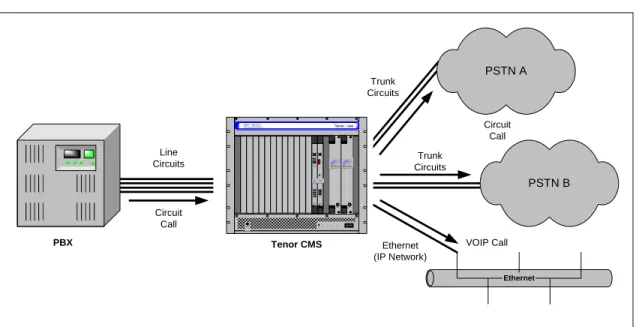
Line Circuit Originated Calls
Calls coming from a Line Circuit may be switched to either the data network as a VoIP call or to a Trunk Cir-cuit typically for connection to another cirCir-cuit switched network such as the PSTN. The routing decision made by the Tenor CMS is based upon your configuration and the dialed number.
Figure 1-2
Line Circuit Call Routing
Line Circuits Ethernet PSTN B Trunk Circuits Trunk Circuits PSTN A Ethernet (IP Network) Tenor CMS PBX VOIP Call Circuit Call Circuit Call 01 Reset+ 3.3V+5V+12V-12V QUINTUM TECHNOLOGIES, INC. TM QUINTUM TECHNOLOGIES, INC. TM TM Fault Fault TM Ground Strap Statu s Alarm C PUPCI Reset 10/100 Ethe rnet Link TX/RX 12 34 QUINTUMTM TECHNOLOGIES,INC. Hot Swap CPU Hot Swap DS1 St at us Alarm 12 PCI CPU B ank DSP 12 TX/RX Link 1 2 3 4 5 6 7 8 10/100 Ethernet Span Status TECHNOLOGIES,INC. QUINTUMTM
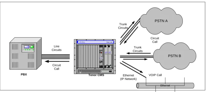
Trunk Circuit Originated Calls
A call coming from a Trunk Circuit may be switched to either the data network as a VoIP call, a Line Circuit, or trunk typically for connection to a termination device on the users premises such as a PBX. The routing decision made by the Tenor CMS is based upon your configuration and the dialed number.
Figure 1-3
Trunk Circuit Call Routing
Intra-trunk Routing - “Hairpinning”
As a result of intra-trunk routing, incoming calls from a particular Trunk Circuit are switched by Tenor CMS to be routed back out the same trunk circuit routing group.
Figure 1-4
Intra-Trunk Routing
Line Circuits Ethernet PSTN B Trunk Circuits Trunk Circuits PSTN A Ethernet (IP Network) Tenor CMS PBX VOIP Call Circuit Call Circuit Call 01 Reset+ 3.3V+5V+12V-12V QUINTUM TECHNOLOGIES, INC. TM QUINTUM TECHNOLOGIES, INC. TM TM Fault Fault TM Ground Strap Statu s Alarm C PUPCI Reset 10/100 Ethe rnet Link TX/RX 12 34 QUINTUMTM TECHNOLOGIES,INC. Hot Swap CPU Hot Swap DS1 St at us Alarm 12 PCI CPU B ank DSP1 2TX/RX Link 1 2 3 4 5 6 7 8 10/100 Ethernet Span Status TECHNOLOGIES,INC. QUINTUMTM Line Circuits Ethernet PSTN B Trunk Circuits Trunk Circuits PSTN A Ethernet (IP Network) Tenor CMS PBX VOIP Call Circuit Call Circuit Call 01 Reset+3.3V+ 5V+12V-12V QUINTUM T ECHNOLOGIES, INC. TM QUINTUM TECHNOLOGIES, INC. T M T M Fault Fault TM Ground Strap Status Alarm CPUPCI Reset 10/100 Ethernet Link TX/RX 123 4 QUINTUMTM TECHNOLOGIES,INC. H ot SwapCPU H ot SwapDS1 St atus Alarm 12 PCI CPU Bank DSP 12 TX/RX Link 1 2 3 4 5 6 7 8 10/100 Ethernet Span Status TECHNOLOGIES,INC. QUINTUMT M
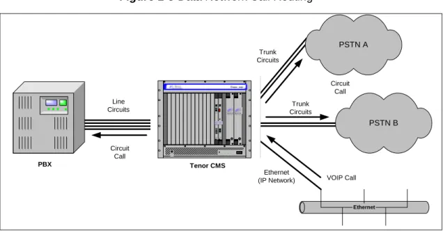
Data Network Calls
Calls coming from the data network can be routed to the Line circuit or Trunk circuit spans. The Tenor CMS will route calls based upon the dialed number. If the number is configured as a local phone number, the call will be sent to a Line circuit for termination, otherwise the call is considered a “Hop-Off call” and the Tenor CMS sends it out through a Trunk circuit span, typically connected to the PSTN.
Figure 1-5
Data Network Call Routing
Other Call Routing Options
There are several routing tables you can configure via the Command Line Interface (CLI) to adjust how the Tenor CMS unit routes specific calls. For example, you may want to configure 911 as a “bypass number”, which means that all 911 calls coming into Tenor CMS from the line circuit will be routed directly to a Trunk circuit presumably connected to a PSTN. Bypass calls are never routed over IP.
There are four types of routing databases you can configure: Bypass Directory Numbers (BPN), Local Direc-tory Numbers (LDN), Hop-Off DirecDirec-tory Numbers (HDN) and Static Route. Bypass DirecDirec-tory Numbers are directly routed from a Line circuit to a Trunk circuit. Local Directory Numbers are phone numbers that are reachable through local Line Circuits. Hop-Off Directory Numbers are phone numbers that can be routed over the IP to another Tenor location and then out to the Trunk circuit, possibly to the PSTN as a local call. Static Routes are used between networks and other H.323 devices that are not registered to the network through the Border Element (such as non-Quintum gateways).
Line Circuits Ethernet PSTN B Trunk Circuits Trunk Circuits PSTN A Ethernet (IP Network) Tenor CMS PBX VOIP Call Circuit Call Circuit Call 01 Reset+3.3V+5V+12V- 12V QUINTUM T ECHNOLOGIES, INC. T M QUINTUM TECHNOLOGIES, INC. TM TM Fault Fault TM Ground Strap St atus Alarm CPUPCI Reset 10/100 Ethernet Link T X/RX 12 34 QUINTUMTM TECHNOLOGIES,INC. H ot Swap CPU H ot Swap DS1 St at us Alarm 12 PCI CPU Bank DSP 1 2L inkT X/RX 1 2 3 4 5 6 7 8 10/100 Ethernet Span Status TECHNOLOGIES,INC. QUINTUMTM
Hop-off PBX Call
Hop-off numbers are phone number patterns for calls to be routed out trunks. They are entered in a HopoffNumberDirectory and associated with TrunkCircuitRoutingGroups that govern the trunks where matching calls should be sent.
Tenor CMS supports those Hop-off PBX calls where the destination Tenor CMS is programmed to route the call to the PSTN via Trunk Circuit. (A Hop-off PBX call is a toll call which hops through a private network to reduce or eliminate the toll charge.) The destination Tenor CMS unit is configured with the phone numbers to be “supported” for this feature.
SNMP Support
The Tenor CMS unit supports Simple Network Management Protocol (SNMP), the standard protocol used to exchange network information between different types of networks.
Call Detail Recording
Through the Call Detail Record (CDR) feature, the Tenor CMS may generate a call record at the completion of each call, typically for accounting purposes. A CDR is a string of data that contains call information such as call date and time, call duration, calling party, and called party. Tenor CMS may store call detail records locally or they can be sent to a CDR server within the network. The CDR contains sufficient information to capture billing data, which can be used to create billing reports by third party billing software.
H.323 Gatekeeper Services
Gatekeeper
A Gatekeeper in an H.323 network provides call control services and other services to H.323 endpoints (i.e., gateways, terminals, and MCUs). The Tenor CMS has a built-in H.323 gatekeeper which complies to the H.323 industry specifications for voice control and management. The gatekeeper performs call routing func-tions for calls entering and exiting a site.
The Gatekeeper performs IP call routing functions, such as call control signaling and call authorization for Gateways, IP phones, and H.323 terminals. The Gatekeeper communicates with other Gatekeepers through a Border Element. When using a group of Tenor CMS units, you can assign one unit as the Gatekeeper for the network. We recommend you configure each CMS as its own gatekeeper.
Tenor CMS supports gatekeeper to gatekeeper communication using LRQ (Location Request) messaging scheme.
Zone Management
A zone is a group of H.323 defined endpoints controlled by a Gatekeeper. Endpoints can be gateways (i.e., Tenor CMS), terminals, and/or multipoint conferencing units (MCUs). Endpoints establish control channels with a gatekeeper for registration, admission, security, and call routing information about the endpoint is sent to the gatekeeper, including: IP address, unit type (gateway, terminal, or MCU) and routing information (such as phone numbers, number patterns, etc.).
A collection of zones is an administrative domain. An administrative domain provides call routing services for its zones through gatekeeper to gatekeeper messages or gatekeeper to border element messages (see Border Element” for more information).
Call Registration
H.323 endpoints in the same zone register with the designated gatekeeper. When registration is complete and a call is originated, the call request is sent to the gatekeeper. The call request provides the Gatekeeper with the dialed number and requests the routing information. The gatekeeper confirms the dialed number and supplies the endpoint with the destination IP address. For example, a Tenor CMS’s gatekeeper will act as the gate-keeper for that zone and all of the other endpoints will register with it.
Border Element
The Tenor CMS’s gatekeeper uses a border element to gain access to the routing database of the administrative domain for the purpose of call completion or any other services that involve communications with other end-points out of the administrative domain. The border element functionality is built into the Tenor CMS unit,
In addition, if you are using more than one CMS unit, you can configure one of the border elements for that zone. The Tenor CMS unit provides two border elements: primary and secondary. These work together as one entity to provide redundancy and fault tolerance; there are no hierarchical differences.
Call Services
Gatekeepers provide services such as addressing, authorization and authentication of terminals and gateways, bandwidth management, accounting, billing, and charging. Gatekeepers also provide call-routing services. Specifically, the Tenor CMS Gatekeeper provides the functions which follow:
Address Translation. The gatekeeper translates telephone numbers into IP addresses and vice versa. It per-forms Alias Address (phone number) to Transport Address (IP address) translation when an endpoint requests service. The Gatekeeper uses a translation table to translate an Alias Address (an address such as an H.323 identifier that a user may not understand) to a transport address. The translation table is updated using Regis-tration messages.
Autodiscovery. The gatekeeper is discovered in one of the following ways: An endpoint sends an IP broad-cast called a Gatekeeper Request message (GRQ) message (which includes that correct gatekeeper name) to discover a Gatekeeper OR the endpoint will discover a gatekeeper by its IP address.
Routing. The gatekeeper identifies the IP address of endpoints in its administrative domain. The gatekeeper builds a routing database from information obtained from the border element and also from gateways and H.323 endpoints.
Admissions Control. All H.323 endpoints must register and request permission to enter the gatekeeper’s zone; the gatekeeper will confirm or deny access to the network.The gatekeeper authorizes network access and protects the integrity of the network using Admissions Request (ARQ), Admissions Confirmation (ACF) and Admissions Reject (ARJ) messages.
Border Element Gatekeeper Zone Gatekeeper Zone Gatekeeper Zone Administrative Domain Border Element Gatekeeper Zone Gatekeeper Zone Gatekeeper Zone Administrative Domain
SIP User Agent
SIP (Session Initiation Protocol) is a signaling protocol used to establish a session on an IP network
for voice control and management; it is a request-response protocol that closely resembles
Hyper-text Transfer Protocol (HTTP), which forms the basis of the World Wide Web. SIP re-uses many of
the constructs and concepts of Internet protocols such as HTTP and Simple Mail Transfer Protocol
(SMTP). The purpose of SIP is only to establish/change/terminate sessions. SIP is not concerned
with the content or details of the session.
SIP is Transport layer-independent, which means it can be used with any transport protocol: UDP,
TCP, ATM, etc. It is text-based, so it requires no encoding/decoding like H.323. And SIP supports
user mobility, using proxies and redirecting requests to your current location.
When configured for SIP the Tenor will act as a SIP User Agent (Endpoint) as defined in IETF
RFC3261. Multiple user agents allow for separate agents to be allocated to each SIP call. It will be
able to gateway calls to and from the IP network, and Customer Premise Equipment (CPE) such as
phones, PBX's, and FAX machines, or the Public Switched Telephone Network (PSTN). The Tenor
SIP User Agent will work in conjunction with an external SIP proxy or redirect server to route and
connect calls oer SIP based networks.
There are three basic components of SIP:
1. User Agent (Endpoint)
•
client element, initiates calls
•
server element, answers calls
2. Network Server (Proxy Server or Redirect Server)
•
name resolution
•
user location
•
redirect and forking
3. Registrar
C
hapter 2: Hardware Components
This chapter tells you what is contained in your hardware package. A description of each component is also included.
Specifically, the following topics are covered:
!
Chassis!
Power Supplies!
WAN CardsHardware Description
Tenor CMS is available in CMS (14 slot), CMS960 (8 slot), and a CMS240 (2 slot).
The CMS (14 slot), CMS960 (8 slot), and CMS240 (2 slot) provide network connection and functionality through WAN cards, DSP resource cards, and a system controller card/CPU card. Communication through the chassis backplane is achieved through the following: packet bus and TDM bus. The packet bus is used for car-rying packet-oriented data and the TDM bus is used for transporting circuit switched PCM traffic.
For the AC unit, the front side of the chassis provides access to WAN cards (T1/E1/DS1), power supplies, the system controller card/CPU card, and DSP card; the rear side exposes the back portion of the transition cards for network connection as well as power cord connection.
For the DC unit, the front side of the chassis provides access to WAN cards (T1/E1/DS1), DSP cards, the sys-tem controller/CPU card and power supplies. The rear side exposes the back portion of the transition cards for network connections, as well as the circuit breakers, power receptacles and power plugs.
Through all of these units, you can connect up to four different points: Line Circuit (PBX), Trunk Circuit (PSTN), Data network (Ethernet LAN) and a PC.
Board interoperability
Certain boards are supported in certain releases; the chart which follows lists which boards are supported according to CMS release.
Table 2-1
Board supported according to CMS Release
Board Type
Release
P1.3.x
Release
P1.4.x and
higher
Release
P1.5.x
Release
P2.4.x
Release
P2.5.x
T1 Card Yes Yes Yes No Yes
E1 Card Yes Yes Yes No Yes
DS1 Card (with DSP module)
No Yes Yes Yes Yes
DSP Card Yes No Yes No No
System Controller Card Yes Yes Yes No No
Chassis - CMS (14 Slot)
The chassis is the 19” rack-mountable unit which houses all WAN cards, System Controller/CPU cards, DSP cards, and power supplies. The two system fans are installed at the top of the chassis. See the following sec-tions for unit front and unit back details; both the AC version and DC versions are illustrated and explained.
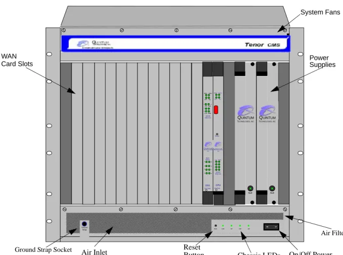
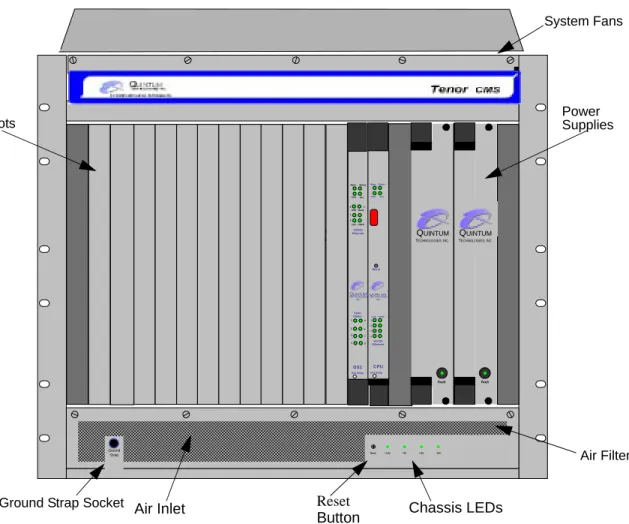
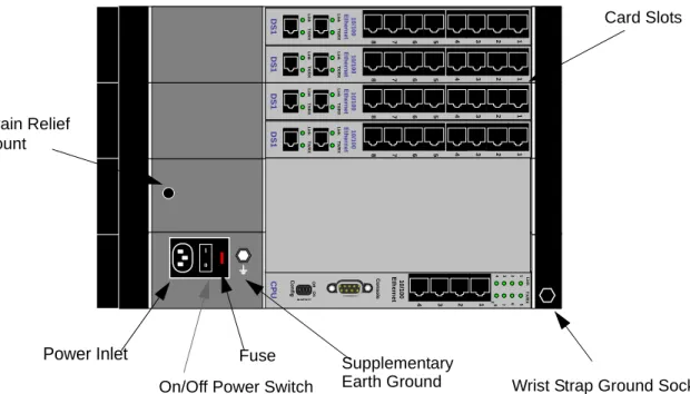
Front (with AC power)
NOTE: For pictorial purposes, Figure 2-1 shows the unit with 1 DS1 card and the CPU card.
Figure 2-1
Tenor CMS Front View - AC unit
• Card Slots. Fourteen slots are available for WAN cards, DSP Resource Cards, DS1 cards, and the CPU/ System Controller Card.
• Power Supplies. Two load-sharing AC power supplies. The load sharing feature enables one power sup-ply to take over if the other fails.
• System Fans. Two system fans, accessible through a swing down panel via thumb screws are used to cool the chassis. These fans are “hot-swappable”, meaning you can remove/replace the fans while the unit is operational.
• Reset Button. Enables you to reset the system. This function will be supported in a future release. • Ground Strap Socket. A ground connection is provided for ESD protection.
0 1 Reset +3.3V +5V +12V -12V QUINTUM TECHNOLOGIES, INC. TM QUINTUM TECHNOLOGIES, INC. TM TM Fault Fault TM Ground Strap Status Alarm CPUPCI Reset 10/100 Ethernet Link TX/RX 1 2 3 4 QUINTUMTM TECHNOLOGIES, INC. Hot Swap CPU Hot Swap DS1 Status Alarm 1 2 PCI CPU Bank DSP 1 2 TX/RX Link 1 2 3 4 5 6 7 8 10/100 Ethernet Span Status TECHNOLOGIES, INC. QUINTUMTM
Ground Strap Socket Air Inlet Reset
Button Chassis LEDs On/Off Power
System Fans
WAN Power
Supplies Card Slots
• Air Filter. The Air Filter is accessible by opening the lower front panel. You do not have to turn off the chassis. For cleaning, see Chapter 7: Diagnostics/Maintenance.
• Chassis LEDs. The LEDs are indicators as to the status of the four DC outputs of the power supplies. When these are lit, they indicate the respective voltages are being output from the power supplies. When unlit, the voltage is not being supplied. See Chapter 7: Diagnostics/Maintenance for more information.
• On/Off Power: A switch to turn power on and off.
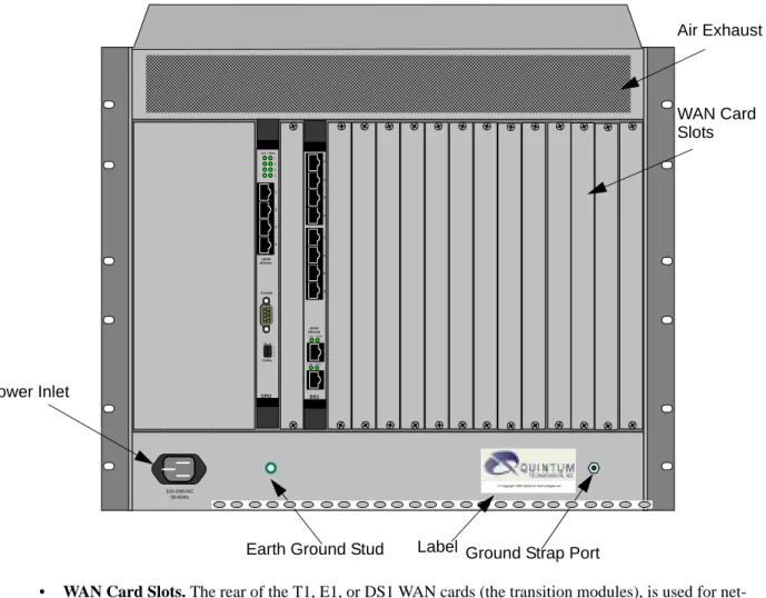
Rear (with AC power)
NOTE: For pictorial purposes, Figure 2-2 is shown with 2 DS1 cards and the CPU Card.
Figure 2-2
Tenor CMS Rear View - AC unit
A M P 10 100-240VAC 50-60Hz
© Copyright 2001 Quintum Technologies Inc.
1 2 3 4 DS1 1 2 3 4 10/100 Ethernet Link TX/RX Link TX/RX 1 2 3 4 Console Config 1 2 3 4 10/100 Ethernet Link TX/RX 1 2 3 4 CPU OffOn Air Exhaust Power Inlet
Ground Strap Port Earth Ground Stud Label
WAN Card Slots
Front (with DC Power)
NOTE: For pictorial purposes, Figure 2-3 shows the unit with 1 DS1 card and the CPU card.
Figure 2-3
Tenor CMS Front View - DC unit
• Card Slots. Fourteen slots are available for WAN cards (T1/E1/DS1), DSP cards, and the CPU/System Controller card.
• Power Supplies. Two load-sharing DC power supplies. The load sharing feature enables one power sup-ply to take over if the other fails.
• System Fans. Two system fans, accessible through a swing down panel via thumb screws, are used to cool the chassis. These fans are “hot-swappable”, meaning you can remove/replace the fans while the unit is operational.
• Reset Button. Enables you to reset the system. This function will be supported in a future release. • Ground Strap Socket. A ground connection is provided for ESD protection.
• Air Filter. The Air Filter is accessible by opening the lower front panel. You do not have to turn off the chassis. For cleaning, see Chapter 7: Diagnostics/Maintenance.
• Chassis LEDs. The LEDs are indicators as to the status of the four voltage supplies. When these are lit, they indicate the respective voltages are being output from the power supplies. When unlit, the voltage is not being supplied. See Chapter 7: Diagnostics/Maintenance for more information.
0 1 Reset +3.3V +5V +12V -12V QUINTUM TECHNOLOGIES, INC. TM QUINTUM TECHNOLOGIES, INC. TM TM Fault Fault TM Ground Strap Status Alarm CPUPCI Reset 10/100 Ethernet Link TX/RX 1 2 3 4 QUINTUM TM TECHNOLOGIES, INC. Hot Swap CPU Hot Swap DS1 Status Alarm 1 2 PCI CPU Bank DSP 1 2 TX/RX Link 1 2 3 4 5 6 7 8 10/100 Ethernet Span Status TECHNOLOGIES, INC. QUINTUMTM
Ground Strap Socket Air Inlet Reset
Button Chassis LEDs
System Fans
Power Supplies Card Slots
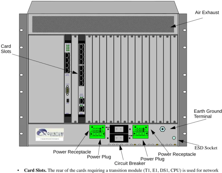
Rear (with DC power)
NOTE: For pictorial purposes, Figure 2-4 is shown with 1 DS1 card and the CPU card.
Figure 2-4
Tenor CMS Rear View - DC unit
• Card Slots. The rear of the cards requiring a transition module (T1, E1, DS1, CPU) is used for network connection. The quantity will vary depending upon the number of cards you have inserted.
• Power Plug. Provides wire connections to the -42 to -60 VDC power from the DC feed(s) to the power receptacles. Both may be used, but only one is required (one must have the power connected to its power inlet connector).
• Power Receptacle. Power inlet receives DC power from the power plug.
10 1 2 3 4 DS1 1 2 3 4 10/100 Ethernet Link TX/RX Link TX/RX 1 2 3 4 Console Config 1 2 3 4 10/100 Ethernet Link TX/RX 1 2 3 4 CPU OffOn Off On 0 1 Off On 0 1 © Copyright 2001 Quintum Technologies Inc.
-48 |RTN| -48 |RTN| -48 |RTN| -48 |RTN| Air Exhaust Card Earth Ground Terminal ESD Socket Power Plug
Power Receptacle Power Receptacle
Power Plug Circuit Breaker
Chassis - CMS960 (8 Slot)
The chassis is a 19” rack-mountable unit which houses all WAN cards, System Controller/CPU cards, DSP cards, and power supplies. See the following sections for unit front and unit back details; both the AC version and DC versions are illustrated and explained. The slots are 1-8; the bottom slot being slot number 1.
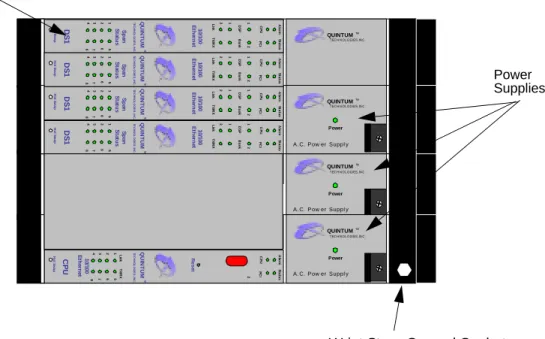
Front (with AC power)
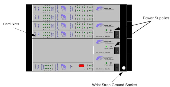
NOTE: For illustration purposes, Figure 2-5 shows the unit with 4 DS1 cards and the CPU card.
Figure 2-5
Tenor CMS960 Front View - AC unit
• Card Slots. Eight slots are available for WAN cards, DSP Resource Cards, DS1 cards, and the CPU/ System Controller Card.
• Power Supplies. Three load-sharing AC power supplies; two are installed in the unit. Power supplies act in a load sharing manner. Two power supplies are standard, the third power supply is optional, and ensures redundancy if any one of the three fail.
• Wrist Strap Ground Socket. Socket available in which to connect an ESD wrist strap for ESD protec-tion.
Power Supplies Card Slots
A.C. Power Supply Power QUINTUM TEC H N O L OG IES, IN C . TM QUINTUM TEC H N O L OG IES, IN C . TM TE CHNO L O G IE S , I NC. QU IN T U M TM Ho t S w a p DS 1 Sp an St a tu s 4 8 3 7 26 15 10/ 100 Et h e rn et DS P Li nk Al a rm CP U 1 1 2 2 Ba n k TX /R X St a tu s PC I
A.C. Power Supply Power QUINTUM TEC H N O L OG IES, IN C . TM TE CHNO L O G IE S , I NC. QU IN T U M TM CP U 4 8 3 7 26 15 Al a rm CP U 2 St a tu s PC I R ese t 10 /1 00 Et h e rn et Li nk TX /R X Ho t S w a p
A.C. Power Supply Power QUINTUM TEC H N O L OG IES, IN C . TM TE CHNO L O G IE S , I NC. QU IN T U M TM Ho t S w a p DS 1 Sp an St at u s 4 8 3 7 26 15 1 0 /100 Et h e rn e t DS P Li nk Al a rm CP U 1 1 2 2 Ba n k TX /R X St a tu s PC I TE CHNO L O G IE S , I NC. QU IN T U M TM Ho t S w a p DS 1 Sp a n St a tu s 4 8 3 7 26 15 10/ 100 Et h e rn et DS P Li nk Ala rm CP U 1 1 2 2 Ba n k TX /R X St a tu s PC I TE CHNO L O G IE S , I NC. QU IN T U M TM Ho t S w a p DS 1 Sp an St a tu s 4 8 3 7 26 15 10/ 10 0 Et h e rn e t DS P Li nk Al a rm CP U 1 1 2 2 Ba n k TX /R X St a tu s PC I
Rear (with AC power)
NOTE: For illustration purposes, Figure 2-6 is shown with 4 DS1 cards and the CPU card.
Figure 2-6
Tenor CMS960 Rear View - AC unit
• Card Slots. Eight slots are available for WAN cards, DSP Resource Cards, DS1 cards, and the CPU/ System Controller Card.
• Power Inlet. Inlet for which you insert the supplied AC power cord. The unit requires 110-240 VAC.
• On/Off Power: A switch to turn power on and off.
• Strain Relief Mount. The Strain Relief Mount enables you to connect the power cord strain relief to the unit. A power cord strain relief is a plastic device designed to avoid accidental power down of the Tenor CMS (i.e., if the power cord is accidentally pulled, the strain relief will relieve pressure put on the cord.) • Fuse. Replaceable fuse. See Chapter 8: Diagnostics/Maintenance for more information.
• Supplementary Earth Ground. A supplementary earth ground connection is provided.
• Wrist Strap Ground Socket. Socket available in which to connect an ESD wrist strap for ESD protec-tion. Power Inlet CP U 2 4 8 3 7 26 15 TX /R X 1 2 3 4 Li nk C onf ig 1 2 3 4 Of f On C ons ole 10/ 10 0 Et h e rn et 1 0 10/ 10 0 Et h e rn et 1 2 3 4 5 6 7 8 DS 1 Li nk TX /R X Li nk TX /R X 10 /1 0 0 Et h e rn e t 8 7 6 5 4 3 2 1 DS 1 Li n k TX /R X Li n k TX /R X 10 /1 0 0 Et h e rn e t 8 7 6 5 4 3 2 1 DS 1 Li nk TX /R X Li nk TX /R X 10/ 10 0 Et h e rn et 1 2 3 4 5 6 7 8 DS 1 Li nk TX /R X Li nk TX /R X
On/Off Power Switch Fuse
Card Slots
Strain Relief Mount
Supplementary
Front (with DC Power)
NOTE: For illustration purposes, Figure 2-7 shows the unit with 4 DS1 cards and the CPU card.
Figure 2-7
Tenor CMS960 Front View - DC unit
• Card Slots. Eight slots are available for WAN cards (T1/E1/DS1), DSP cards, and the CPU/System Controller card.
• Power Supplies. Three load-sharing AC power supplies; two are installed in the unit. Power supplies act in a load sharing manner. Two power supplies are standard, the third power supply is optional, and ensures redundancy if any one of the three fail.
• Wrist Strap Ground Socket. Socket available in which to connect an ESD wrist strap for ESD protec-tion. Card Slots D.C. Power Supply Power Alarm QUINTUM TEC H N O L OG IES, IN C . TM QUINTUM TEC H N O L OG IES, IN C . TM T E CHNO L O G IE S , I N C. QU IN T U M TM Ho t S w a p DS 1 Sp an St at u s 4 8 3 7 26 15 1 0 /100 Et h e rn e t DS P Li nk Al a rm CP U 1 1 2 2 Ba n k TX /R X St a tus PC I D.C. Power Supply Power Alarm QUINTUM TEC H N O L OG IES, IN C . TM T E CHNO L O G IE S , I NC. QU IN T U M TM CP U 4 8 3 7 26 15 Al a rm CP U 2 St a tus PC I R e set 10/ 100 Et h e rn et Li nk TX /R X Ho t S w a p D.C. Power Supply Power Alarm QUINTUM TEC H N O L OG IES, IN C . TM T E C HNO L O G IE S , I N C. QU IN T U M TM Ho t S w a p DS 1 Sp a n St a tu s 4 8 3 7 26 15 10/ 10 0 Et h e rn e t DS P Li nk Al a rm CP U 1 1 2 2 Ba n k TX /R X St a tus PC I T E CHNO L O G IE S , I NC. QU IN T U M TM Ho t S w a p DS 1 Sp a n St a tu s 4 8 3 7 26 15 10/ 100 Et h e rn et DS P Li nk Ala rm CP U 1 1 2 2 Ba n k TX /R X St a tus PC I TE CHNO L O G IE S , I NC. QU IN T U M TM Ho t S w a p DS 1 Sp a n St at u s 4 8 3 7 26 15 1 0 /100 Et h e rn e t DS P Li n k Al a rm CP U 1 1 2 2 Ba n k TX /R X St a tus PC I Power Supplies
Rear (with DC power)
CAUTION: This equipment is designed to permit the connection of the earthed conductor of the d.c. supply circuit to the earthing conductor at the equipment. See installation instructions.
Figure 2-8
Tenor CMS960 Rear View - DC unit
• Card Slots. The rear of the cards requiring a transition module (T1, E1, DS1, CPU) is used for network connection. The quantity will vary depending upon the number of cards you have inserted.
• Strain Relief Mount. The Strain Relief Mount enables you to connect the power cord strain relief to the unit. A power cord strain relief is a plastic device designed to avoid accidental power down of the Tenor CMS (i.e., if the power cord is accidentally pulled, the strain relief will relieve pressure put on the cord.) • Power Terminal. Provides screw terminal wire connections to the -40 to -60 VDC power.
• Supplementary Earth Ground. A supplementary earth ground connection is provided.
• Circuit Breaker. There is one circuit breaker for each power connection; lettering on each one indicates which breaker controls which power receptacle connection. When you push the rocker to ON, the breaker will be closed (a red indicator shows the user that the contacts are closed). When you push the rocker to OFF, the contacts will open. To ensure all power is disconnected from unit, open both circuit breakers.
• Wrist Strap Ground Socket. Socket available in which to connect an ESD wrist strap for ESD
protec-CP U 2 4 8 3 7 26 15 TX /R X 1 2 3 4 Li nk C onf ig 1 2 3 4 Of f O n C ons ol e 10/ 100 Et h e rn e t 10/ 100 Et h e rn e t 8 7 6 5 4 3 2 1 DS 1 Li nk TX /R X Li nk TX /R X 10/ 100 Et h e rn e t 8 7 6 5 4 3 2 1 DS 1 Li nk TX /R X Li nk TX /R X 10/ 100 Et h e rn e t 4 3 2 1 5 6 7 8 DS 1 Li nk TX /R X Li nk TX /R X 10/ 1 00 Et h e rn e t 4 3 2 1 5 6 7 8 DS 1 Li nk TX /R X Li nk TX /R X On 1Off0 On 1Off0 -48 RTN -48 RTN A B Power Terminal Circuit Breaker Card Slots Supplementary
Chassis- CMS240 (2 slot)
The 2 slot chassis is a 19” rack-mountable unit which houses all WAN cards, System Controller/CPU cards, DSP cards, and a power supply. See the following sections for unit front and unit back details; both the AC version and DC versions are illustrated and explained. There are two slots, the bottom slot is slot number 1 and contains the CPU card.
Front View (with AC power)
Figure 2-9
Tenor CMS240 Front View - DC unit
• Card Slots. Two slots are available for WAN cards (T1/E1/DS1), DSP cards, and the CPU/System Con-troller card.
• Power Supply. One AC Power Supply.
• Wrist Strap Ground Socket. Socket available in which to connect an ESD wrist strap for ESD protec-tion.
A.C. Power Supply
Power QUINTUM TEC H N O L O G IES, IN C . TM T E C H N O L OGI E S , I N C . QU IN T U M TM Ho t S w a p DS 1 Sp a n St a tu s 4 8 3 7 26 15 10/ 1 00 Et h e rn et DS P Li n k Al a rm CP U 1 1 2 2 Ba n k TX /R X St a tu s PC I T E CHNO L O G IE S , I NC. QU IN T U M TM CP U 4 8 3 7 26 15 Al a rm CP U 2 St a tu s PC I Re s e t 10/ 1 00 Et h e rn e t Li nk TX /R X Ho t S w a p
Power Supply Wrist Strap
Ground Socket
Rear View (with AC power)
Figure 2-10
Tenor CMS240 Rear View - AC unit
• Strain Relief Mount. The Strain Relief Mount enables you to connect the power cord strain relief to the unit. A power cord strain relief is a plastic device designed to avoid accidental power down of the Tenor CMS (i.e., if the power cord is accidentally pulled, the strain relief will relieve pressure put on the cord). • Power Inlet. Inlet for which you insert the supplied AC power cord. The unit requires 110-240 VAC. • On/Off Power Switch. A switch to turn power on and off.
• Fuse. Replaceable fuse. See Chapter 8: Diagnostics/Maintenance for more information. • Supplementary Earth Ground. A supplementary earth ground connection is provided.
• Card Slots. The rear of the cards requiring a transition module (T1, E1, DS1, CPU) is used for network connection. The quantity will vary depending upon the number of cards you have inserted.
• Wrist Strap Ground Socket. Socket available in which to connect an ESD wrist strap for ESD protec-tion. 10/ 100 Et h e rn e t 8 7 6 5 4 3 2 1 DS 1 Li nk TX/ R X Li nk TX/ R X CP U 2 4 8 3 7 26 15 TX /R X 1 2 3 4 Li n k Co n fig 1 2 3 4 Of f On C ons ol e 10/ 100 Et h e rn et 1 0 Power Inlet
On/Off Power Switch
Supplementary Earth Ground Strain Relief Mount Fuse
Card Slots
Front view (with DC power)
Figure 2-11
Tenor CMS240 Front View - DC unit
• Card Slots. Two slots are available for WAN cards (T1/E1/DS1), DSP cards, and the CPU/System Con-troller card.
• Power Supply. One DC Power Supply.
• Wrist Strap Ground Socket. Socket available in which to connect an ESD wrist strap for ESD protec-tion. D.C. Power Supply Power Alarm QUINTUM TEC H N O L O G IES, IN C . TM T E C HNO L O G IE S , I N C. QU IN T U M TM Ho t S w a p DS 1 Sp a n St a tu s 4 8 3 7 26 15 10/ 1 00 Et h e rn et DS P Li n k Al a rm CP U 1 1 2 2 Ba n k TX /R X St a tu s PC I T E CHNO L O G IE S , I NC. QU IN T U M TM CP U 4 8 3 7 26 15 Al a rm CP U 2 St a tu s PC I Re s e t 10/ 1 00 Et h e rn e t Li nk TX /R X Ho t S w a p Power Supply
Card Slots
Wrist StrapGround Socket
Rear View (with DC power)
“CAUTION: This equipment is designed to permit the connection of the earthed conductor of the d.c. supply circuit to the earthing conductor at the equipment. See installation instructions.”
Figure 2-12
Tenor CMS Rear View - DC unit
• Circuit Breaker. There is one circuit breaker for each power connection; lettering on each one indicates which breaker controls which power receptacle connection. When you push the rocker to ON, the breaker will be closed (a red indicator shows the user that the contacts are closed). When you push the rocker to OFF, the contacts will open. To ensure all power is disconnected from unit, open both circuit breakers.
• Strain Relief Mount. The Strain Relief Mount enables you to connect the power cord strain relief to the unit. A power cord strain relief is a plastic device designed to avoid accidental power down of the Tenor CMS (i.e., if the power cord is accidentally pulled, the strain relief will relieve pressure put on the cord.) • Power Terminal. Provides screw terminal wire connections to the -40 to -60 VDC power.
• Supplementary Earth Ground. A supplementary earth ground connection is provided.
• Card Slots. The rear of the cards requiring a transition module (T1, E1, DS1, CPU) is used for network connection. The quantity will vary depending upon the number of cards you have inserted.
• Wrist Strap Ground Socket. Socket available in which to connect an ESD wrist strap for ESD protec-tion. 10/ 1 00 Et h e rn e t 4 3 2 1 5 6 7 8 DS 1 Li n k TX /R X Li n k TX /R X CP U 2 4 8 3 7 26 15 TX /R X 1 2 3 4 Li nk Co n fig 1 2 3 4 Of f O n C o ns ol e 10 /1 00 Et h e rn e t On 1 Off 0 -48 RTN
Strain Relief Mount Supplementary Earth Ground Power Terminal
Circuit Breaker
System Controller Card (Available for CMS P1.5.x )
The System Controller card is a single slot Compact PCI (Peripheral Component Interconnect) card which provides the central management functionality for the Tenor CMS unit. The controller card is the call routing engine for the system and coordinates all activity within the chassis, including system resources management/ monitoring.
The system controller card provides an interface for transferring VoIP data throughout the system and commu-nicating with other network cards via PCI bus.
As the central point of system resource management, the system controller card implements the intelligent call routing and IP call signaling. The card also acts as an interface through which the user is able to perform net-work and system management functions. The system controller card is always inserted in slot 14 for the CMS (the slot nearest the power supplies, identified with a red card guide). See Figure 2-13.
Figure 2-13
System Controller Card
10/100 Base-T Ethernet port. This port provides one RJ-45 jack for connection to a 10/100 BASE-T Ether-net LAN switch or hub via RJ-45 cable. The input/output signals are listed in Table 2-2.
Console ABT BFL CPU CPCI PCI .2 9 5 .5 3 1 TM RST 10/100
Ethernet 10/100 Ethernet Port
Console Port Reset
Abort
Figure 2-14
10/100 Ethernet Port Pin order
Table 2-2
Input/Output Signals for 10/100 Ethernet Port
Pin # Signal Definition Color
1 TX + Transmit Data White w/orange
2 TX - Transmit Data Orange
3 RX + Receive Data White w/green
4 RSVD Reserved Blue
5 RSVD Reserved White w/blue
6 RX - Receive Data Green
7 RSVD Reserved White w/Brown
Console port. This RS-232 connector is used for connection to a PC’s serial port via DB-9 null modem cable at 38400 BPS 8N1, and no flow control. The input/output signals are listed in Table 2-3.
Figure 2-15
DB-9 Female Connector Pin Order
Table 2-3
Serial Null Modem Cable DB-9 Connector Pinouts
RST. Resets the System Controller board along with the entire chassis.
ABT. Abort recessed push button switch used for internal Quintum use only.
LEDs. LEDs provide a high level indication of the system controller card activity. Basic definitions follow. See Chapter 7: Diagnostics/Maintenance for a detailed description for troubleshooting purposes.
• BFL. Steady yellow light indicates the board has failed. • CPU. Green light indicates the CPU bus is active. • PCI. Green light indicates that the local PCI bus is busy.
• CPCI. Green light indicates the Compact PCI (CPCI) bus is busy.
Pin #
Function
Description
1 RSVD Reserved 2 RXD Receive Data 3 TXD Transmit Data 4 RSVD Reserved 5 GND Signal Ground 6 RSVD Reserved 7 RSVD Reserved 8 RSVD Reserved 9 RSVD Reserved