Feature Interaction Detection Contest
5
thInternational Workshop on Feature Interactions
Instructions
Contest committee: Nancy Griffeth (chair), Ralph Blumenthal , Jean-Charles
Gregoire, and Tadashi Ohta
The goal of this contest is to compare different feature interaction detection tools according to a single benchmark collection of features. We have tried to describe the features both precisely and simply. This has not been easy, but we hope that the result will be adequate to the purpose.
The original contest announcement is attached in Appendix A. The feature definitions, in the form of Chisel sequence diagrams, are in Appendix B.
In order to define the features, we model a network as a collection of black boxes (Section 1),
communicating with each other via defined interfaces (Section 2). We define the POTS service and the features as sequences of events taking place on these interfaces (Section 3).
The choice of features has been dictated by the need for them to interact. They must have some
commonality. For this first contest, we are using versions of familiar POTS features, to ensure that there are plenty of interactions. To provide a bit of a challenge for the tools, we introduce features in several different categories. There are billing features as well as call control features, and some features are switch-based whereas others are implemented on an IN platform.
Don’t assume that because these are familiar features, the interactions will be the usual ones. The features are defined on a simplified network model, their definitions have been changed slightly, and – most important – we have sincerely tried to define each feature without thinking about the other features. Each feature was defined as if it is the only feature that will be used and as if it will be active on only one call at a time. As a result, the interactions may be quite different from the expected ones! In particular, beware of interactions that are normally so embedded in the features that they appear to be part of them.
Our models of POTS, IN, and billing are quite simple. We hope that more detailed models of these will be available for future contests. However, for this first contest, it seemed important to keep things simple as is reasonable (and no simpler). In future contests, we would also like to see themes involving ISDN, wireless, PCS, and even the Web.
1. The Network
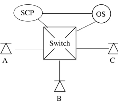
The network consists of:
• End-user equipment (telephones)
• A switch (fast enough to handle all telephones at once)
• A Service Control Point (SCP) that processes IN features like credit card calling, 800/900 numbers, IN Call Forwarding, and so on
• An Operations System (OS) that does billing
Switch
SCP OS
A C
B
Figure 1. Diagram of the network
2. Events on the Network Interfaces
The network interfaces are the interface between the user and the switch (on which the telephone is used for signaling); the interface between the switch and the SCP (on which IN messages are used); and the interface to the billing system (for tracking the beginning and end of each call).
2.1 User/Switch
The telephone provides the events on the interface between the user and the switch. The tables below summarize the events between the user and the switch. The format of an event is:
<event> <parameter>:<type> … <parameter>:<type>
where <event> is an event name, <parameter> is a symbol, and <type> indicates the type of the parameter. We use types Address (for a telephone number), Cadence (for a special ring or tone), and Message (for a string).
User to Switch Switch to User
Off-hook X:Address DialTone X:Address [C:Cadence]
On-hook X:Address Start AudibleRinging X:Address Y:Address Dial X:Address Y:Address Start Ringing X:Address Y: Address [C:Cadence]
Flash X:Address Start CallWaitingTone X: Address Y: Address [C:Cadence] Stop AudibleRinging X:Address Y:Address
Stop Ringing X:Address Y:Address
Stop CallWaitingTone X:Address Y:Address LineBusyTone X: Address [C:Cadence] Announce X:Address M:Message Disconnect X:Address Y:Address Display X:Address M:Message
The first parameter of an event is the address of the telephone on whose interface the event occurs. A number of events have more parameters:
• Dial A B means that the subscriber at address A dials the address B.
• Flash A is equivalent to an On-hook A followed by an Off-hook A, unless a feature uses it otherwise. We assume that end-users have a Flash button.
• DialTone A n means that dialtone occurs at address A. The second parameter, if present, specifies a special cadence for the dialtone. We provide stop and start events for ringing and call-waiting tone, but for the given features, no interesting events occur between starting and stopping DialTone or LineBusyTone, so we left them as single events.
• Start Ringing A B n and Start CallWaitingTone A B n mean that alerting starts at address A for a call originated at address B. If the third parameter is present, it specifies the cadence of the alerting. It not, the cadence is the usual cadence.
• Start AudibleRinging A B means that the ringback tone is provided at address A while waiting for the user at address B to answer the call.
• Stop Ringing A B, Stop CallWaitingTone A B, and Stop AudibleRinging A B mean to stop the ringing or tone occurring at address A in relation to a call to or from B.
• LineBusyTone A n means that the telephone to which A is attempting a connection is busy. The second parameter, if present, specifies the cadence of the tone.
• Announce A M means that announcement M is played to address A.
• Disconnect A B informs A that B has disconnected a connection with A. (We use a restricted definition for Disconnect. It is a signal from the switch to a user, signaling the user that a connected party has gone On-hook. The On-hook event is the signal from the user to the switch that the user is disconnecting.)
• Display A M uses a display screen on telephone at address A (or a Caller ID box at the same address) to display the message M concerning the current call. Typically, the message is the number of the calling party, but it could be another string such as “Anonymous.”
We assume that the various cadences and messages have well-defined implementations, but we will just use descriptive strings to distinguish them.
2.2 Switch/SCP
The Bellcore AIN document GR-1298-CORE has been a reference for this interface, but we use a much simplified version of the message parameters. A trigger message includes only the trigger name, the subscriber address, the calling party address, the called party address, and the time. The response messages include only the response type, the subscriber name, the calling party address, and other necessary parameters for that response type.
Switch to SCP SCP to Switch
Trigger N:TriggerName S:Address A:Address B:Address T:Time
Response R:ResponseType S:Address A:Address … (see below)
Resource S:Address A:Address M:Message
The type TriggerName is an enumeration of the names of IN triggers. Some valid TriggerName’s are ORIGINATION_ATTEMPT, INFO_COLLECTED, INFO_ANALYZED, and NETWORK_BUSY. In the trigger message, the first address parameter is that of the subscriber, the second of the calling party, the third of the called party, and the last parameter is the current time.
The type ResponseType is an enumeration of the SCP responses to trigger messages. Some valid ResponseType’s are ANALYZE_ROUTE, CONTINUE, FORWARD_CALL, and
SEND_TO_RESOURCE.
The Resource S A M message responds to the SEND_TO_RESOURCE message. The string M is a string of collected digits.
Additional parameters (after the subscriber and calling party addresses) for the ResponseTypes are given in the following table.
Response Type Additional Parameters
ANALYZE_ROUTE B:Address C:Address FORWARD_CALL B:Address C:Address
CONTINUE B:Address
SEND_TO_RESOURCE M:Message DISCONNECT
ANALYZE_ROUTE S A B C means to route a call from A to B with C as the paying party (normally, C will be A). S is the subscriber on whose behalf the trigger was activated, usually A or B.
FORWARD CALL S A B C means to forward a call to C, originated by A, with terminating address B. CONTINUE S A B means to continue processing the call as if no trigger had occurred.
SEND_TO_RESOURCE S A M means to play the message M at address A and collect the response (if any).
DISCONNECT S A means to terminate processing of calls from A until after A has gone on-hook.
2.3 Interface to the billing system
We assume the existence of a billing system recognizing messages from the switch or the SCP and that billing is based entirely on subscriber addresses and calls placed. These messages provide the time, the calling party, called party, and (LogBegin only) the paying party.
to OS
LogBegin X:Address Y:Address P:Address T:Time LogEnd X:Address Y:Address T:Time
2.4 Simplifying Assumptions
1. The above messages are all there are.
2. User to Switch “messages” get an instantaneous response from the switch, i.e., DialTone starts immediately after Off-hook and stops immediately after Dial. This means that two user messages won’t be sent one immediately after the other; there will always be a switch response between. 3. On-hook is instantaneously followed by Disconnect. There is no extended disconnect timing. 4. There are no network busy conditions.
5. There is no provisioning or provisioning of features. Also, there is no feature activation or de-activation. A subscriber either has a feature or doesn’t.
6. The end-user equipment has a button for Flash.
3. Services and Features
We define POTS and all features of POTS as sets of sequences of events on interfaces between network elements (telephones, switch, SCP, and OS). The definitions are expressed in the form of Chisel sequence diagrams. A Chisel sequence diagram is just a directed graph, whose nodes are events on the various interfaces. The diagram defines a set of event sequences for a single call, one for each path through the graph. Event sequences involving multiple calls can be interleaved to define global system activity.
3.1 Interpreting the Chisel sequence diagram for POTS
For illustration, a basic two-party POTS diagram is given at the beginning of the Appendix. It includes both telephones in a two-party call, and also some messages for the billing system.
A node (one of the ovals) in a sequence diagram contains a number, which uniquely identifies the node within the feature, and one or more events and variable assignments. The nodes are connected by directed edges (arrows in the diagrams). Multiple events in a node are separated by vertical bars (|||). A node containing multiple such events is equivalent to the sequence diagram representing any possible sequence of those same events (i.e., A ||| B means {AB, BA}; A ||| B ||| C means {ABC, ACB, BAC, BCA, CAB, CBA}; and so forth).
Variables are used in conditions on the edges, to define when an edge can be followed in constructing an event sequence from the diagram and to restrict possible interleavings of event sequences. A variable defines one or more sequences of events, in the sense that Busy B defines the set of event sequences having one of the following properties:
• An event sequence containing an Off-hook B not followed by On-hook B.
• An event sequence containing Ringing B not followed by Disconnect B A.
Variables may be conceptually part of a feature but we don’t have any expectation that they will be implemented (or not).
A condition next to an edge means that to continue an event sequence by following that edge, the
condition must be true at the end of the event sequence. C syntax is used in the conditions (~ for not, && for and, || for or).
We use two techniques to define the value of a variable after an event. First, at the beginning of a feature definition, we provide some rules about the values of the variables (to minimize the complexity of the diagram). Second, especially for variables introduced for the individual features, we include an assignment statement with an event to say that the variable takes on a new value after the event. The format of this is <event> / <var> <- <value>.
Consider the POTS diagram at the beginning of the Appendix. In this POTS diagram, we describe the values of several variables – Busy A, Ringing A B, and AudibleRinging A B – in rules at the top of the page. Because they are already defined in the rules, we don’t really need to set the values of any variables in this diagram, but for illustration we set the values for Busy B in nodes 4, 9, 10, and 14.
The POTS diagram represents only two telephones and a single call. To use a sequence to determine all possible event sequences representing a single call, substitute all pairs of telephone addresses for A and B (and any other symbols). Let’s use O(a) to designate the set of all such sequences with originating telephone a. Multiple calls can be originated at a, so let U(a) be the set of all sequences derived by concatenating any number of sequences of O(a) (U(a) = O(a)*, the Kleene closure of O(A)). Then, to determine all possible sequences of events in the network, we can interleave the sets U(A), over all possible call originators A, in all ways allowed by the conditions on the edges.
3.2 Interpreting sequence diagrams for features
Each feature provides some modification to POTS, thereby redefining the subscribed service for that subscriber. We don’t model service provisioning or activation, so if a subscriber has a service, that service is always active.
The POTS diagram represents a single call, originated by party A. The feature diagrams represent modifications to this POTS diagram – subdiagrams that can be “pasted” into the POTS diagram at given points. To specify where a feature can be pasted in, we need to designate the node in the POTS diagram and the relationship of the symbols A and B in the POTS diagram to the symbols used in the feature diagram. The designation of a node in the POTS diagram looks like: POTS A<-X B<-Y n, meaning use
node n from the POTS sequence diagram with X substituted for A and Y substituted for B. If either X or Y is “any,” then any telephone address is possible there.
A root feature node (i.e., a node with no parents) will be a child of a POTS node. The designation of the POTS node goes above an arrow leading into the node. If the feature node replaces one of the children of this POTS node, the designation of that child goes inside the feature node. Otherwise, the feature node is an additional child of the POTS node.
A leaf feature node (i.e., a node with no children) will be a parent of one or more POTS nodes. The designation of each POTS node goes below an arrow leading out of the leaf feature node.
For illustration, see Figure 1 in the Appendix, which is the sequence diagram for Call Forwarding/Busy Line. Each sequence in the CFBL diagram starts with A dialing (i.e., it will follow a sequence in which the last event was DialTone A) and ends with A and C idle (i.e., both A and C are on-hook and neither is ringing – the next event, if taken from the POTS sequence diagram, would be an off-hook or a ringing event).
4. Variables
The following variables are used in the sequence diagrams.
Busy A: true between an Off-hook A event and the next On-hook A event or between a Start Ringing A event and the next Stop Ringing A event.
Other variables are:
Ringing A B: true between a Start Ringing A event immediately following a Dial B A event and the next Stop Ringing A event
AudibleRinging A B: true between a Start AudibleRinging A event immediately following a Dial A B event and the next Stop AudibleRinging A event.
Note that Busy is true for a telephone if any of the other variables are. We also use Idle A to mean that Busy A is not true.
Additional variables may be introduced by a features. Most often, these “variables” define feature parameters (e.g., addresses of screened telephones or PIN’s for charging calls), and are fixed for each subscriber (but different for different subscribers). For variables that change during a call, the convention is to describe how the variable behaves with the unfeatured POTS service, in terms of sequences of events (as above), and then to include changes in the value of the feature in the sequence diagram. For the above variables, to keep the diagrams as simple as possible, we will not usually show each change of value. However, if a feature affects the value of one of them (as Call Waiting and Three-Way Calling do the value of Busy), the changes will be shown in the sequence diagram.
5. The Phase 1 Features
5.1 Call Forwarding Busy Line
With the Call Forwarding Busy Line feature, all calls to the subscribing line are redirected to a
predetermined number when the line is busy. The subscriber pays any charges for the forwarded call from his station to the new destination. The subscriber’s originating service is not affected.
5.2 Calling Number Delivery
Calling Number Delivery (CND) is a feature that allows the called telephone to receive a calling party’s Directory Number (DN) and the date and time. In the on-hook state, in a real network, the delivery of this information occurs during the long silent interval between the first and second power ringing cycles. For the purposes of the contest, we assume the capability of delivering the number, and deliver it whenever an idle called party receives the Ringing event.
Sequence Diagram: Figure 2, Appendix
5.3 IN Freephone Billing
The INFreephone feature allows the subscriber to pay for incoming calls. Call routing is normally part of this feature, but we define that in the next feature.
Sequence Diagram: Figure 3, Appendix
5.4 IN Freephone Routing
The IN Freephone feature allows the subscriber to redirect a call to various telephones, potentially using the all or part of calling number and/or the time of day.
Sequence Diagram: Figure 4, Appendix.
5.5 IN Teen Line
Teen Line restricts outgoing calls based on the time of day (i.e., hours when homework should be the primary activity). This can be overridden on a per-call basis by anyone with the proper identity code. We describe this as an IN feature.
Sequence Diagram: Figure 5, Appendix
5.6 Terminating Call Screening
Terminating call screening (TCS) restricts incoming calls. Calls from lines that appear on a screening list are redirected to a vague but polite message.
Sequence Diagram: Figure 6, Appendix
5.7 Three-way Calling
Three-way calling allows the connection of three parties in a single conversation.
Sequence Diagram: Figure 7, Appendix.
5.8 IN Call Forwarding
The Call forwarding (CF) feature permits the subscriber to have incoming calls redirected to another number, no matter what the called party line status is. The user’s originating service is unaffected, even for charging. We describe this as an IN service.
5.9 Call Waiting
The Call waiting (CW) feature allows the subscriber to be notified that another party is trying to reach his number while her line is busy, and to accept the new call by placing the original call on hold. Subsequently, the subscriber can switch back and forth between the calls.
Sequence Diagram: Figure 9, Appendix
5.10 Charge Call
The Charge Call feature allows a caller to be automatically charged on a different telephone number than the calling number. The feature is invoked by dialing a code (as defined in the sequence diagram, a prefix “0” to the called telephone number. The caller is then prompted to dial the telephone number to be charged and a PIN. If the PIN is correct, the caller can proceed with the call.
Appendix A. Contest Announcement
FEATURE INTERACTION DETECTION TOOL CONTESTA feature interaction detection contest will be held in association with the 5th Feature Interaction Workshop ’98, with the goal of providing a simple comparison of different automated tools for feature interaction detection.
Eligibility: Any automated tool for detecting feature interactions may be entered, as long as it was not developed by a contest committee member, a current student of a contest committee member, or a current manager or immediate subordinate of a contest committee member. Contestants are encouraged to submit papers describing their tools to the workshop, but they are not required to.
Evaluation of tools: The tools will be evaluated according to:
1) The coverage of the tool (that is, how many of the features did the contestant actually define in the tool language?).
2) The number of valid feature interactions found.
Conduct of contest: There will be two phases to the contest. Phase one, from February 15 to July 15, will involve the ten features defined below. In phase two, you will have two more weeks, from July 16 to July 31, to find the interactions with two more features.
No list of the interactions will be supplied. In each phase, contestants will submit a list of interactions and the sequence of events in which each interaction occurs. The results for phase one must be submitted by July 15, 1998, and for phase two by July 31, 1998. Please send your results by email to
[email protected] or snail mail to: Nancy Griffeth
600 Mountain Avenue MH 2C-308A
Murray Hill, NJ 07974 USA
Appendix B. Feature Definitions
Notation
Events consist of event names followed by parameters. Multiple events separated by ||| can occur in any order.
A node of a sequence diagram contains a number, which uniquely identifies the node within the service or feature, followed by one or more events (separated by |||). An event may be followed by a “/” and a variable assignment.
Rules for variable values may be given at the beginning of a sequence diagram or the variable values may be determined by assignments in the nodes in the diagram.
An expression involving one or more variables and appearing next to an edge should be interpreted as a logical expression that must evaluate “True” when that edge is followed in the sequence diagram. We begin each diagram with a brief text description of the feature it specifies. Then we define any variables introduced for that feature. Finally, we give rules specifying the sets of sequences that end with that variable “True”.