© 2001 by CRC Press LLC
15
Flight Management
Systems
15.1 Introduction 15.2 FundamentalsNavigation • Flight Planning • Trajectory Predictions • Performance Computations • Guidance • Auto Flight Phase Transitions
15.3 Summary
15.1 Introduction
The flight management system typically consists of two units, a computer unit and a control display unit. The computer unit can be a standalone unit providing both the computing platform and various interfaces to other avionics or it can be integrated as a function on a hardware platform such as an Integrated Modular Avionics cabinet (IMA). The Control Display Unit (CDU or MCDU) provides the primary human/machine interface for data entry and information display. Since hardware and interface imple-mentations of flight management systems can vary substantially, this discussion will focus on the functional aspects of the flight management system.
The flight management system provides the primary navigation, flight planning, and optimized route determination and en route guidance for the aircraft and is typically comprised of the following interrelated functions: navigation, flight planning, trajectory prediction, performance computations, and guidance.
To accomplish these functions the flight management system must interface with several other avionics systems. As mentioned above, the implementations of these interfaces can vary widely depending upon the vintage of equipment on the aircraft but generally will fall into the following generic categories.
• Navigation sensors and radios • Inertial/attitude reference systems • Navigation radios
• Air data systems • Displays
• Primary flight and navigation • Multifunction
• Engine
• Flight control system • Engine and fuel system • Data link system • Surveillance systems
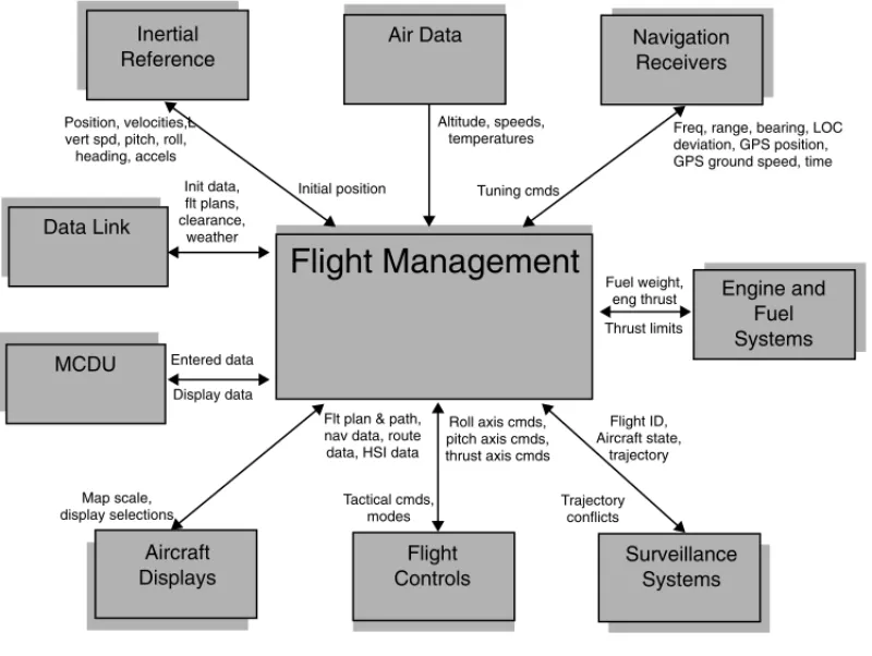
Figure 15.1 depicts a typical interface block diagram. Randy Walter
Today, flight management systems can vary significantly in levels of capability because of the various aviation markets they are intended to serve. These range from simple point to point lateral navigators to the more sophisticated multisensor navigation, optimized four-dimensional flight planning/guidance systems. The flight management system in its simplest form will slowly diminish as reduced separation airspace standards place more demands on the aircraft’s ability to manage its trajectory more accurately, even though lateral-only navigators will continue to have a place in recreational general aviation.
With its current role in the aircraft, the flight management system becomes a primary player in the current and future CNS/ATM environment. Navigation within RNP airspace, data-linked clearances and weather, aircraft trajectory-based traffic management, time navigation for aircraft flow control, and seam-less low-visibility approach guidance all are enabled through advanced flight management functionality.
15.2 Fundamentals
At the center of the FMS functionality is the flight plan construction and subsequent construction of the four-dimensional aircraft trajectory defined by the specified flight plan legs and constraints and the aircraft performance. Flight plan and trajectory prediction work together to produce the four-dimensional tra-jectory and consolidate all the relevant tratra-jectory information into a flight plan/profile buffer. The navigation function provides the dynamic current aircraft state to the other functions. The vertical, lateral steering, and performance advisory functions use the current aircraft state from navigation and the information in the flight plan/profile buffer to provide guidance, reference, and advisory information relative to the defined trajectory and aircraft state.
• The navigation function — responsible for determining the best estimate of the current state of the aircraft.
• The flight planning function — allows the crew to establish a specific routing for the aircraft. FIGURE 15.1 Typical interface block diagram.
Flight Management
Altitude, speeds,temperatures
Initial position Tuning cmds
Freq, range, bearing, LOC deviation, GPS position, GPS ground speed, time
Navigation Receivers Data Link MCDU Aircraft Displays Flight Controls Surveillance Systems Engine and Fuel Systems Air Data Position, velocities,Ł vert spd, pitch, roll,
heading, accels Init data, flt plans, clearance, weather Entered data Display data Map scale, display selections
Flt plan & path, nav data, route data, HSI data
Tactical cmds, modes Roll axis cmds, pitch axis cmds, thrust axis cmds Trajectory conflicts Flight ID, Aircraft state, trajectory Fuel weight, eng thrust Thrust limits Inertial Reference
• The trajectory prediction function — responsible for computing the predicted aircraft profile along the entire specified routing.
• The performance function — provides the crew with aircraft unique performance information such as takeoff speeds, altitude capability, and profile optimization advisories.
• The guidance functions — responsible for producing commands to guide the aircraft along both the lateral and vertical computed profiles.
Depending on the particular implementation, the ancillary I/O, BITE, and control display functions may be included as well. Since the ancillary functions can vary significantly, this discussion will focus on the core flight management functions.
There are typically two loadable databases that support the core flight management functions. These are the navigation database which must be updated on a monthly cycle and the performance database that only gets updated if there’s been a change in the aircraft performance characteristics (i.e., engine variants or structural variants affecting the drag of the aircraft).
The navigation database contains published data relating to airports, navaids, named waypoints, airways and terminal area procedures along with RNP values specified for the associated airspace. The purpose of the navigation data base is twofold. It provides the navigation function location, frequency, elevation, and class information for the various ground-based radio navigation systems. This information is necessary to select, auto-tune, and process the data from the navigation radios (distance, bearing, or path deviation) into an aircraft position. It also provides the flight plan function with airport, airport-specific arrival, departure, and approach procedures (predefined strings of terminal area waypoints), airways (predefined enroute waypoint strings), and named waypoint information that allows for rapid route construction. A detailed description of the actual data content and format can be found in ARINC 424.
The performance database contains aircraft/engine model data consisting of drag, thrust, fuel flow, speed/altitude envelope, thrust limits, and a variety of optimized and tactical speed schedules that are unique to the aircraft. Figure 15.2 shows the interrelationships between the core functions and the databases.
15.2.1 Navigation
The navigation function within the FMS computes the aircraft current state (generally WGS-84 geodetic coordinates) based on a statistical blending of multisensor position and velocity data. The aircraft current FIGURE 15.2 Flight management functional block diagram.
Navigation (acft current state)
Navigation Data Base Flight Planning Performance Computations Lateral
Guidance Perf Data
Base Trajectory Prediction Lateral & Vertical Profile Flight Plan Buffer Vertical Guidance Data Link Data Entry (performance advisories) (lateral cmds) (vertical cmds) (intended flt path)
state data usually consists of:
• Three-dimensional position (latitude, longitude, altitude) • Velocity vector
• Altitude rate
• Track angle, heading, and drift angle • Wind vector
• Estimated Position Uncertainty (EPU) • Time
The navigation function is designed to operate with various combinations of autonomous sensors and navigation receivers. The position update information from the navigation receivers is used to calibrate the position and velocity data from the autonomous sensors, in effect providing an error model for the autonomous sensors. This error model allows for navigation coasting based on the autonomous sensors while maintaining a very slow growth in the EPU. If the updating from navigation aids such as DME, VOR, or GPS is temporarily interrupted, navigation accuracy is reasonably maintained, resulting in seamless operations. This capability becomes very important for operational uses such as RNAV approach guidance where the coasting capability allows completion of the approach even if a primary updating source such as GPS is lost once the approach is commenced. A typical navigation sensor complement consist of:
• Autonomous sensors • Inertial reference • Air data • Navigation receivers • DME receivers • VOR/LOC receivers • GPS receivers
The use of several navigation data sources also allows cross-checks of raw navigation data to be performed to ensure the integrity of the FMS position solution.
15.2.1.1 Navigation Performance
The navigation function, to be RNP airspace compliant per DO-236, must compute an Estimated Position Uncertainty (EPU) that represents the 95% accuracy performance of the navigation solution. The EPU is computed based on the error characteristics of the particular sensors being used and the variance of the individual sensors position with respect to other sensors. The RNP for the airspace is defined as the minimum navigation performance required for operation within that airspace. It is specified by default values based on the flight phase retrieved from the navigation data base for selected flight legs or crew-entered in response to ATC-determined airspace usage. A warning is issued to the crew if the EPU grows larger than the RNP required for operation within the airspace. The table below shows the current default RNP values for the various airspace categories.
A pictorial depiction of the EPU computation is shown below for a VOR/VOR position solution. A similar representation could be drawn for other sensors.
Airspace Definition Default RNP
Oceanic — no VHF navaids within 200 nm
12.0 nm
Enroute — above 15,000 ft 2.0 nm
Terminal 1.0 nm
As can be seen from the diagram, the estimated position uncertainty (EPU) is dependent on the error characteristics of the particular navigation system being used as well as the geometric positioning of the navaids themselves. Other navigation sensors such as an inertial reference system have error characteristics that are time-dependent. More information pertaining to EPU and various navigation navaid system error characteristics can be found in RTCA DO-236.
15.2.1.2 Navigation Receiver Management
The various navigation receivers require different levels of FMS management to obtain a position update solution.
GPS — The GPS receiver is self-managing in that the FMS receives position, velocity, and time information without any particular FMS commands or processing. Typically, the FMS will provide an initial position interface to reduce the satellite acquire time of the receiver and some FMSs may provide an estimated time of arrival associated with a final approach fix waypoint to support the Predictive Receiver Autonomus Integrity Monitor (PRAIM) function in the GPS. More information on the GPS interface and function can be found in ARINC 743.
VHF navaids (DME/VOR/ILS) — The DME/VOR/ILS receivers must be tuned to an appropriate station to receive data. The crew may manually tune these receivers but the FMS navigation function will also auto-tune the receivers by selecting an appropriate set of stations from its stored navigation database and sending tuning commands to the receiver(s). The selection criteria for which stations to tune are
• Navaids specified within a selected flight plan procedure, while the procedure is active.
• The closest DME navaids to the current aircraft position of the proper altitude class that are within range (typically 200 nm).
• Collocated DME/VORs within reasonable range (typically 25 nm).
• ILS facilities if an ILS or LOC approach has been selected into the flight plan and is active. Since DMEs receive ranging data and VORs receive bearing data from the fixed station location, the stations must be paired to determine a position solution as shown below:
VOR Station Receivedbearings VOR Station
Estimated position VOR bearing error
characteristic Range from station 1 Range from station 2 Range from station Bearing from station Bearing from station 1 Bearing from station 2 DME/DME pair DME/VOR pair (collocated) VOR/VOR pair
The pairing of navaids to obtain a position fix is based on the best geometry to minimize the position uncertainty (minimize the portion of EPU caused by geometric dilution of precision, GDOP). As can be seen from the figure above, the FMS navigation must process range data from DMEs and bearing data from VORs to compute an estimated aircraft position. Further, since the DME receives slant range data from ground station to aircraft, the FMS must first correct the slant range data for station elevation and aircraft altitude to compute the actual ground-projected range used to determine position. The station position, elevation, declination, and class are all stored as part of the FMS navigation data base. There are variations in the station-tuning capabilities of DME receivers. A standard DME can only accept one tuning command at a time, an agility-capable DME can accept two tuning commands at a time, and a scanning DME can accept up to five tuning commands at a time. VOR receivers can only accept one tuning command at a time. An ILS or LOC receiver works somewhat differently in that it receives cross-track deviation information referenced to a known path into a ground station position. These facilities are utilized as landing aids and therefore are located near runways. The FMS navigation function processes the cross-track infor-mation to update the cross-track component of its estimated position. More inforinfor-mation about DME/VOR/ILS can be found in ARINC 709, 711, and 710, respectively.
15.2.2
Flight Planning
The basis of the FMC flight profile is the route that the aircraft is to fly from the departure airport to the destination airport. The FMS flight planning function provides for the assembly, modification, and activa-tion of this route data known as a flight plan. Route data are typically extracted from the FMC navigaactiva-tion data base and typically consists of a departure airport and runway, a standard instrument departure (SID) procedure, enroute waypoints and airways, a standard arrival (STAR) procedure, and an approach procedure with a specific destination runway. Often the destination arrival (or approach transition) and approach procedure are not selected until the destination terminal area control is contacted. Once the routing, along with any route constraints and performance selections, are established by the crew, the flight plan is assembled into a “buffer” that is utilized predominantly by the trajectory predictions in computing the lateral and vertical profile the aircraft is intended to fly from the departure airport to the destination airport. The selection of flight planning data is done by the crew through menu selections either on the MCDU or navigation display or by data link from the airline’s operational control. Facilities are also provided for the crew to define additional navigation/route data by means of a supplemental navigation data base. Some of the methods for the crew to create new fixes (waypoints) are listed below.
PBD Waypoints — Specified as bearing/distance off existing named waypoints, navaids, or airports.
PB/PB Waypoints — Specified as the intersections of bearings from two defined waypoints.
ATO Waypoints — Specified by an along-track offset (ATO) from an existing flight plan waypoint. The waypoint that is created is located at the distance entered and along the current flight plan path from the waypoint used as the fix. A positive distance results in a waypoint after the fix point in the flight plan while a negative distance results in a waypoint before the fix point.
Lat/Lon Waypoints — Specified by entering in the latitude/longitude coordinates of the desired way-point.
Lat/Lon Crossing Waypoints — Created by specifying a latitude or longitude. A waypoint will be created where the active flight plan crosses that latitude or longitude. Latitude or longitude increments can also be specified, in which case several waypoints are created where the flight plan crosses the specified increments of latitude or longitude.
Intersection of Airways — Created by specifying two airways. A waypoint will be created at the first point where the airways cross.
Fix Waypoints — Created by specifying a “fix” reference. Reference information includes creation of abeam waypoints and creation of waypoints where the intersections of a specified radial or distance from the “fix” intersects the current flight plan.
Runway Extension Waypoints — Created by specifying a distance from a given runway. The new waypoint will be located that distance from the runway threshold along the runway heading.
Abeam Waypoints — If a direct-to is performed, selection of abeam points results in waypoints being created at their abeam position on the direct-to path. Any waypoint information associated with the original waypoint is transferred to the newly created waypoints.
FIR/SUA Intersection Waypoints — Creates waypoints where the current flight plan crosses FIR bound-aries and Special Use Areas (SUA) that are stored in the navigation data base.
The forward field of view display system shows a presentation of the selected segments of the flight plan as the flight plan is being constructed and flown.
The crew can modify the flight plan at any time. The flight plan modification can come from crew selections or via data link from the airline operational communications or air traffic control in response to a tactical situation. An edit to the flight plan creates a modified (or temporary) version of the flight plan that is a copy of the active flight plan plus any accrued changes made to it. Trajectory predictions are performed on the modified flight plan with each edit and periodically updated, which allows the crew to evaluate the impact of the flight plan changes prior to acceptance. When the desired changes have been made to the crew’s satisfaction this modified flight plan is activated by the crew.
15.2.2.1 Flight Plan Construction
Flight plans are normally constructed by linking data stored in the navigation data base. The data may include any combination of the following items:
• SID/STAR/approach procedures • Airways
• Prestored company routes
• Fixes (en route waypoints, navaids, nondirectional beacons, terminal waypoints, airport reference points, runway thresholds)
• Crew-defined fixes (as referenced above)
These selections may be strung together using clearance language, by menu selection from the navigation data base, by specific edit actions, or data link.
Terminal area procedures (SIDs, STARs, and approaches) consist of a variety of special procedure legs and waypoints. Procedure legs are generally defined by a leg heading, course or track, and a leg termination type. The termination type can be specified in many ways such as an altitude, a distance, or intercept of another leg. More detail on the path construction for these leg types and terminators will be discussed in the trajectory predictions section. Refer to ARINC 424 specification for further detail about what data and format are contained in the NDB to represent these leg types and terminations.
AF DME Arc to a Fix CA Course to an Altitude CD Course to a Distance CF* Course to a Fix CI Course to an Intercept CR Course to Intercept a Radial DF* Direct to a Fix
FA* Course from Fix to Altitude FC Course from Fix to Distance FD Course from Fix to DME Distance FM Course from Fix to Manual Term HA* Hold to an Altitude
HF* Hold, Terminate at Fix after 1 Circuit
*These leg types are recommended in DO-236 as the set that produces consistent ground tracks and the only types that should be used within RNP airspace.
HM* Hold, Manual Termination IF* Initial Fix
PI Procedure Turn
RF* Constant Radius to a Fix TF* Track to Fix
VA Heading to Altitude VD Heading to Distance
VI Heading to Intercept next leg VM Heading to Manual Termination VR Heading to Intercept Radial
Many of these leg types and terminations have appeared because of the evolution of equipment and instrumentation available on the aircraft and do not lend themselves to producing repeatable, deterministic ground tracks. For example, the ground track for a heading to an altitude will not only be dependent on the current wind conditions but also the climb performance of each individual aircraft. One can readily see that to fly this sort of leg without an FMS, the crew would follow the specified heading using the compass until the specified altitude is achieved, as determined by the aircraft’s altimeter. Unfortunately, every aircraft will fly a different ground track and in some cases be unable to make a reasonable maneuver to capture the following leg. For the FMS, the termination of the leg is “floating” in that the lat/lon associated with the leg termination must be computed. These nondeterministic-type legs present problems for the air traffic separation concept of RNP airspace and for this reason RTCA DO-236 does not recommend the use of these legs in terminal area airspace, where they are frequently used today. These leg types also present added complexity in the FMS path construction algorithms since the path computation becomes a function of aircraft performance. With the advent of FMS and RNAV systems, in general, the need for non-deterministic legs simply disappears along with the problems and complexities associated with them. Waypoints may also be specified as either “flyover” or nonflyover”. A flyover waypoint is a waypoint whose lat/lon position must be flown over before the turn onto the next leg can be initiated whereas a nonflyover waypoint does not need to be overflown before beginning the turn onto the next leg. 15.2.2.2 Lateral Flight Planning
To meet the tactical and strategic flight planning requirements of today’s airspace, the flight planning function provides various ways to modify the flight plan at the crew’s discretion.
Direct-to — The crew can perform a direct-to to any fix. If the selected fix is a downtrack fix in the flight plan, then prior flight plan fixes are deleted from the flight plan. If the selected fix is not a downtrack fix in the flight plan, then a discontinuity is inserted after the fix and existing flight plan data are preserved.
Direct/intercept — The direct/intercept facility allows the crew to select any fixed waypoint as the active waypoint and to select the desired course into this waypoint. This function is equivalent to a direct-to except the inbound course to the specified fix may be specified by the crew. The inbound course may be specified by entering a course angle, or if the specified fix is a flight plan fix, the crew may also select the prior flight plan-specified course to the fix.
Holding pattern — Holding patterns may be created at any fix or at current position. All parameters for the holding pattern are editable including entry course, leg time/length, etc.
Fixes — Fixes may be inserted or deleted as desired. A duplicate waypoint page will automatically be displayed if there is more than one occurrence of the fix identifier in the navigation database. Duplicate fixes are arranged in order starting from the closest waypoint to the previous waypoint in the flight plan.
Procedures — Procedures (SIDs, STARs, and approaches including missed approach procedures) may be inserted or replaced as desired. If a procedure is selected to replace a procedure that is in the flight plan, the existing procedure is removed and replaced with the new selection.
Airway segments — Airway segments may be inserted as desired.
Missed approach procedures — The flight planning function also allows missed approach procedures to be included in the flight plan. These missed approach procedures can either come from the navigation database where the missed approach is part of a published procedure, in which case they will be automatically
included in the flight plan, or they can be manually constructed by entry through the MCDU. In either case, automatic guidance will be available upon activation of the missed approach.
Lateral offset — The crew can create a parallel flight plan by specifying a direction (left or right of path) and distance (up to 99 nm) and optionally selecting a start and/or end waypoint for the offset flight plan. The flight planning function constructs an offset flight plan, which may include transition legs to and from the offset path.
15.2.2.3 Vertical Flight Planning
Waypoints can have associated speed, altitude, and time constraints. A waypoint speed constraint is interpreted as a “cannot exceed” speed limit, which applies at the waypoint and all waypoints preceding the waypoint if the waypoint is in the climb phase, or all waypoints after it if the waypoint is in the descent phase. A waypoint altitude constraint can be of four types — “at,” “at or above,” “at or below,” or “between.” A waypoint time constraint can be of three types — “at,” “after,” “before,” “after” and “before” types are used for en route track-crossings and the “at” type is planned to be used for terminal area flow control.
Vertical flight planning consists of selection of speed, altitude, time constraints at waypoints (if required or desired), cruise altitude selection, aircraft weight, forecast winds, temperatures, and destination baro-metric pressure as well as altitude bands for planned use of aircraft anti-icing. A variety of optimized speed schedules for the various flight phases are typically available. Several aircraft performance-related crew selections may also be provided. All these selections affect the predicted aircraft trajectory and guidance. 15.2.2.4 Atmospheric Models
Part of the flight planning process is to specify forecast conditions for temperatures and winds that will be encountered during the flight. These forecast conditions help the FMS to refine the trajectory predic-tions to provide more accurate determination of ETAs, fuel burn, rates of climb/descent, and leg transition construction.
The wind model for the climb segment is typically based on an entered wind magnitude and direction at specified altitudes. The value at any altitude is interpolated between the specified altitudes to zero on the ground and merged with the current sensed wind. Wind models for use in the cruise segment usually allow for the entry of wind (magnitude and direction) for multiple altitudes at en route waypoints. Future implementation of en route winds may be via a data link of a geographical current wind grid database maintained on the ground. The method of computing winds between waypoints is accomplished by interpolating between entries or by propagating an entry forward until the next waypoint entry is encountered. Forecast winds are merged with current winds obtained from sensor data in a method which gives a heavier weighting to sensed winds close to the aircraft and converges to sensed winds as each waypoint-related forecast wind is sequenced. The wind model used for the descent segment is a set of altitudes with associated wind vector entered for different altitudes. The value at any altitude is interpolated from these values, and blended with the current sensed wind.
Forecast temperature used for extrapolating the temperature profile is based on the International Standard Atmosphere (ISA) with an offset (ISA deviation) obtained from pilot entries and/or the actual sensed temperature.
Forecast temperature 15 ISA dev0.00198 altitude altitude 36,089
Forecast temperature 56.5 altitude 36,089
Air pressure is also utilized in converting speed between calibrated airspeed, mach, and true airspeed.
(Pressure ratio)(10.0000068753 altitude)5.2561 altitude 36,089
(Pressure ratio)0.22336 e(4.8063 (36089altitude)/100,000)
15.2.3 Trajectory Predictions
Given the flight plan, the trajectory prediction function computes the predicted four-dimensional flight profile (both lateral and vertical) of the aircraft within the specified flight plan constraints and aircraft performance limitations, based on entered atmospheric data and the crew-selected modes of operation.
The lateral path and predicted fuel, time, distance, altitude, and speed are obtained for each point in the flight plan (waypoints as well as inserted vertical breakpoints such as speed change, cross-over, level off, T/C, T/D points). The flight profile is continuously updated to account for nonforecasted conditions and tactical diversions from the specified flight plan.
To simplify this discussion, the flight path trajectory is broken into two parts — the lateral profile (the flight profile as seen from overhead) and the vertical profile (the flight profile as seen from the side). However, the lateral path and vertical path are interdependent in that they are coupled to each other through the ground speed parameter. Since the speed schedules that are flown are typically constant CAS/mach speeds for climb and descent phases, the TAS (or ground speed) increases with altitude for the constant CAS portion and mildly decreases with altitude for the constant mach portion, as shown in the following equations.
The significance of the change in airspeed with altitude will become apparent in the construction of the lateral and vertical profile during ascending and descending flights as described in the next section. Further, since the basic energy balance equations used to compute the vertical profile use TAS, these speed conversion formulas are utilized to convert selected speed schedule values to true airspeed values.
15.2.3.1 Lateral Profile
Fundamentally, the lateral flight profile is the specified route (composed of procedure legs, waypoints, hold patterns, etc.), with all the turns and leg termination points computed by the FMS according to how the aircraft should fly them. The entire lateral path is defined in terms of straight segments and turn segments which begin and end at either fixed or floating geographical points. Computing these segments can be difficult because the turn transition distance and certain leg termination points are a function of predicted aircraft speed (as noted in the equations below), wind, and altitude, which, unfortunately, are dependent on how much distance is available to climb and descend. For example, the turn transition at a waypoint requires a different turn radius and therefore a different distance when computed with different speeds. The altitude (and therefore speed of the aircraft) that can be obtained at a waypoint is dependent upon how much distance is available to climb or desend. So, the interdependency between speed and leg distance presents a special problem in formulating a deterministic set of algorithms for computing the trajectory. This effect becomes significant for course changes greater than 45˚, with the largest effect for legs such as procedure turns which require a 180˚ turn maneuver.
Lateral turn construction is based on the required course change and the aircraft's predicted ground speed during the turn. If the maximum ground speed that the aircraft will acquire during the required course change is known, a turn can be constructed as follows:
Mach sqrt (1[ {[10.2(CAS/661.5)2]3.51}1)0.2861]
TAS 661.5machsqrt[ ]
CAS calibrated airspeed in knots TAS true airspeed in knots
atmospheric pressure ratio actual temperature ( S.L. std. temperature) atmospheric temperature ratio actual temperature ( S.L. std. temperature)
Turn Radius (ft) (GS2) (gtan) Turn Arclength (ft) CourseTurn Radius
GS maximum aircraft ground speed during the turn g acceleration due to gravity
For legs such as constant radius to a fix (RF) where the turn radius is specified, a different form of the equation is used to compute the nominal bank angle that must be used to perform the maneuver.
To determine the maximum aircraft ground speed during the turn the FMC must first compute the altitude at which the turn will take place, and then the aircraft’s planned speed based on the selected speed schedule and any applicable wind at that altitude. The desired bank angle required for a turn is predetermined based on a trade-off between passenger comfort and airspace required to perform a lateral maneuver.
The basis for the lateral profile construction is the leg and termination types mentioned in the flight plan section. There are four general leg types:
• Heading (V) — aircraft heading • Course (C) — fixed magnetic course
• Track (T) — computed great circle path (slowly changing course) • Arc (A or R) — an arc defined by a center (fix) and a radius There are six leg terminator types:
• Fix (F) — terminates at geographic location • Altitude (A) — terminates at a specific altitude
• Intercept next leg (I) — terminates where leg intercepts the next leg • Intercept radial (R) — terminates where leg intercepts a specific VOR radial
• Intercept distance (D or C) — terminates where leg intercepts a specific DME distance or distance from a fix
• Manual (M) — leg terminates with crew action
Not all terminator types can be used with all leg types. For example, a track leg can only be terminated by a fix since the definition of a track is the great circle path between two geographic locations (fixes). Likewise, arc legs are only terminated by a fix. In a general sense, heading and course legs can be graphically depicted in the same manner understanding that the difference in the computation is the drift angle (or aircraft yaw).
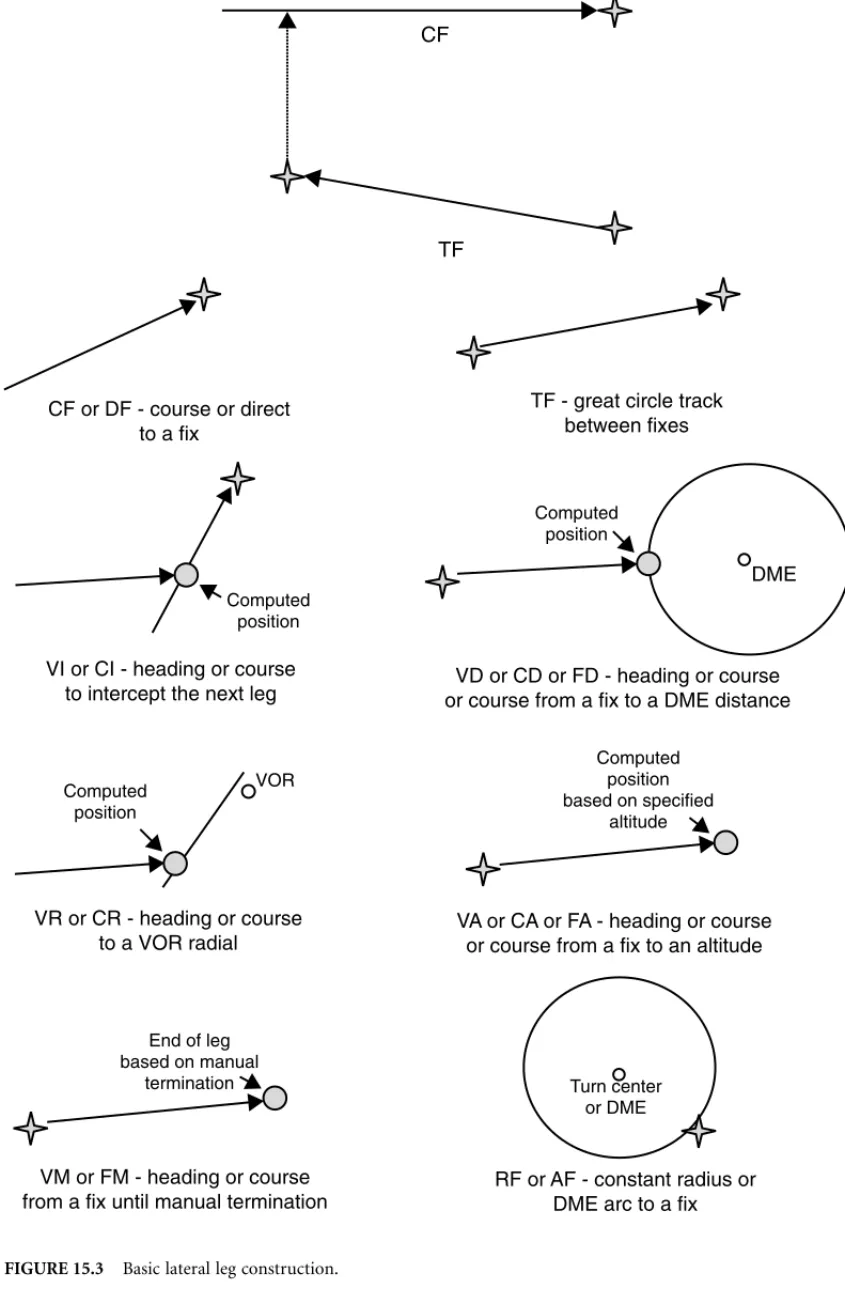
Figure 15.3 depicts a graphical construction for the various leg and terminator types. The basic construction is straightforward. The complexity arises from the possible leg combinations and formu-lating proper curved transition paths between them. For example, if a TF leg, is followed by a CF leg where the specified course to the fix does not pass through the terminating fix for the prior TF leg, then a transition path must be constructed to complete a continuous path between the legs.
In summary, the lateral flight path computed by the FMC contains much more data than straight lines connecting fixed waypoints. It is a complete prediction of the actual lateral path that the aircraft will fly under FMS control. The constructed lateral path is critical because the FMC will actually control the aircraft to it by monitoring cross-track error and track angle error, and issuing roll commands to the autopilot as appropriate.
15.2.3.2 Vertical Profile
The fundamental basis for the trajectory predictor is the numerical integration of the aircraft energy balance equations including variable weight, speed, and altitude. Several forms of the energy balance equation are used to accommodate unrestricted climb/descent, fixed gradient climb/descent, speed change, and level flight. The integration steps are constrained by flight plan-imposed altitude and speed restrictions as well as aircraft performance limitations such as speed and buffet limits, maximum altitudes,
FIGURE 15.3 Basic lateral leg construction.
CF
TF
CF or DF - course or direct to a fix
TF - great circle track between fixes
DME
VI or CI - heading or course
to intercept the next leg or course from a fix to a DME distanceVD or CD or FD - heading or course
VA or CA or FA - heading or course or course from a fix to an altitude VR or CR - heading or course
to a VOR radial
RF or AF - constant radius or DME arc to a fix VM or FM - heading or course
from a fix until manual termination
End of leg based on manual
termination Turn center
or DME Computed position based on specified altitude VOR Computed position Computed position Computed position
and thrust limits. The data that drives the energy balance equations come from the airframe/engine-dependent thrust, fuel flow, drag, and speed schedule models stored in the performance data base. Special construction problems are encountered for certain leg types such as an altitude-terminated leg because the terminator has a floating location. The location is dependent upon where the trajectory integration computes the termination of the leg. This also determines the starting point for the next leg.
The trajectory is predicted based on profile integration steps — the smaller the integration step the more accurate the computed trajectory. For each step the aircraft’s vertical speed, horizontal speed, distance traveled, time used, altitude change, and fuel burned is determined based on the projected aircraft target speed, wind, drag, and engine thrust for the required maneuver. The aircraft’s vertical state is computed for the end of the step and the next step is initialized with those values. Termination of an integration step can occur when a new maneuver type must be used due to encountering an altitude or speed constraint, flight phase change, or special segments such as turn transitions where finer integration steps may be prudent. The vertical profile is comprised of the following maneuver types: unrestricted ascending and descending segments, restricted ascending and descending segments, level segments, and speed change segments. Several forms of the energy balance equation are used depending on the maneuver type for a given segment of the vertical profile. Assumptions for the thrust parameter are maneuver type and flight phase dependent.
15.2.3.3 Maneuver Types
Unrestricted ascending and descending segments — The following form of the equation is typically used to compute the average vertical speed for fixed altitude steps (dh is set integration step). Using fixed altitude steps for this type of segment allows for deterministic step termination at altitude constraints. For ascending flight the thrust is general assumed to be the take-off, go-around, or climb thrust limit. For descending flight the thrust is generally assumed to be at or a little above flight idle.
where:
T Avg. thrust (lb)
D Avg. drag (lb)
GW A/C gross wt (lb) act Ambient temp (K)
Tstd Std. day temp (K)
Vave Average true airspeed (ft/sec)
g 32.174 ft/sec2
dVtrue Delta Vtrue (ft/sec)
dh Desired altitude step (ft)
The projected aircraft true airspeed is derived from the pilot-selected speed schedules and any appli-cable airport or waypoint-related speed restrictions. Drag is computed as a function of aircraft configu-ration, speed, and bank angle. Fuel flow and therefore weight change is a function of the engine thrust.
V S TD ( )Vave GW ---Tact Tstd --- Vave g --- dVtrue dh
Once V/S is computed for the step the other prediction parameters can be computed for the step.
Restricted ascending and descending segments — The following form of the equation is typically used to compute the average thrust for fixed altitude steps (dh and V/S are predetermined). Using fixed altitude steps for this type of segment allows for deterministic step termination at altitude constraints. The average V/S is either specified or computed based on a fixed flight path angle (FPA).
The fixed FPA can in turn be computed based on a point to point vertical flight path determined by altitude constraints, which is known as a geometric path. With a specified V/S or FPA segment the thrust required to fly this profile is computed.
The other predicted parameters are computed as stated for the unrestricted ascending and descending segment.
Level segments — Constant-speed-level segments are a special case of the above equation. Since and are by definition zero for level segments, the equation simplifies to TD. Level segments are typically integrated based on fixed time or distance steps so the other predicted parameters are computed as follows:
dt set integration step and
dsdt(Vtrue average along track wind for segment) ds delta distance for step
or
ds set integration step and
dtds(Vtrue average along track wind for segment) dt delta time for step
dwdt fuel flow(T) dw delta weight for step
Speed change segments — The following form of the equation is typically used for speed change segments to compute the average time for a fixed dVtrue step. The used is predetermined based on
ascending, descending, or level flight along with the operational characteristics of the flight controls or as for the case of geometric paths computed based on the required FPA. The thrust is assumed to be flight idle for descending flight, take-off or climb thrust limit for ascending flight, or cruise thrust limit for level flight.
dt dh
VS
---, where dt delta time for step
ds dt V( trueaverage along track wind for segment), where ds delta distance for step
dw dtfuel flow( )T , where dw delta weight for step
V Save GSavetanFPA, where GSave segment ground speed (ft/sec).
T WV Save Vave --- 1 Vave g ---dVtrue dh D dVtrue V Save V Save dt dVtrue g TD ( ) GW --- Tact Tstd ---V Save Vave --- dh V/Savedt
For all maneuver types the altitude rate, speed change, or thrust must be corrected for bank angle effects if the maneuver is performed during a turn transition. The vertical flight profile that the FMC computes along the lateral path is divided into three phases of flight: climb, cruise, and descent.
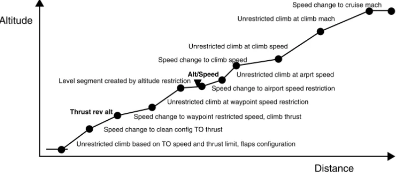
The climb phase — The climb phase vertical path, computed along the lateral path, is typically composed of the segments shown in Figure 15.4.
In addition to these climb segments, there can also be altitude level-off segments created by altitude restrictions at climb waypoints, and additional target speed acceleration segments created by speed restrictions at climb waypoints.
The cruise phase — The cruise phase vertical path, computed along the lateral path, is very simple. It’s typically composed of a climb speed to cruise speed acceleration or deceleration segment followed by a segment going to the FMC-computed top of descent. The cruise phase typically is predicted level at cruise altitude via several distance- or time-based integration steps. Unlike the climb and descent phase, the optimal cruise speeds slowly change with the changing weight of the aircraft, caused by fuel burn. If step climb or descents are required during the cruise phase, these are treated as unrestricted ascending flight and fixed V/S or FPA descents. At each step the FMC computes the aircraft’s path speed, along-path distance traveled, and fuel burned based on the projected aircraft target speed, wind, drag, and engine thrust. The projected aircraft true airspeed is derived from the pilot-selected cruise speed schedule and applicable airport-related speed restrictions. Drag is computed as a function of aircraft speed and bank angle. For level flight, thrust must be equal to drag. Given the required thrust, the engine power setting can be computed, which becomes the basis for computing fuel burn and throttle control guidance. FIGURE 15.4 Typical climb profile.
FIGURE 15.5 Typical cruise profile.
Speed change to cruise mach Unrestricted climb at climb mach
Unrestricted climb at climb speed Speed change to climb speed
Unrestricted climb at arprt speed Speed change to airport speed restriction Unrestricted climb at waypoint speed restriction Speed change to waypoint restricted speed, climb thrust Speed change to clean config TO thrust
Unrestricted climb based on TO speed and thrust limit, flaps configuration Level segment created by altitude restriction
Distance Altitude
Alt/Speed
Thrust rev alt
Unrestricted ascending for step climb
Level flight at new cruise alt with changing cruise speed
Level flight at new cruise alt with changing cruise speed Level flight at cruise alt with changing cruise speed
Speed change from climb to cruise speed
Fixed V/S or FPA step descent
T/C
Altitude
Distance
The descent phase — The descent phase vertical path, computed along the lateral path, can be composed of several vertical leg types as shown in the following figure:
In addition to these descent segments, there can also be altitude level-off segments created by altitude restrictions at descent waypoints and additional targets speed deceleration segments created by speed restrictions at descent waypoints as well as eventual deceleration to the landing speed for the selected flaps configuration.
15.2.3.4 NDB Vertical Angles
These leg types are generally used in the approach. The desired approach glide slope angle that assures obstacle clearance is packed as part of the waypoint record for the approach in the Navigation Data Base (NDB). The angle is used to compute the descent path between the waypoint associated with the angle and the first of the following to be encountered (looking backwards)
1. Next lateral waypoint with an NDB vertical angle record 2. Next “at” constraint
3. First approach waypoint
A new NDB gradient can be specified on any waypoint. This allows the flexibility to specify multiple FPAs for the approach if desired. The integration basis for this leg assumes a thrust level compatible with maintaining the selected speed schedule at the descent rate specified by the NDB angle. Decelerations that can occur along these legs because of various restrictions (both regulatory and airframe) assume performing the speed change at idle thrust at the vertical speed specified by the NDB angle. If within the region where flaps are anticipated, then the deceleration model is based on a flaps configuration performance model.
Default approach vertical angle — Generally, this leg is used in lieu of a specified NDB angle to construct a stabilized nominal glide slope between the glide slope intercept altitude (typically 1500 ft above the runway) to the selected runway. The integration basis for this leg is the same as the NDB angle.
Direct to vertical angle — This leg type provides a vertical “Dir to” capability for use in tactical situations. The path constructed is the angle defined by the current 3-D position of the aircraft and the next appropriate reference point (usually the next altitude constraint). For a pending vertical “direct to” the direct to angle is updated on a periodic basis to account for the movement of the aircraft. In determining the direct to angle the aircraft 3-D position is extrapolated to account for the amount of time required to compute the trajectory for VNAV guidance to avoid path overshoots when the trajectory is available. The integration basis for this leg assumes a thrust level compatible with maintaining the selected speed schedule at the descent rate specified by the direct to gradient. Decelerations that can FIGURE 15.6 Typical descent profile.
Speed change to descent speed based on Idle thrust Unrestricted descent based on idle thrust/fixed mach
Unrestricted descent based on idle thrust/fixed CAS
Speed change to airport restriction speed
Unrestricted descent based on airport speed/idle thrust Restricted descent based on geometric point to point
Speed change to minimum clean speed
Restricted descent based on NDB specified vertical angle Level flight to intercept glide slope with speed change to landing speed
Distance Altitude
occur along these descent legs because of various restrictions (both regulatory and aircraft) assume performing the speed change at idle thrust for the anticipated flaps/landing gear configuration.
Computed vertical angle — This leg type provides constant angle vertical paths between constraints that are part of the vertical flight plan. These geometric paths provide for repeatable, stabilized, partial power descent paths at lower altitudes in the terminal area. The general rules for proper construction of these paths are
• Vertical maneuvering should be minimized. This implies that a single angle to satisfy a string of altitude constraints is preferred. This can occur when “At or above” and “At or below” altitude constraints are contained in the flight plan.
• If a string of “At or above” and/or “At or below” constraints can be satisfied with an unrestricted, idle power path, then that path is preferred.
• Computed gradient paths should be checked for flyability (steeper than idle). The computation of the idle path (for the anticipated and idle with drag devices deployed) should account for a minimum deceleration rate if one is contained within the computed gradient leg.
The integration basis for this leg assumes a thrust level compatible with maintaining the selected speed schedule at the descent rate specified by the computed vertical angle. Decelerations that can occur along these descent legs because of various restrictions (both regulatory and airframe) assume performing the speed change at idle thrust limited for a maximum deceleration rate.
Constant V/S — This leg type provides a strategic, shallower-than-idle initial descent path if desired. The construction of this path is dependent on a vertical speed and intercept altitude being requested. The integration basis for this leg assumes a thrust level compatible with maintaining the selected speed schedule at the descent rate specified by the commanded v/s. Decelerations that can occur along these descent legs because of various restrictions (both regulatory and airframe) assume performing the speed change at idle thrust limited for a maximum deceleration rate.
Unrestricted descent — The unrestricted descent uses performance data to construct an energy-balanced idle descent path when not constrained by altitude constraints. The integration basis for this leg assumes maintaining the selected speed schedule at idle thrust. This results in a changing vertical speed profile. Decelerations that can occur along these descent legs because of various restrictions (both regulatory and aircraft) assume performing the speed change at a minimum vertical speed rate and idle thrust limited for a maximum deceleration rate. The minimum vertical speed can be based on energy sharing or a precomputed model. An idle thrust factor allows the operator to create some margin (shallower or steeper) in the idle path construction.
15.2.4 Performance Computations
The performance function provides the crew information to help optimize the flight or provide perfor-mance information that would otherwise have to be ascertained from the aircraft perforperfor-mance manual. FMSs implement a variety of these workload reduction features, only the most common functions are discussed here.
15.2.4.1 Speed Schedule Computation
Part of the vertical flight planning process is the crew selection of performance modes for each flight phase based on specific mission requirements. These performance modes provide flight profile optimization through computation of flight phase-dependent, optimized speed schedules that are used as a basis for both the trajectory prediction, generation of guidance speed targets, and other performance advisories.
The selection of a specific performance mode for each flight phase results in the computation of an optimized speed schedule, which is a constant CAS, constant mach pair, which becomes the planned speed profile for each flight phase. The altitude where the CAS and mach are equivalent is known as the crossover altitude. Below the crossover altitude the CAS portion of the speed schedule is the controlling speed parameter and above the crossover altitude the mach portion is the controlling speed. The per-formance parameter that is optimized is different for each perper-formance mode selection.
Climb
• Economy (based on Cost Index) — speed that optimizes overall cost of operation (lowest cost). • Maximum angle of climb — speed that produces maximum climb rate with respect to distance. • Maximum rate of climb — speed that produces maximum climb rate with respect to time. • Required time of arrival speed (RTA) — speed that optimizes overall cost of operation, while still
achieving a required time of arrival at a specific waypoint.
Cruise
• Economy (based on Cost Index) — speed that optimizes overall cost of operation (lowest cost). • Maximum endurance — speed that produces lowest fuel burn rate, maximizing endurance time. • Long range cruise — speed that produces best fuel mileage, maximizing range.
• Required time of arrival (RTA) — speed that optimizes overall cost of operation, while still achieving a required time of arrival at a specific waypoint.
Descent
• Economy (based on Cost Index) — speed that optimizes overall cost of operation (lowest cost). • Maximum descent rate — speed that produces maximum descent rate with respect to time. • Required time of arrival (RTA) — speed that optimizes overall cost of operation, while still
achieving a required time of arrival at a specific waypoint. All flight phases allow a manually entered CAS/mach pair as well.
It may be noted that one performance mode that is common to all flight phases is the “economy” speed mode which minimizes the total cost of operating the airplane on a given flight. This performance mode uses a Cost Index, which is the ratio of time-related costs (crew salaries, maintenance, etc.) to fuel cost as one of the independent variables in the speed schedule computation.
Cost Index (CI) flight time-related cost/fuel cost
The cost index allows airlines to weight time and fuel costs based on their daily operations. 15.2.4.2 Maximum and Optimum Altitudes
An important parameter for the flight crew is the optimum and maximum altitude for the aircraft/engine type, weight, atmospheric conditions, bleed air settings, and the other vertical flight planning parameters. The optimum altitude algorithm computes the most cost-effective operational altitude based solely on aircraft performance and forecasted environmental conditions. Fundamentally, the algorithm searches for the altitude that provides the best fuel mileage.
Altitude that maximizes the ratio: ground speedfuel burn rate
The maximum altitude algorithm computes the highest attainable altitude based solely on aircraft performance and forecasted environmental conditions, while allowing for a specified rate of climb margin.
Altitude that satisfies the equality: min climb rate TAS (thrust drag)weight Optimum altitude is always limited by maximum altitude. The algorithms for these parameters account for the weight reduction caused by the fuel burn in achieving the altitudes. The speeds assumed are the selected performance modes.
Trip altitude — Another important computation that allows the crew to request an altitude clearance to optimize the flight is the recommended cruise altitude for a specified route known as trip altitude. This altitude may be different from the optimum altitude in that for short trips the optimum altitude may not be achievable because of the trip distance. This algorithm searches for the altitude that satisfies the climb and descent while preserving a minimum cruise time.
Alternate destinations — To help reduce crew workload during flight diversion operations the FMS typically provides alternate destination information. This computation provides the crew with distance, fuel, and ETA for selected alternate destinations. The best trip cruise altitude may be computed as well. The computations are based either on a direct route from the current position to the alternate or continuing to the current destination, execution of a missed approach at the destination, and then direct to the alternate. Also computed for these alternate destinations are available holding times at the present position and current fuel state vs. fuel required to alternates. Usually included for the crew convenience is the CDU/MCDU retrieval of suitable airports that are nearest the aircraft.
Step climb/descent — For longer-range flights often the achievable cruise altitude is initially lower than the optimum because of the heavy weight of the aircraft. As fuel is burned off and the aircraft weight reduced, it becomes advantageous to step climb to a higher altitude for more efficient operation. The FMS typically provides a prediction of the optimum point(s) at which a step climb/descent maneuver may be initiated to provide for more cost-effective operation. This algorithm considers all the vertical flight planning parameters, particularly the downstream weight of the aircraft, as well as entered wind data. The time and distance to the optimum step point for the specified step altitude is displayed to the crew, as well as the percent savings/penalty for the step climb/descent vs. the current flight plan. For transoceanic aircraft it is typical for the trajectory prediction function to assume that these steps will be performed as part of the vertical profile, so that the fuel predictions are more aligned with what the aircraft will fly.
Thrust limit data — To prevent premature engine maintenance/failure and continued validation of engine manufacturer’s warrantees, it becomes important not to overboost the aircraft engines. The engine manu-facturers specify flight phase-dependent thrust limits that the engines are designed to operate reliably within. These engine limits allow higher thrust levels when required (take-off, go-around, engine out) but lower limits for non-emergency sustained operation (climb and cruise). The thrust limits for take-off, climb, cruise, go around, and continuous modes of operation are computed based on the current temperature, altitude, speed, and type of engine/aircraft and engine bleed settings. Thrust limit data are usually represented by “curve sets” in terms of either engine RPM (N1) or engine pressure ratio (EPR), depending on the preferred engine instrumentation package used to display the actual engine thrust. The “curve sets” typically have a tempera-ture-dependent curve and an altitude-dependent curve along with several correction curves for various engine bleed conditions. The algorithms used to compute the thrust limits vary among engine manufacturers.
Take-off reference data — The performance function provides for the computation, or entry, of V1, VR and V2 take-off speeds for selected flap settings and runway, atmospheric, and weight/CG conditions. These speeds are made available for crew selection for display on the flight instruments. In addition, take-off configuration speeds are typically computed. The take-off speeds and configuration speeds are stored as data sets or supporting data sets in the performance database.
Approach reference data — Landing configuration selection is usually provided for each configuration appropriate for the operation of the specific aircraft. The crew can select the desired approach configu-ration and the state of that selection is made available for other systems. Selection of an approach configuration also results in the computation of a landing speed based on a manually entered wind correction for the destination runway. In addition, approach configuration speeds are computed and displayed for reference and selection for display on the flight instruments. The approach and landing speeds are stored as data sets in the performance database.
Engine-out performance — The performance function usually provides engine-out performance
predictions for the loss of at least one engine. These predictions typically include: • Climb at engine-out climb speed
• Cruise at engine-out cruise speed
• Driftdown to engine-out maximum altitude at driftdown speed • Use of maximum continuous thrust
The engine out speed schedules are retrieved from the performance data base and the trajectory predictions are computed based on the thrust available from the remaining engines and the increased aircraft drag created by engine windmilling and aircraft yaw caused by asymmetrical thrust.
15.2.5 Guidance
The FMS typically computes roll axis, pitch axis, and thrust axis commands to guide the aircraft to the computed lateral and vertical profiles as discussed in the trajectory predictions section. These commands may change forms depending on the particular flight controls equipment installed on a given aircraft. Other guidance information is sent to the forward field of view displays in the form of lateral and vertical path information, path deviations, target speeds, thrust limits and targets, and command mode information. 15.2.5.1 Lateral Guidance
The lateral guidance function typically computes dynamic guidance data based on the predicted lateral profile described in the trajectory predictions section. The data are comprised of the classic horizontal situation information:
• Distance to go to the active lateral waypoint (DTG) • Desired track (DTRK)
• Track angle error (TRKERR) • Cross-track error (XTRK) • Drift angle (DA)
• Bearing to the go to waypoint (BRG) • Lateral track change alert (LNAV alert)
A common mathematical method to compute the above data is to convert the lateral path lat/lon point representation and aircraft current position to earth-centered unit vectors using the following relationships:
Pearth centered unit position vector with x, y, z components XCOS (lat) COS (lon)
YCOS (lat) SIN (lon) ZSIN (lat)
For the following vector expressions is the vector cross product and is the vector dot product. For any two position vectors that define a lateral path segment:
N Pst Pgt Nunit vector normal to Pst and Pgt
PapN (PposN) Pgtgo to point unit position vector
Pststart point unit position vector DTGapearth radius arcCOS (Pgt Pap) Papalong path position unit vector DTGpos earth radius arcCOS (Pgt Ppos) Pposcurrent position unit vector
XTRKearth radius arcCOS(Pap Ppos) (full expression) XTRK earth radius N Ppos (good approximation)
EstZP EstEast-pointing local level unit vector
NthP Est NthNorth-pointing local level unit vector
| 0 |
Z | 0 | Z axis unit vector | 1 |
DTRK arcTAN [(NNthap)(NEstap)
BRG arcTAN [(N Nthpos)(N Estpos)
TRKERR DTRK Current Track DA Current Track Current Heading
LNAV Alert is set when the DTG/ground speed 10 sec from turn initiation
The above expressions can also be used to compute the distance and course information between points that are displayed to the crew for the flight plan presentation. The course information is generally displayed as magnetic courses, due to the fact that for many years a magnetic compass was the primary heading sensor and therefore all navigation information was published as magnetic courses. This historical-based standard requires the installation of a worldwide magnetic variation model in the FMS since most of the internal computations are performed in a true course reference frame. Conversion to magnetic is typically performed just prior to crew presentation.
The lateral function also supplies data for a graphical representation of the lateral path to the navigation display, if the aircraft is so equipped, such that the entire lateral path can be displayed in an aircraft-centered reference format or a selected waypoint center reference format. The data for this display are typically formatted as lat/lon points with identifiers and lat/lon points with straight and curved vector data connecting the points. Refer to ARINC 702A for format details. In the future the FMS may construct a bit map image of the lateral path to transmit to the navigation display instead of the above format.
Lateral leg switching and waypoint sequencing — As can be seen in the lateral profile section, the lateral path is composed of several segments. Most lateral course changes are performed as “flyby” transitions. Therefore anticipation of the activation of the next vertical leg is required, such that a smooth capture of that segment is performed without path overshoot. The turn initiation criteria are based on the extent of the course change, the planned bank angle for the turn maneuver, and the ground speed of the aircraft.
Turn Radius Ground Speed [g TAN (nominal)]
Turn initiation Distance Turn Radius TAN (Course Change/2) roll in distance The roll in distance is selected based on how quickly the aircraft responds to a change in the aileron position. Transitions that are flyby but require a large course change ( 135) typically are constructed for a planned overshoot because of airspace considerations. Turn initiation and waypoint sequence follow the same algorithms except the course change utilized in the above equations is reduced from the actual course change to delay the leg transition and create the overshoot. The amount of course change reduction is determined by a balance in the airspace utilized to perform the overall maneuver. For “flyover” transitions, the activation of the next leg occurs at the time the “flyover” waypoint is sequenced.
The initiation of the turn transition and the actual sequence point for the waypoint are not the same for “flyby” transitions. The waypoint is usually sequenced at the turn bisector point during the leg transition.
Roll control — Based on the aircraft current state provided by the navigation function and the stored lateral profile provided by the trajectory prediction function, lateral guidance produces a roll steering command that can be engaged by the flight controls. This command is both magnitude and rate limited based on aircraft limitations, passenger comfort, and airspace considerations. The roll command is computed to track the straight and curved path segments that comprise the lateral profile. The roll control is typically a simple control law driven by the lateral cross-track error and track error as discussed in the prior subsection as well as a nominal roll angle for the planned turn transitions. The nominal roll angle is zero for straight segments but corresponds to the planned roll angle used to compute lateral transition paths to follow the curved segments.
Roll xtrk gain xtrk trk gain trk error nominal where
nominal nominal planned roll angle.
The gain values used in this control loop are characteristic of the desired aircraft performance for a given airframe and flight controls system.
Lateral capture path construction — At the time LNAV engagement with the flight controls occurs, a capture path is typically constructed that guides the airplane to the active lateral leg. This capture path is usually constructed based on the current position and track of the aircraft if it intersects the active lateral leg. If the current aircraft track does not intersect the active lateral leg, then LNAV typically goes into an armed state waiting for the crew to steer the aircraft into a capture geometry before fully engaging to automatically steer the aircraft. Capture of the active guidance leg, is usually anticipated to prevent overshoot of the lateral path.
15.2.5.2 Vertical guidance
The vertical guidance function provides commands of pitch, pitch rate, and thrust control to the param-eters of target speeds, target thrusts, target altitudes, and target vertical speeds (some FMS provide only the targets depending on the flight management/flight control architecture of the particular aircraft). Much like the lateral guidance function, the vertical guidance function provides dynamic guidance parameters for the active vertical leg to provide the crew with vertical situation awareness. Unlike the lateral guidance parameters, the vertical guidance parameters are somewhat flight phase dependent.
Flight Phase Vertical Guidance Data
Takeoff Take-off speeds V1, V2, VR Take-off thrust limit
Climb Target speed based on selected climb speed schedule, flight plan speed restriction, and airframe limitations Target altitude intercept
Alt constraint violation message Distance to top of climb Climb thrust limits
Cruise Target speed based on selected cruise speed schedule, flight plan speed restriction, and airframe limitations Maximum and optimum altitude
distance to step climb point Distance to top of descent Cruise thrust limit Cruise thrust target
Descent Target speed based on selected descent speed schedule, flight plan speed restriction, and airframe limitations Target altitude intercept
Vertical deviation Desired V/S
Energy bleed-off message
Approach Target speed based on dynamic flap configuration Vertical deviation
Desired V/S Missed
Approach
Target speed based on selected climb speed schedule, flight plan speed restriction, and airframe limitations Target altitude intercept
Alt constraint violation msg Distance to top of climb Go-around thrust limit
Vertical guidance is based on the vertical profile computed by the trajectory prediction function as described in a previous section as well as performance algorithms driven by data from the performance data base.
The mathematical representation of the vertical profile is the point type identifier, distance between points, which includes both lateral and vertical points, speed, altitude, and time at the point. Given this information, data for any position along the computed vertical profile can be computed.
Path gradient (altstart altend)/distance between points Therefore the path reference altitude and desired V/S at any point is given by:
Path altitude altend path gradient DTGap Vertical deviation current altitude path altitude Desired V/S path gradient current ground speed
In the same manner time and distance data to any point or altitude can be computed as well. The target speed data are usually not interpolated from the predicted vertical profile since it is only valid for on-path flight conditions. Instead, it is computed based on the current flight phase, aircraft altitude, relative position with respect to flight plan speed restrictions, flaps configuration, and airframe speed envelope limitations. This applies to thrust limit computations as well.
Auto flight phase transitions — The vertical guidance function controls switching of the flight phase during flight based on specific criteria. The active flight phase becomes the basis for selecting the controlling parameters to guide the aircraft along the vertical profile. The selected altitude is used as a limiter in that the vertical guidance will not allow the aircraft to fly through that altitude (except during approach operations where the selected altitude may be pre-set for a missed approach if required). When on the ground with the flight plan and performance parameters initialized, the flight phase is set to take-off. After liftoff, the phase will switch to climb when the thrust revision altitude is achieved. The switch from climb to cruise (level flight) phase usually occurs when the aircraft is within an altitude acquire band of the target altitude.
|Cruise altitude current altitude| capture gain current vertical speed
The capture gain is selected for aircraft performance characteristics and passenger comfort. The switch from cruise to descent can occur in various ways. If the crew has armed the descent phase by lowering the preselected altitude below cruise altitude, then descent will automatically initiate at an appropriate distance before the computed T/D to allow for sufficient time for the engine to spool down to descent thrust levels so that the aircraft speed is coordinated with the initial pitch-over maneuvers. If the crew has not armed the descent by setting the selected altitude to a lower level, then cruise is continued past the computed T/D until the selected altitude is lowered to initiate the descent. Facilities are usually provided for the crew to initiate a descent before the computed T/D in response to ATC instructions to start descending.
Vertical leg switching — As can be seen in the vertical profile section, the vertical path is composed of several segments. Just as in the lateral domain it is desirable to anticipate the activation of the next vertical leg such that a smooth capture of that segment is performed without path overshoot. It therefore becomes necessary to have an appropriate criteria for vertical leg activation. This criteria is typically in the form of an inequality involving path altitude difference and path altitude rate difference.