Vol. 14, No. 1: 1–15
Accelerating Unstructured Volume
Rendering with Joint Bilateral
Upsampling
Steven P. Callahan and Cláudio T. Silva
Scientific Computing and Imaging Institute, University of Utah
Abstract. We present an image-space acceleration technique that allows real-time direct volume rendering of large unstructured volumes. Our algorithm operates as a simple post-process and can be used to improve the performance of any existing volume renderer that is sensitive to image size. A joint bilateral upsampling filter allows images to be rendered efficiently at a fraction of their original size, then up-sampled at a high quality using properties that can be quickly computed from the volume. We show how our acceleration technique can be efficiently implemented with current GPUs and used as a post-process for a wide range of volume rendering algorithms and volumetric datasets.
1. Introduction
A major challenge for the visualization community is to develop methods that allow users to explore large amounts of data interactively. Direct volume ren-dering has become an important technique for visualizing 3D scalar data, and much research has been devoted to interactive techniques [Engel et al. 06, Silva et al. 05]. Acceleration techniques that approximate full-quality images are common to provide interactivity with volumes too large or complex to han-dle otherwise. The general idea is to switch to a reduced representation of the rendering during interaction but still allow a full-quality representation
to be rendered if desired. Approximation strategies for both structured and unstructured volumes fall into two categories: those that operate in object space and those that operate in image space. Whereas object-space methods involve simplifying or downsampling the volume to reduce the amount of data rendered [Garland and Zhou 05, Cignoni et al. 04, Callahan et al. 05a], image-space methods usually involve reducing the number of pixels that are ren-dered [Levoy 90c, Levoy 90b, Levoy 90a, Danskin and Hanrahan 92, Roettger et al. 03, Kr¨uger and Westermann 03]. The result is a fast approximation to the full-quality image that contains either low-frequency error, such as blurring, or high-frequency error, such as “jaggies” caused by aliasing, from object-space and image-space methods, respectively.
We present an image-space approach that downsamples for efficient render-ing then upsamples for display usrender-ing a joint bilateral filter to remove aliasrender-ing artifacts while still preserving sharp features. Our upsampling algorithm is a post-process that can be used independently of or in combination with ex-isting object-space and image-space acceleration approaches with very little computation or implementation overhead.
2. Overview
The bilateral filter [Tomasi and Manduchi 98] was first introduced as a method for denoising images and works by combining a linear kernel, such as a Gaus-sian, with a nonlinear, feature-preserving term that weights the pixels based
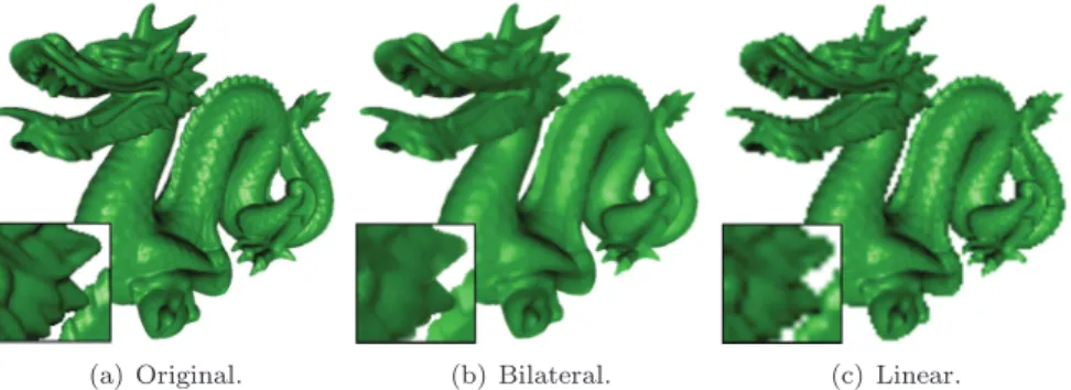
(a) Original. (b) Bilateral. (c) Linear.
Figure 1. The dragon dataset rendered (a) normally at full opacity at 5122, (b) upsampled from a 1282 rendering using our joint bilateral filter that combines a low-resolution color buffer with a high-resolution depth buffer, and (c) upsampled linearly from a 1282 rendering. When applied to volumes, our bilateral upsam-pling technique is an acceleration method that removes unwanted aliasing while still preserving sharp features.
on intensities. The introduction of a separate reference image for performing the feature preservation is useful in some cases and is termed joint (or cross) bilateral filtering [Petschnigg et al. 04, Eisemann and Durand 04]. This has recently been shown to be useful for enhancing images with solutions that have been computed over downsampled images [Kopf et al. 07]. We build on this latter approach to improve volume rendering performance by rendering normally into a downsampled image and combining that with a low-cost ref-erence image computed at full size. Instead of pixel intensities, our refref-erence image contains depth information that can be used to encode the shape of the volume in a full-size image. The result is an image that preserves the color of the downsampled image with the sharp features of the reference image. For opaque renderings, this has the appearance of smoothing the geometry in object space, though it happens entirely in image space. Figure 1 shows an example of the effect of our algorithm applied to an opaque rendering of a triangle mesh.
3. The Technique
Our acceleration technique is briefly summarized by the following steps: 1. Render the volume into a small offscreen image I using an existing
volume rendering algorithm.
2. Render the boundary geometry of the volume at full size and capture the depths of the fragments in a reference imageR.
3. Upsample the offscreen imageIto full size using texturing hardware and combine it with the reference imageR using the joint bilateral filter. Figure 2 shows the visual effect of our algorithm on a volume. The details of each step in our method are described in the remainder of this section.
3.1. The Joint Bilateral Upsampling Filter
The original bilateral filter uses both a domain (spatial) and a range filter kernel on the input image to produce a denoised output image. For some positionp, the filtered result is
Jp= 1
kp
q∈Ω
Iqf(p−q)g(Ip−Iq ),
where f is the spatial filter, such as a low-pass filter that operates on pixel colors centered over p, g is the range filter kernel, such as a low-pass filter
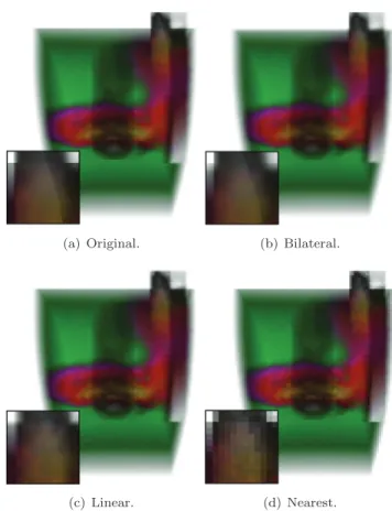
(a) Original. (b) Bilateral.
(c) Linear. (d) Nearest.
Figure 2. The SPX dataset rendered using a software ray caster (a) normally at a 10242 resolution at one frame per second, and upsampled from a 1282 image at ten frames per second using (b) our feature-preserving joint bilateral upsampling, (c) linear interpolation, and (d) nearest neighbor interpolation (similar to a method that casts one ray per 82 pixel grid). Only the original and our bilateral method preserve the diagonal edge that appears in the center of the inset images.
that operates on pixel intensities centered overp, Ω is the spatial support of the kernelsf and g, and kp is the normalization computed as the sum off andg filter weights. Intuitively, f ·g is just a new filter kernel that changes per pixel to respect intensity boundaries:
The joint bilateral upsampling filter uses separate images at different reso-lutions for the domain and range to compute an upsampled solutionS from
a given high-resolution imageI and a low-resolution solutionR that is used as a reference image: Sp= 1 kp q↓∈Ω Rq↓f(p↓−q↓)g(Ip−Iq ),
wherepandqdenote coordinates inI, andp↓andq↓denote the corresponding coordinates in the low-resolution reference imageR. This formulation is used to compute costly solutions for high-resolution images at less costly lower resolutions. Our algorithm is different, as an inexpensive solutionR at high resolution is used to upsample a low-resolution imageI. In the same notation, our filter could be expressed as
Sp= 1
kp
q∈Ω
Iq↓f(p↓−q↓)g(Rp−Rq ),
wherepandqdenote integer coordinates in the high-resolution reference image
R, andp↓ andq↓ denote the corresponding fractional coordinates in the low-resolution image I. Note that in this formulation, the domain of the filter becomes dependent on the final image size desired, not the size of the reference image, as was the case previously.
3.2. Computing the Reference Image
To preserve features in our upsampled version, a full-resolution reference im-age is needed for the range component of the bilateral filter. This reference image needs to be fast to compute and general enough to apply to a vari-ety of volume renderers. For unstructured grids, it is common to represent the domain (or boundaries) of the volume to facilitate the understanding of the features that are contained therein. Fortunately, the boundaries are easy to capture—they are often already used by volume rendering algorithms as starting points for ray traversal [Bunyk et al. 97, Weiler et al. 03] or as the base case for object-space LOD [Callahan et al. 05a]. Other sharp boundaries within the volume could be used as well, such as those provided by isosurfaces, if they are readily available.
For our bilateral upsampling to faithfully preserve the features of the vol-ume’s domain, more than just the frontmost boundary needs to be captured. Multiple depth layers are already used by many volume renderers to handle nonconvex meshes either in software [Bunyk et al. 97] by creating a sorted depth list for each pixel, or in hardware [Bernardon et al. 06, Weiler et al. 04] using depth peeling [Everitt 99]. Depth peeling is a multipass algorithm that
captures one layer of depth on each pass, starting with the nearest fragment per pixel, then the second nearest, third nearest, and so on. This can be per-formed efficiently in hardware by rendering the first pass normally, resulting in a depth buffer of the nearest surface. In subsequent passes, the depth buffer computed in the previous pass is used topeel away depths less than or equal to those already captured in previous passes. These depth peeling passes can even be reduced to a single pass using stencil routing [Bavoil and Myers 08]. To compute the reference image in an existing volume rendering algorithm, we leverage the framework already in place for capturing depths whenever possible. If depths are not already captured, we simply add a depth peeling pass to the renderer that uses shaders and fragment tests to collect the depth layers in a fixed number of offscreen textures. The number of depth passes that are used is dependent on the volume being rendered and the opacity at which it is being rendered. In our experience, two or three layers are sufficient for most unstructured volumes to capture the visible boundary features.
3.3. Implementation
Our joint bilateral upsampling is implemented with minimal changes to an existing algorithm. The low-resolution image I and the reference image R are rendered offscreen. Then in a final pass, a full-resolution, screen-aligned quadrilateral is drawn that binds both images as textures and uses a frag-ment shader to perform the joint bilateral filter. Texturing hardware will upsample the small resolution to full resolution to be used in the shader. This upsampling can be as simple as a nearest neighbor interpolant, as we noticed little difference in the final image between that and a linear interpolant. In the shader, theI andR textures are accessed using the same coordinates to retrieve color and depth information used in the joint bilateral filter.
For each pixel p in the final image, the joint bilateral filter is a low-pass filter that blurs a fixed neighborhood around p to remove noise. Choosing the spatial support Ω for the filter should be based on the amount of upsam-pling that is being performed on I, i.e., more blurring is required for higher upsampling factors. We match the spatial support for the joint bilateral filter with the spatial support for the linear interpolation performed by texturing hardware: if upsampling to 10242, a 5122image will use Ω = 4, a 2562image will use a Ω = 8, etc.
For domain and range filters,f andg, we use Gaussian low-pass filters:
f(x, y) =g(x, y) =e−D(x,y)2/2σ2.
For the domain filter f operating on the low-resolution image I, D(x, y) is the distance between (x, y) and the origin of the filterp, andσis the spread
of the Gaussian, or Ω/2. For the range filter g operating on the reference image R, D(x, y) is the difference between the depth value at (x, y) and the depth value at p. For multiple depth layers, this simply becomes the dis-tance between the vectors defined at (x, y) andp. The rangeσ is the value that expresses the resolution of the depth features that should be preserved. Thus, the range σ is dependent on the resolution of the depth buffer and should be as low as possible to capture depth changes, without causing arti-facts due to depth precision. We have found a σ= 0.01 for the range to be adequate.
4. Performance
To demonstrate the flexibility of our joint bilateral upsampling algorithm for unstructured grids, we show how adding it to existing source code for three popular algorithms can improve the interactivity and quality of renderings.
4.1. Improving Interactivity
The fragment shader for bilateral sampling itself is relatively inexpensive; for a 10242image, kernel sizes of 4, 8, and 16 achieve framerates of 100 fps, 50 fps, and 15 fps, respectively, on an NVIDIA Quadro FX 5600 graphics card. To demonstrate the improvements due to our technique, we used the SPX (13K tetrahedra), Blunt Fin (187K tetrahedra), F117 (240K tetrahedra), and SPX2 (828K tetrahedra) datasets to gather statistics for upsampling to 10242 from 5122with a kernel size of 4, 2562with a kernel size of 8, and 1282with a kernel size of 16. The upsampled times were compared with the original rendering times for a 10242image. At each resolution, we rendered the dataset from 14 viewpoints, defined by the corners and faces of a cube around the dataset, and averaged the times. All of these statistics were rendered on a machine with 2 Dual Opteron 2.25 GHz processors, 4 GB RAM, and an NVIDIA Quadro FX 5600 graphics card with 1.5 GB RAM.
The first algorithm that we modified is a software ray caster from Bunyk et al. [Bunyk et al. 97] that has freely available source code and runs completely on the CPU. The algorithm first rasterizes boundary triangles to capture starting and ending points for the rays at each pixel. It then marches rays through the volume cell to cell by exploiting connectivity of cell faces. To make the modification, we perform the ray casting as normal, except into a small image. We then use the existing depth capturing code to find the boundary depths in a large image. These two images are then bound as textures and rendered to the screen using our fragment shader written in OpenGL. Table 1 shows results for several datasets, comparing times for the varying resolutions.
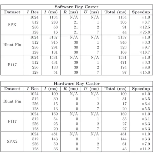
Software Ray Caster
Dataset I Res I (ms) R(ms) U (ms) Total (ms) Speedup
SPX 1024 1134 N/A N/A 1134 ×1.0 512 283 21 1 305 ×3.7 256 68 21 2 91 ×12.5 128 16 21 7 44 ×25.8 Blunt Fin 1024 3137 N/A N/A 3137 ×1.0 512 915 30 1 946 ×3.3 256 291 30 2 323 ×9.7 128 131 30 7 168 ×18.7 F117 1024 1531 N/A N/A 1531 ×1.0 512 431 39 1 471 ×3.3 256 133 39 2 174 ×8.8 128 51 39 7 97 ×15.8
Hardware Ray Caster
Dataset I Res I (ms) R(ms) U (ms) Total (ms) Speedup
Blunt Fin 1024 109 N/A N/A 109 ×1.0 512 30 0 1 31 ×3.5 256 15 0 2 17 ×6.4 128 13 0 7 20 ×5.5 F117 1024 169 N/A N/A 169 ×1.0 512 54 0 1 55 ×3.1 256 25 0 2 27 ×6.3 128 20 0 7 27 ×6.3 SPX2 1024 481 N/A N/A 481 ×1.0 512 143 0 1 144 ×3.3 256 59 0 2 61 ×7.9 128 36 0 7 43 ×11.2 Table 1. Timing statistics in milliseconds for a software and a hardware ray caster for various resolutions upsampling to 10242 using our technique. Timings are sepa-rated into the low-resolution image (I) pass, the high-resolution solution (R) pass, and the upsampling pass (U). The 1024 resolution represents the time for a full-quality image without upsampling. A zero measurement indicates that the pass takes much less than one millisecond and has no measurable impact on the final timing.
In our experiments, the acceleration for these datasets ranges from about 16 times to 26 times for 1282 resolution images upsampled to 10242.
The second algorithm that we modified is a hardware-assisted ray-casting algorithm from Bernardon et al. [Bernardon et al. 06] that is freely available and is written in DirectX 9. As with the software ray caster, we were able to adapt the algorithm to render into a small offscreen buffer and use the existing depth peeling routines to capture the depth in a full-size offscreen buffer. An
HLSL program was then used to perform the joint bilateral upsampling and display the final image. Table 1 shows a comparison of times for varying resolutions. With the hardware ray caster, acceleration gains range from about 6 times for the smallest dataset to about 11 times for the largest for 1282or 2562 resolution images upsampled to 10242.
4.2. Improving Quality
By using a full-size reference image, our joint bilateral upsampling is able to achieve better imagery than upsampling alone. We show this both quanti-tatively and visually. Figure 3 shows rate distortion curves for the quality of upsampling using our joint bilateral filter versus a simple linear interpola-tion (as provided by texturing hardware). The measurements were computed using root mean squared error (RMSE) comparisons between full-quality im-ages at 10242and images upsampled at various resolutions. In all cases, our upsampling exhibits less error than with linear interpolation alone. Figure 4 shows rendered solutions at various resolutions for a visual comparison of the quality change.
One interesting application of our filter is in improving the appearance of existing acceleration techniques by denoising results while still preserving edges. We added our upsampling filter to the hardware-assisted visibility sort-ing (HAVS) volume rendersort-ing algorithm [Callahan et al. 05b] to improve the
Figure 3. Rate distortion curves for the software ray caster comparing RMS error of full-quality images versus our method and linear upsampling at different factors.
Figure 4. The Blunt Fin dataset rendered into a 10242 image at (a) full quality and upsampled from (b) 5122, (c) 2562, and (d) 1282 using our technique.
visual results of a dynamic level-of-detail algorithm that operates by sampling the geometry of the volume [Callahan et al. 05a]. HAVS sorts the triangles that compose the mesh first in object space using a simple sorting routine, then in image space by storing a fixed number of fragments that are stored and composited in textures. The sample-based level of detail limits the num-ber triangles before the sorting, based on pre-computed importances, to make the rendering much faster. In an attempt to maintain coverage of the volume in the final image, the boundary triangles of the volume are kept separately from the internal triangles and are not sampled. Because the level-of-detail algorithm already uses boundary geometry as the base sampling case, we were able to add a simple depth peeling pass to render the boundary geometry into a reference image to be used as a reference in the joint bilateral upsampling. Due to the nature of the algorithm, HAVS is more vertex-bound than pixel-bound. Thus, the acceleration when using our upsampling approach is negligi-ble on the most recent graphics cards. However, our technique can be used to improve image quality of the sample-based level of detail. The sample-based simplification described above has the side effect of producing high-frequency error in the reduced representation, unlike domain-based simplification tech-niques (i.e., simplification via edge collapses [Garland and Zhou 05]). Using
Figure 5. Our joint bilateral filter can be used to smooth noisy artifacts even when acceleration gains are minimal. This figure shows the San Fernando Earthquake dataset (1.4 million tetrahedra) rendered using HAVS [Callahan et al. 05b] with sample-based simplification [Callahan et al. 05a]. (a) The full-quality image is ren-dered at 1.7 fps compared with (b) sampling 10% of the geometry (20 fps) and (c) sampling 10% of the geometry then using our joint bilateral filter without upsam-pling to remove the high-frequency error while still preserving boundary features (15 fps).
our joint bilateral filter on the resulting imagery, we are able to reduce the noise and improve the overall appearance of the technique with little effect on the performance. Figure 5 shows an example of this LOD before and after our joint bilateral filter is applied. Because the acceleration due to the LOD algorithm is dominant, the rendered imageI does not need to be computed at a reduced representation, and upsampling is not necessary.
5. Discussion
Because our method is simple, it can easily be utilized as a technique to accelerate interaction, while still allowing full-quality images to be rendered
when the user stops interacting with the viewing parameters. Tools such as ParaView1 use a similar strategy during rendering, by changing either the number of slices for texture-based methods or the number of rays for ray casters. We envision our algorithm as a replacement or enhancement for these existing techniques because it produces better approximations of the full-quality image with fewer visual artifacts. Because it is easy to change the speed/quality trade-off by adjusting the upsampling factor, our algorithm could also be used for dynamic level of detail.
Many existing acceleration techniques that trade off speed for image qual-ity create high-frequency error in the resulting image in the form of stair-casing or aliasing artifacts. In contrast, our method produces low-frequency error, which results in more visually pleasing images that retain edges that are supposed to be in the image, while removing those that are not. Although we use joint bilateral upsampling, other upsampling strategies have been in-troduced [Wolberg 90] and could be used instead. However, without the additional shape information that is provided by the reference image, other upsampling strategies are not likely to perform as well, as they can result in halos and other undesired artifacts, as shown by Kopf et al. [Kopf et al. 07].
Our solution for performing joint bilateral upsampling for volume rendering was implemented in OpenGL and DirectX using fragment programs. We also implemented the bilateral filter with NVIDIA’s CUDA library, which is efficient for offscreen processing but was several times slower for interactive rendering due to the costs of transferring textures to the graphics engine for display after processing. Even for large images and large filter domains, the computational cost of our algorithm is not high relative to the volume rendering cost. As with most acceleration techniques, the trade-off for image quality is performance (i.e., more downsamping results in higher speed).
Our experiments included several datasets at various sizes to demonstrate the acceleration that our technique can provide. The size of datasets used in these experiments was limited by the volume rendering methods we used, not by any limitations of our acceleration technique. Volume rendering algorithms that handle larger datasets, such as ray casters that use bricking strategies for memory management [Muigg et al. 07] or point-based techniques that are fragment-bound [Anderson et al. 07], would also benefit from our acceleration technique.
There are several limitations of our upsampling algorithm. The approach is useful only if the desired images are relatively large, which may not al-ways the case. In addition, the upsampling only works as an acceleration technique for algorithms that are inherently pixel-bound, such as ray cast-ers. The current implementation can handle upsampled images up to 10242 without too much problem, but scaling it to large or multiple displays would
require a more efficient bilateral filter, such as an approximation [Paris and Duran 06], to keep framerates interactive. Finally, our technique works very well for unstructured volume rendering because the boundary of these vol-umes is typically of interest in the final visualization. For structured volvol-umes, this is not often the case. Thus, a reference image computed from internal features, such as an isosurface, would be necessary for a quality upsampling. Extending our method to structured volumes would require the difficult task of finding the right surface (or set of surfaces) that would preserve the features in the upsampled volume rendering. Addressing these limitations would be an interesting avenue of future work.
Acknowledgments. The authors thank Jens Kr¨uger and Peter Shirley for useful discussion, the reviewers for their insightful suggestions, the Stanford University Computer Graphics Laboratory for the Dragon dataset, O’Hallaron and Shewchuk (CMU) for the earthquake dataset, Notrosso ( ´Electricit´e de France) for the SPX dataset, Haimes (MIT) for the F117 dataset, and Hung and Buning (NASA) for the Blunt Fin dataset. This research has been funded by the Department of Energy SciDAC (VACET and SDM centers), the National Science Foundation (grants CNS-0751152, CCF-0528201, OCE-0424602, CNS-0514485, IIS-0513692, CCF-0401498, OISE-0405402, CNS-0551724), IBM Faculty Awards (2005, 2006, and 2007), and a University of Utah Graduate Research Fellowship.
References
[Anderson et al. 07] E. W. Anderson, S. P. Callahan, C. E. Scheidegger, J. Schreiner, and C. T. Silva. “Hardware-Assisted Point-Based Volume Ren-dering of Tetrahedral Meshes.” InBrazilian Symposium on Computer Graphics and Image Processing (SIBGRAPI), pp. 163–170. Los Alamitos, CA: IEEE Press, 2007.
[Bavoil and Myers 08] L. Bavoil and K. Myers. “Deferred Rendering using a Stencil Routed K-Buffer.” In ShaderX6: Advanced Rendering Techniques, edited by W. Engel, Chapter 3.5, pp. 189–198. Boston, MA: Course Technology, 2008. [Bernardon et al. 06] F. F. Bernardon, C. A. Pagot, J. L. D. Comba, and C. T. Silva.
“GPU-Based Tiled Ray Casting using Depth Peeling.”journal of graphics tools 11:4 (2006), 1–16.
[Bunyk et al. 97] P. Bunyk, A. Kaufman, and C. T. Silva. “Simple, Fast, and Robust Ray Casting of Irregular Grids.” InProc. of Dagstuhl, Scientific Visualization, pp. 30–36. Los Alamitos, CA: IEEE Press, 1997.
[Callahan et al. 05a] S. P. Callahan, J. L. D. Comba, P. Shirley, and C. T. Silva. “Interactive Rendering of Large Unstructured Grids Using Dynamic Level-of-Detail.” InProceedings of IEEE Visualization, pp. 199–206. Los Alamitos, CA: IEEE Press, 2005.
[Callahan et al. 05b] S. P. Callahan, M. Ikits, J. L. D. Comba, and C. T. Silva. “Hardware-Assisted Visibility Sorting for Unstructured Volume Rendering.” IEEE Transactions on Visualization and Computer Graphics11:3 (2005), 285– 295.
[Cignoni et al. 04] P. Cignoni, L. De Floriani, P. Magillo, E. Puppo, and R. Scopigno. “Selective Refinement Queries for Volume Visualization of Un-structured Tetrahedral Meshes.” IEEE Transactions on Visualization and Computer Graphics 10:1 (2004), 29–45.
[Danskin and Hanrahan 92] J. Danskin and P. Hanrahan. “Fast Algorithms for Volume Ray Tracing.” InWorkshop on Volume Visualization, pp. 91–98. New York: ACM Press, 1992.
[Eisemann and Durand 04] E. Eisemann and F. Durand. “Flash Photography En-hancement via Intrinsic Relighting.” Proc. SIGGRAPH ’04, Transactions on Graphics 23:3 (2004), 673–678.
[Engel et al. 06] K. Engel, M. Hadwiger, J. M. Kniss, C. Rezk-Salama, and D. Weiskopf. Real-Time Volume Graphics. Wellesley, MA: A K Peters, 2006. [Everitt 99] C. Everitt. “Interactive Order-Independent Transparency.” White
pa-per, NVIDIA Corporation, 1999.
[Garland and Zhou 05] M. Garland and Y. Zhou. “Quadric-Based Simplification in Any Dimension.” ACM Transactions on Graphics 24:2 (2005), 209–239. [Kopf et al. 07] J. Kopf, M. Cohen, D. Lischinski, and M. Uyttendaele. “Joint
Bilateral Upsampling.” Proc. SIGGRAPH ’07, Transactions on Graphics26:3 (2007), Article No. 96.
[Kr¨uger and Westermann 03] J. Kr¨uger and R. Westermann. “Acceleration Tech-niques for GPU-based Volume Rendering.” InProceedings of IEEE Visualiza-tion, p. 38. Los Alamitos, CA: IEEE Press, 2003.
[Levoy 90a] M. Levoy. “Efficient Ray Tracing of Volume Data.”ACM Transactions on Graphics9:3 (1990), 245–261.
[Levoy 90b] M. Levoy. “A Hybrid Ray Tracer for Rendering Polygon and Vvolume Data.” IEEE Computer Graphics and Applications2:4 (1990), 33–40.
[Levoy 90c] M. Levoy. “Volume Rendering by Adaptive Refinement.” The Visual Computer 6:1 (1990), 2–7.
[Muigg et al. 07] P. Muigg, M. Hadwiger, H. Doleisch, and H. Hauser. “Scalable Hybrid Unstructured and Structured Grid Raycasting.”IEEE Transactions on Visualization and Computer Graphics 13:6 (2007), 1592–1599.
[Paris and Duran 06] S. Paris and F. Duran. “A Fast Approximation of the Bilateral Filter using a Signal Processing Approach.” In Computer Vision – ECCV 2006: 9th European Conference on Computer Vision, Graz, Austria, May 7– 13, 2006, Proceedings, Part IV, edited by A. Leonardis, H. Bischof, and A. Pinz, pp. 568–580, Lecture Notes in Computer Science 3954. Berlin-Heidelberg: Springer Verlag, 2006
[Petschnigg et al. 04] G. Petschnigg, R. Szeliski, M. Agrawala, M. Cohen, H. Hoppe, and K. Toyama. “Digital Photography with Flash and No-Flash Image Pairs.” Proc. SIGGRAPH ’04, Transactions on Graphics 23:3 (2004), 664–672. [Roettger et al. 03] S. Roettger, S. Guthe, D. Weiskopf, and T. Ertl. “Smart
Hardware-Accelerated Volume Rendering.” InProc. Data Visualization Sympo-sium, pp. 231–238. Aire-la-Ville, Switzerland: Eurographics Association, 2003. [Silva et al. 05] C. T. Silva, J. L. D. Comba, S. P. Callahan, and F. F. Bernardon. “GPU-Based Volume Rendering of Unstructured Grids.” Brazilian Journal of Theoretic and Applied Computing (RITA)12:2 (2005), 9–29.
[Tomasi and Manduchi 98] C. Tomasi and R. Manduchi. “Bilateral Filtering for Gray and Color Images.” In ICCV, pp. 839–846. Los Alamitos, CA: IEEE Press, 1998.
[Weiler et al. 03] M. Weiler, M. Kraus, M. Merz, and T. Ertl. “Hardware-Based Ray Casting for Tetrahedral Meshes.” In Proceedings of IEEE Visualization, pp. 333–340. Los Alamitos, CA: IEEE Press, 2003.
[Weiler et al. 04] M. Weiler, P. N. Mall´on, M. Kraus, and T. Ertl. “Texture-Encoded Tetrahedral Strips.” In Symposium on Volume Visualization, pp. 71–78. Los Alamitos, CA: IEEE Press, 2004.
[Wolberg 90] G. Wolberg. Digital Image Warping. Los Alamitos, CA: IEEE Com-puter Society Press, 1990.
Web Information:
http://jgt.akpeters.com/papers/CallahanSilva09/
Steven P. Callahan, Scientific Computing and Imaging Institute, University of Utah, 72 S. Central Campus Drive, WEB 3750, Salt Lake City, UT 84112
Cl´audio T. Silva, Scientific Computing and Imaging Institute, University of Utah, 72 S. Central Campus Drive, WEB 3750, Salt Lake City, UT 84112