Automatic Cast Shadow Detection
Chanchal Chitwan
Department of Computer Science and Engineering National Institute of Technology Rourkela
Automatic Cast Shadow Detection
Thesis submitted in partial fulfillment of the requirements for the degree of
Bachelor of Technology
inComputer Science and Engineering
byChanchal Chitwan
(Roll No. 108CS037)under the guidance of
Prof. Banshidhar Majhi
Department of Computer Science and Engineering National Institute of Technology Rourkela
Computer Science and Engineering
National Institute of Technology Rourkela
Rourkela-769 008, India. www.nitrkl.ac.inProf. Banshidhar Majhi
Professor
May 14, 2012
Certificate
This is to certify that the work in the project entitled Automatic Cast Shadow Detection
by Chanchal Chitwan is a record of an original work carried out by him under my supervision and guidance in partial fulfillment of the requirements for the award of the degree of Bachelor of Technology in Computer Science and Engineering. Neither this project nor any part of it has been submitted for any degree or academic award elsewhere.
4
Acknowledgement
I express my profound gratitude and indebtedness to Prof. B. Majhi, Department of Computer Science and Engineering, NIT Rourkela for intruding the present topic and for his inspiring intellectual guidance, constructive criticism and valuable suggestion throughout the project work. I am also thankful to Mr. Kalyan Hathi(M.Tech research scholar), Department of Computer Science and Engineering for guiding and motivating throughout the project.
Finally I would like to thank to my parents and colleagues for their support and motivation to complete this project.
Date: 14 may, 2012
Rourkela
5
Abstract
For human eyes it is not difficult to distinguish shadows from objects. However in most situations, identifying shadows by computer is a challenging research problem which is a type of segmentation problem in digital image processing. In real time systems, the automated path finding robots can easily detect obstacle and take alternate path but the problem is that they also consider shadow as a part of obstruction. In this project a hybrid algorithm is proposed to detect and extract cast shadow from a still image using fuzzy divergence thresholding and C1C2C3 color
invariant feature. The proposed algorithm consists of two modules. The first module gives the edge map of shadow whereas the second module gives the object edge map. Exploiting the geometric property of shadow and these two edge maps, cast shadow region is extracted. Finally it is remapped on original image to visualize the extracted region. Some of the important applications can be in processing satellite images, object tracking in video and, image matching and enhancement.
6
Contents
1 Introduction 8 1.1 Problem statement 8 1.2 Applications 8 1.3 What is a Shadow? 8 1.3.1 Geometric property 9 1.3.2 Spectral property 10 2 Literature Survey 112.1 Model based techniques 11
2.2 Property based techniques 12
2.3 Fuzzy divergence segmentation 12
2.4 C1C2C3invariant color model 16
2.5 Sobel operator 17 2.6 Morphological operation 18 3 Proposed algorithm 19 4 Experimental results 28 5 Constraints 29 6 Conclusion 29 7 Future work 30 8 References 31
7 Figure
No.
Description Page No.
1. Geometrical property of shadow 9
2. Cameraman 14
3. Histogram for Cameraman 14
4. Divergence vs. gray level graph for Cameraman 14
5. Threshold image of Cameraman 14
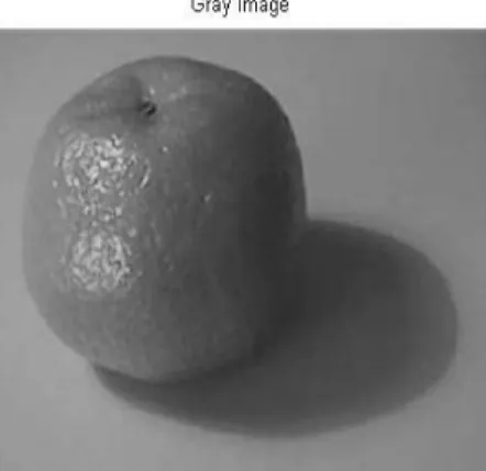
6. Gray image of Orange 15
7. Histogram of Orange 15
8. Divergence vs. gray level graph for Orange 15
9. Threshold image of Orange 15
10. Orange 16
11. Resultant image using C1C2C3 color model 16
12. Gx 17
13. Gy 17
14. Circle 17
15. Edge of the Circle using Sobel 17
16. Modular view of the algorithm 19
17. Sample image 23
18. Gray image of Orange 23
19. Divergence vs. gray level graph for Fig. 18. 23
20. Threshold image of Orange 23
21. Threshold image after morphological operation 24
22. Sobel edge map 24
23. Result after using Invariant color model 24 24. Divergence vs. Gray level graph for Fig. 23. 24
25. Threshold image of Fig. 23. 25
26. After morphological operation on Fig. 25. 25
27. Object edge map 25
28. Shadow line 25
29. Open cast shadow region 26
30. Closed cast shadow region 26
31. Block diagram for cast shadow detection 27
32. Experimental results 28
8
1.
Introduction
1.1. Objective
The aim of this project is to detect and extract cast shadow region from a still image. As the aim is to identify a particular region in a digital image so, it is a problem of segmentation under digital image processing.
1.2. Applications
There are many situations when we try to avoid shadow as it becomes undesired and unwanted part which deteriorates our result. Those situations may be either object detection or automated path finding robot or scene understanding or traffic surveillance or face recognition or image segmentation. Some of the important applications are processing satellite images, object tracking in video and, image matching and enhancement. Another application is to design an automated robot which can find path itself and in case of encountering an obstacle it will take alternate path while in case of shadow detection it will cross over it by neglecting.
1.3. What is a Shadow?
A shadow occurs when an object partially or totally occludes direct light from a source of illumination. It can be classified into two groups: self shadow and cast shadow. Self shadow is the region of shadow which is projected on the object where as cast shadow is the region of shadow which is projected on the surface or background (Fig. 1.). Again cast shadow can be classified into two parts: umbra and penumbra. The part of cast shadow where direct light can not reach completely due to obstruction by object is called
9
umbra. The part of cast shadow where direct light is not completely blocked by object is called penumbra.
1.3.1. Geometric properties of shadow
10
Geometric property of shadow is very useful for shadow extraction. There is single light source (Fig. 1.). Light is obstructed by the object and shadow is formed. ABCD is self shadow region. EDC is cast shadow region. The intensity of self shadow pixels is lower than intensity of cast shadow pixels. The intensity of directly illuminated part of object is grater than both of cast shadow and self shadow pixels.
1.3.2 Spectral properties of shadow
The radiance of light LrȜ3UHIOHFWHGDWDJLYHQSRLQW3RQDVXUIDFHLQWKH'VSDFHLV
formulated as
LrȜ3 /aȜ/bȜ3/cȜ3 (1)
Where La(Ȝ/bȜ3/cȜ3DUHWKHDPELHQWUHIOHFWLRQWHUPWKHERG\UHIOHFWLRQWHUPDQGWKH
VXUIDFHUHIOHFWLRQWHUPUHVSHFWLYHO\DQGȜLVWKHZDYHOHQJWKThe ambient illumination term does not vary with geometry because it is accounted for all the light indirectly reflected among surfaces in the environment. In case of no direct light due to obstruction by an object, the radiance of reflected light
LrVKDGRZȜ3 /aȜ (2)
11
2. Literature Survey
Basically shadow detection techniques can be classified into two groups: model based and property based techniques which are discussed later. Apart from that Fuzzy divergence, C1C2C3
invariant color model, Sobel operator and, Morphological operation have been discussed in this section subsequently.
2.1. Model based techniques
The main drawback of model based technique is that it requires priori knowledge of the geometry of the scene, the object and the illumination. In this way this technique is applicable to only limited types of problems. Under this category various works have been done.A. Huertas et al. [3] described the problem of detecting buildings in aerial images. Y. Liow et al.[4] developed the Use of shadows for extracting buildings in aerial images. A. Yoneyama et al. [5] worked on moving cast shadow elimination for robust vehicle extraction based on 2d joint vehicle/shadow models. Technically all of them worked on the principle of matching sets of geometric features such as edges, lines or corners to 3D object models.
2.2. Property based techniques
In property based technique shadow is identified exploiting features such as geometry, brightness or color of the shadow. This technique has overcome the limitations in model based techniques by using spectral and geometrical features of shadow. Under this category various works have been done using different features of shadow. Using luminance information J.M. Scanlan et al. [6] gave a shadow detection and removal algorithm for 2-d images. Shadow segmentation and classification has been done exploiting geometry and intensity information by C. Jiang et al. [9]. Edge and texture informations are used by J. Stauder et al. [7]for detection of moving cast
12
shadows for object segmentation. T. Horprasert et al. [9] gave statistical approach for real-time robust background subtraction and shadow detection. HSI model is used by R. Cucchiara et al. [11] for detecting objects, shadows and ghosts in video streams by exploiting color and motion information. Luminance, chrominance and gradient intensity information is exploited by G.S.K. Fung et al. [8] to detect moving cast shadows for monocular color image sequences.YUV model is exploited byO. Schreer et al. [10]who proposed fast and robust shadow detection in videoconference applications. Elena Salvador et al. [1] proposed cast shadow using Thresholding and C1C2C3 invariant color model.
Shadow identification and classification using invariant color model [1] is the paper that I have studied and carried forward my project work. In this paper they have used Sobel operator on luminance information to get shadow edge map and C1C2C3 invariant color model is used for
object edge map.
2.3. Fuzzy divergence segmentation
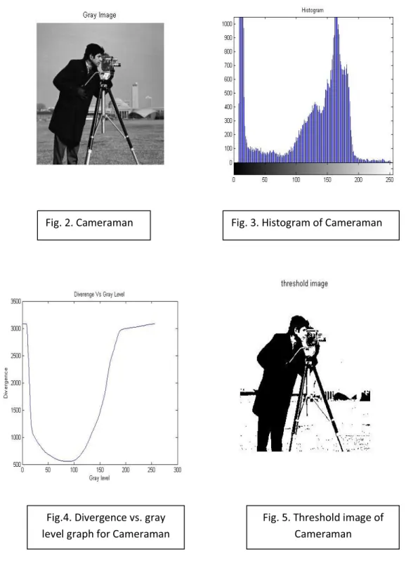
This is the recent segmentation technique to minimize the fuzzy divergence value or the separation between the actual and the ideal thresholded image. The membership value of pixel is calculated using gamma function. This is based upon the fuzzy set theory which gives better result in several cases those may be caused due to imprecision of gray levels of an image or ambiguity in some definition such as boundaries between the regions. Similarly shadow pixels nearer to boundary have also ambiguity. It is difficult to know whether they belong to shadow part, object or background. 7KDW¶V ZK\ WKLV WHFKQLTXH LV XVHG WR HQKDQFH WKH SUHFLVLRQ LQthe result.
13
For a given gray image, at first following two attributes are calculated for each gray level(t)
ZKHUHW «up to 255
µ
0=
σసబǤୡ୭୳୬୲ሺሻ σ౪సబୡ୭୳୬୲ሺሻ (3)µ
1=
σಽషభసశభǤୡ୭୳୬୲ሺሻ σైషభస౪శభୡ୭୳୬୲ሺሻ (4)Where, count(f) is the no. of occurrences of gray level f in the image, fij is (i, j)th pixel of the
image, t is the threshold value.
Membership value is calculated for each pixel and stored in a matrix for each threshold value. Membership value (
µ(f
ij)
) is defined as following:µ(f
ij) = exp(-c. | f
ij- µ
0| )
if fijWIRUEDFNJURXQG (5)exp (-c. | f
ij- µ
1| )
if f
ij> t, for objectWhere,
µ( f
ij)
and,
c = 1/256For a particular threshold, only one condition will be true always which tells how much a pixel belongs to background and how much to object.
In this way we have 256 fuzzyfied images for each threshold value. Now divergence value is calculated with respect to ideally thresholded image. So value of q is taken as 1 for ideally thresholded image in eq. (6) which leads to new eq. (7).
p =
µ
A(f
ij)
q = µ
B(f
ij)
D(A, B) =
σ
σ
ேିଵሾʹ െ ሺͳ െ ݍሻǤ ݁
ିെ ሺͳ െ ݍሻǤ ݁
ିሿ
௧ୀ ெିଵ ௧ୀ (6)D(A, B) =
σ
σ
ேିଵሺʹ െ ሺͳ െ ሻǤ ݁
ିଵെ Ǥ ݁
ଵିሻ
௧ୀ ெିଵ ௧ୀ (7)Using eq. (7) divergence value is calculated for each fuzzy image. Minimum divergence value is searched and its corresponding gray level is taken as optimum threshold value.
14 Implementation results
Fig. 2. Cameraman Fig. 3. Histogram of Cameraman
Fig.4. Divergence vs. gray level graph for Cameraman
Fig. 5. Threshold image of Cameraman
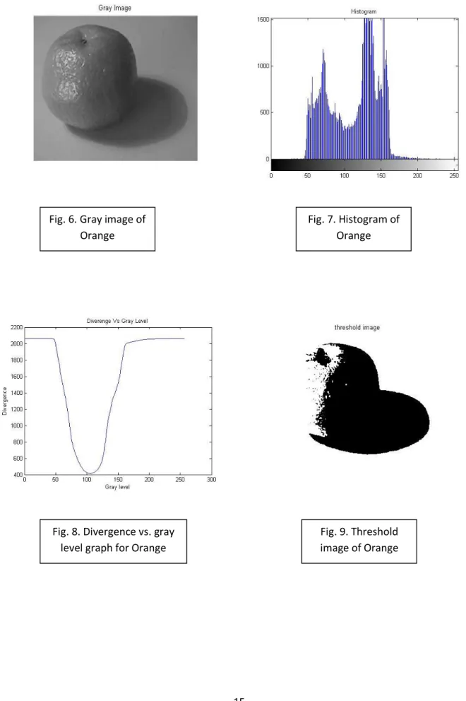
15 Fig. 6. Gray image of
Orange
Fig. 7. Histogram of Orange
Fig. 8. Divergence vs. gray level graph for Orange
Fig. 9. Threshold image of Orange
16
2.4. C1C2C3 invariant color model
Invariant color model is defined as following:
C1(x, y)
=
ି ࡾሺ࢞ǡ࢟ሻ ࢇ࢞ሺࡳሺ࢞ǡ࢟ሻǡሺ࢞ǡ࢟ሻሻ (8) C2(x, y)=
ି ࡳሺ࢞ǡ࢟ሻ ࢇ࢞ሺࡳሺ࢞ǡ࢟ሻǡࡾሺ࢞ǡ࢟ሻሻ (9) C3(x, y)=
ି ሺ࢞ǡ࢟ሻ ࢇ࢞ሺࡳሺ࢞ǡ࢟ሻǡࡾሺ࢞ǡ࢟ሻሻ (10)Where R(x, y), G(x, y), B(x, y) are red, green and blue color components respectively in RGB image. This color model adopted because it suppresses the background and shadow pixels in the image. It is unstable near the black vertex of RGB space. Implementation result (Fig. 11.) is shown applied on Orange (Fig. 10.).
17
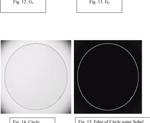
2.5. Sobel operator
There are various edge detection techniques i.e. Canny, Laplace, Prewitt, Sobel edge detection. Basically edge detection techniques identify points in a digital image where brightness changes sharply or has discontinuity. Sobel operator can even work for the detection of thin edge line.
7KDW¶VZK\Sobel operator has been has been used.To detect edge in an image, it is filtered in both X and Y directions using Gx (Fig. 12.) and Gy (Fig.13.) Sobel operators respectively and the
results are added together.
-1 0 1 -2 0 2 -1 0 1 -1 -2 -1 0 0 0 1 2 1
Fig. 14. Circle Fig. 15. Edge of Circle using Sobel Fig. 12. Gx Fig. 13. Gy
18
2.6. Morphological operations
There are four basic operations for morphological operation on a digital image. Those are erosion, dilation, opening and closing. According to our different requirement, we use different type of these operations. For each operation we are having structuring element or mask. That mask is superimposed on the image. In case of erosion, masking is started from the central pixel of the image and moving outward. If mask is not completely superimposed on a processing pixel and its neighbors of the image, all image pixels under mask are discarded. Formally we can say that erosion shrinks or thins a component in a digital image. Similarly dilation is operation which expands or thickens a component in a digital image. In case of dilation if mask is not completely superimposed on a processing pixel and its neighbors of the image, all image pixels which not under mask are selected. Opening generally smoothes the contour of an object and eliminate thin protrusions which is combination of erosion followed by dilation. Closing also tends to smooth sections of contours but fusing narrow breaks and long, thin gulfs and eliminating small holes and filling gaps in the contour which is combination of dilation followed by erosion.
19
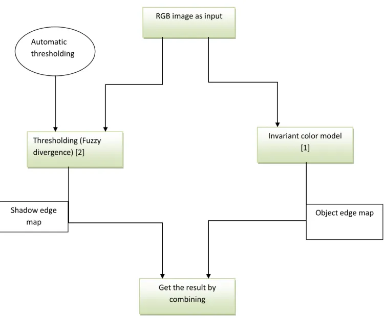
3. Proposed algorithm
Basically the proposed algorithm in this project is a hybrid algorithm for cast shadow detection in a still image. The program consists of two modules: thresholding and invariant color model.
RGB image as input
Thresholding (Fuzzy divergence) [2]
Invariant color model [1]
Automatic thresholding
Get the result by combining
Object edge map Shadow edge
map
20
For the second module i.e. invariant color model, which provides object edge map has not been modified. But for the first module i.e. thresholding, which is already implemented in another paper [2] is based on calculating minimum fuzzy divergence. It has been already discussed why this technique is used. So the first module provides the shadow edge map which consists both: self shadow and cast shadow region (Fig. 22.).
Initially a standard sample image is taken as input. Gray image of the sample is passed as argument to first module which returns optimum threshold value. Using that value the gray image is thresholded. Before applying Sobel operator to get shadow edge map isolated pixels are deselected using morphological operation. In this way more accurate shadow edge map is achieved.
In second module, RGB image is converted using C1C2C3 color model. Again that image is
passed into fuzzy function to get optimum threshold value. That value is used for thresholding. After thresholding to get better object edge map, at first morphological operation is done to remove isolated white pixels remaining inside the black region. If we apply Sobel operator directly, we will get many loops inside the edge map which will lead to much complexity to get the result. So after morphological operation, Sobel operator is used to get object edge map.
Once both edge maps have been got i.e. shadow edge map and object edge map then geometric property of shadow is used to get the result by manipulating both maps. For the first, the boundary of object map is required which is got by finding minimum and maximum values of X, Y coordinate of edges. Now, it is required to get the shadow line (Fig. 1.). So we need to remove all those pixels in the shadow edge map which are inside object edge map. The boundary condition geometrically represents a rectangular region. That rectangular box is superimposed
21
upon the shadow edge map and all pixels lying inside the region have been discarded, which produces shadow line. For now, the aim is to find hidden shadow line (Fig. 1.). Again boundary of shadow line is got. The rectangular box is superimposed upon object edge map. Whatever pixels are lying inside that box is selected. In this way cast shadow region is got but it is not closed region completely. To close the region, morphological operation is applied and finally we get the result, which is remapped on the sample image.
Steps required
The program consists of two modules:
1. Fuzzy() -
a. INPUT: gray image b. OUTPUT: threshold value 2. Sw_detection() -
a. INPUT: RGB image, threshold value b. OUTPUT: extracted cast shadow region
22
STEPS
I. The standard sample image is taken as input in the program (Fig. 17.).
II. Corresponding gray image is passed to fuzzy() function to find out threshold value (Fig. 18.).
III. Inside the fuzzy() function, the gray image is fuzzyfied and for each gray level
divergence value is calculated. For the minimum divergence value corresponding gray level is considered as threshold value. That value is returned to main program.
IV. Using that threshold value the input image is thresholded (Fig. 20.).
V. To discards isolated pixels in thresholded image morphological operations i.e. dilation, erosion are applied on it (Fig. 21.).
VI. Sobel operation is applied to get shadow edge map of image which consists of both cast shadow and self shadow region (Fig. 22.).
VII. Now using C1C2C3 color invariant feature, background and shadow region is suppressed
(Fig. 23.).
VIII. Gray image of Fig. 23. is again passed into fuzzy() function. Threshold value is returned. IX. Morphological operation is applied on Fig. 25.
X. Sobel operator is used to get object edge map (Fig. 27.).
XI. Now we have shadow edge map and object edge map (Fig. 22. & Fig. 27.).
XII. Find out the object edge map boundary and whatever pixels are within that region in shadow edge map are self shadow pixels, hence those are discarded and shadow line is got (Fig. 27.).
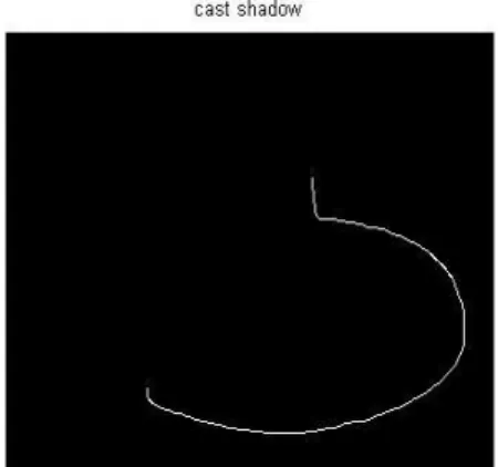
XIII. Again finding the boundary of shadow line and plotting all pixels lying in object edge map within the boundary we get hidden shadow line (Fig. 28.).
XIV. To close the cast shadow region morphological operation is applied (Fig. 29.).
XV. Finally remapping that region on original image with different color cast shadow region is extracted (Fig. 30.).
23
Results of steps
Fig. 17. Sample image Fig.18. Gray image of Orange
Fig. 19. Divergence vs. Gray level graph Fig. 20. Thresholded image of Orange for Gray image
24
Fig. 21. Threshold image after Fig. 22. Sobel edge map Morphological operation
Fig. 23. Result after using Invariant Fig.24. Divergence vs. Gray level graph color model for Fig. 23.
25
Fig. 25. Threshold image Fig. 26. After morphological operation of Fig. 23. on Fig. 25.
26
27
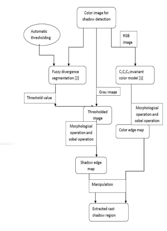
Block diagram
Fig. 31. Block diagram for cast shadow detection
28
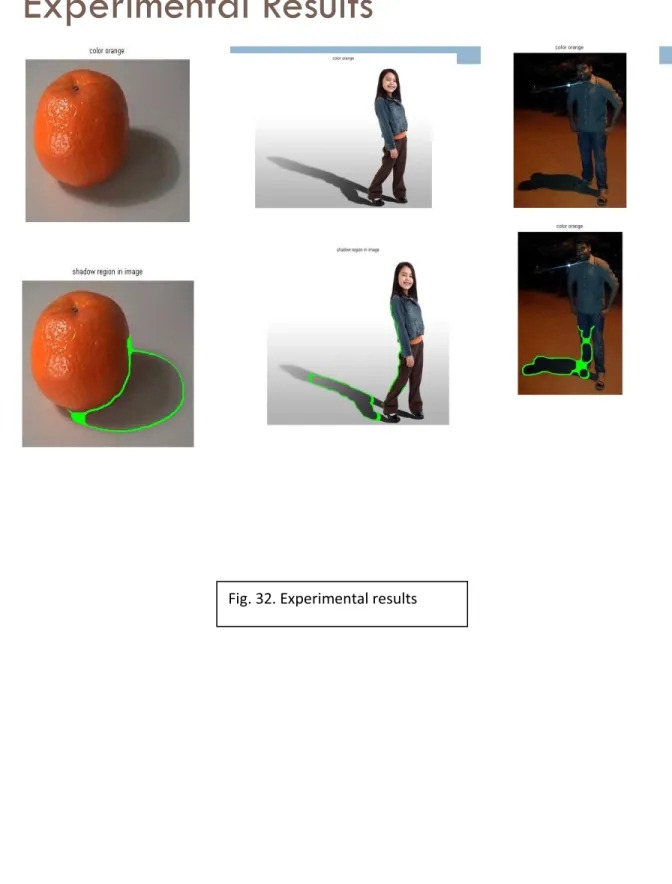
4. Experimental results
Experimental Results
29
5. Constraints
A. Objects should be of uniform color.
B. Only one light source illuminates the scene, and shadow and object are within the image. C. Light source must be strong enough.
D. Shadows are cast on a flat or nearly flat surface or non textured surface.
6. Conclusion
A novel hybrid approach is proposed to get better results which have been shown. In case of controlled environment good result has been produced i.e. for orange. But we can see that in case of non-uniform color image i.e. for girl some portion of body has been detected as shadow pixels. This is because of violation of those constraints. Still it has got appreciable results. While in case of last figure i.e. for night scene it has detected some of the leg portion as shadow. Noticeable thing is that it has detected shadow appropriately but due to bad light condition the dark portion of leg is also produced as shadow in the result by the program.
30
7. Future work
The proposed hybrid algorithm is working in case of controlled environment scenario. But for the implementation of shadow detection in real time system our first objective should be to reduce the number of constraints as mentioned previously so that it will produce results more accurately and precisely.
Another challenging future work in this field can be the situations when we have two light sources and getting two shadows for single objects. Generally these situations happen when we walk on the street in night and we get our two shadows because of continuous street lights standing from starting point to end point.
Finally we can implement this technique into an automated robot which will walk like a human being. It will find the path itself. If it encounters an obstacle, it will detect it and get alternate path. Similarly if it detects shadow, it will not bother and cross over it without deviating.
31
References
[1] Elena Salvador, Andrea Cavallaro, and Touradj Ebrahimia ,´Cast shadow segmentation using invariant color features´,in: Proc. Computer Vision and Image Understanding 95(2004) 238-259
[2] T. Chaira, A.K. Ray ,´Segmentation using fuzzy divergence´, in: Proc. Pattern Recognition Letters 24(2002) 1837-1844
[3] A. Huertas, R. Nevatia, ³Detecting buildings in aerial images´, Comput. Vis. Graph. Image Process. 41 (1988) 131±152.
[4] Y. Liow, T. Pavlidis, ³Use of shadows for extracting buildings in aerial images´, Comput. Vis. Graph. Image Process. 49 (1991) 242±277.
[5] A. Yoneyama, C.H. Yeh, C. C. J.Kuo, ³Moving cast shadow elimination for robust vehicle extraction based on 2d joint vehicle/shadow models´, in: Proc. IEEE Conf. on Advanced Video and Signal Based Surveillance (AVSS03), 2003.
[6] J.M. Scanlan, D.M. Chabries, R. Christiansen, ³A shadow detection and removal algorithm for 2-d images´, in: Proc. IEEE Int. Conf. on Acoustics, Speech, and Signal Processing (ICASSP), (1990)2057± 2060.
[7] G.S.K. Fung, N.H.C. Yung, G.K.H. Pang, A.H.S. Lai, ³Effective moving cast shadows detection for monocular color image sequences´, in: Proc. 11th Int. Conf. on Image Analysis and Processing (ICIAP), (2001)404±409.
[8] R. Cucchiara, C. Grana, M. Piccardi, A. Prati, ³Detecting objects, shadows and ghosts in video streams by exploiting color and motion information´, in: Proc. of 11th Int. Conf. on Image Analysis and Processing (ICIAP), (2001)360±365.
[9] C. Jiang, M.O. Ward, ³Shadow segmentation and classification in a constrained environment´, CVGIP: Image Understanding 59 (2) (1994) 213±225.
[10] T. Horprasert, D. Harwood, L.S. Davis, ³Statistical approach for real-time robust background subtraction and shadow detection´, in: Proc. IEEE Int. Conf. on Computer Vision, FRAME-RATE Workshop, 1999.
[11] O. Schreer, I. Feldmann, U. Goelz, P. Kauff, ³Fast and robust shadow detection in videoconference applications´, in: Proc. VIPromCom 2002, 4th EURASIP IEEE International Symposium on Video Processing and Multimedia Communications, (2002)371±375.
[12] R. Cucchiara, C. Grana, M. Piccardi, A. Prati, ³Detecting objects, shadows and ghosts in video streams by exploiting color and motion information´, in: Proc. of 11th Int. Conf. on Image Analysis and Processing (ICIAP), (2001)360±365.
32
[13] Rafael C. Gonzalez, Richard E. Woods, Steven, Digital Image Processing UsingMatlab 3Ed, Prentice Hall ©2004