Markus Pitk¨aranta
NETWORK ACCESS CONTROL BASED ON ENDPOINT INTEGRITY - INDUSTRY STANDARDS AND COMMERCIAL IMPLEMENTATIONS
Thesis submitted for examination for the degree of Master of Science in Technology Espoo 1.2.2010
Thesis supervisor:
Prof. Jukka Manner
Thesis instructor:
Author: Markus Pitk¨aranta
Title: Network Access Control Based on Endpoint Integrity - Industry Standards and Commercial Implementations
Date: 1.2.2010 Language: English Number of pages: 10+64 Department: Department of Communications and Networking
Professorship: Networking Technology Code: S-38
Supervisor: Prof. Jukka Manner
Instructor: Thomas G. Jørgensen, Ph.D.
Network security is an essential part of designing today’s corporate networks. Tradi-tionally security threats have been addressed by using network segmentation, firewalls, intrusion detection systems and so forth. However, most of the networks are still vulnerable to attacks coming from inside the internal network. Users in enterprise environments are becoming increasingly mobile when desktop computers are changing to portable computers and handheld devices. From a security perspective this poses new threats. The devices are moved outside the secure corporate network and connected to insecure networks in airports, hotels, caf´es, etc. Their security software that defends from malicious users might not be up to date which may expose the device to infection. When the device is connected back to the corporate environment, the whole network might become under threat.
Network Access Control based on Endpoint Integrity is a set of mechanisms to enforce security policies for network devices. The idea is that network access is granted only after certain compliance checks have been passed. Non-compliant endpoints can be denied access or they can be isolated into a dedicated network segment where they can be remediated. Remediation is the process where a non-compliant node is made compliant by applying necessary changes into configurations, installing the latest virus signatures, etc.
AALTO-YLIOPISTON TEKNILLINEN KORKEAKOULU DIPLOMITYON¨ TIIVISTELMA¨ Tekij¨a: Markus Pitk¨aranta
Ty¨on nimi: P¨a¨atelaitteen eheyteen pohjautuva verkon p¨a¨asynvalvonta - Teollisuusstandardit ja kaupalliset toteutukset
P¨aiv¨am¨a¨ar¨a: 1.2.2010 Kieli: Englanti Sivum¨a¨ar¨a: 10+64 Osasto: Tietoliikenne- ja tietoverkkotekniikan laitos
Professuuri: Tietoverkkotekniikka Koodi: S-38
Valvoja: Prof. Jukka Manner Ohjaaja: TkT Thomas G. Jørgensen
Tietoturva on keskeinen osa nykyaikaista verkkosuunnittelua. Perinteisesti tietoturvaa on pyritty parantamaan k¨aytt¨am¨all¨a mm. verkkojen segmentointia, palomuureja sek¨a erilaisia IDS/IPS-j¨arjestelmi¨a. Ongelma nykyp¨aiv¨an organisaatioissa on yh¨a enemm¨an ja enemm¨an liikkuvat k¨aytt¨aj¨at. Kannettavat tietokoneet ovat syrj¨aytt¨aneet perinteiset p¨oyt¨atietokoneet, mik¨a tuo uusia riskej¨a tietoturvan¨ak¨okulmasta sill¨a laitteet liikkuvat suojatun yritysverkon ulkopuolelle. K¨aytt¨av¨at kytkev¨at laitteita julkiseen verkkoon lentokent¨all¨a, kahviloissa sek¨a hotellien aulassa. Julkisissa verkoissa koneet altistuvat helpommin hy¨okk¨ayksille. Mik¨ali laitteen tietoturva-asetukset eiv¨at ole ajan tasalla tai esimerkiksi palomuuri on kytketty pois p¨a¨alt¨a, laite saattaa saada tartunnan. Siin¨a vaiheessa kun saastunut kone kytket¨a¨an takaisin yrityksen sis¨averkkoon, tartunta saattaa levit¨a koko verkon laajuisesti.
P¨a¨atelaitteen eheyteen pohjautuva verkon p¨a¨asynvalvonta on joukko mekanismeja, joiden avulla p¨a¨atelaitten tietoturva-asetukset voidaan pakottaa m¨a¨aritettyjen tietotur-vak¨ayt¨ant¨ojen mukaisiksi. Laitteen muodostaessa yhteyden verkkoon sille tehd¨a¨an ti-etyt tarkistukset, joiden pohjalta p¨a¨atet¨a¨an sallitaanko laitteen p¨a¨asy verkkoon. Laitteet, jotka eiv¨at vastaa tietoturvak¨ayt¨ant¨oj¨a, voidaan erist¨a¨a erilliseen karanteeniverkkoon, jossa laitteiden asetukset voidaan palauttaa k¨ayt¨ant¨ojen mukaisiksi esimerkiksi asenta-malla uusimmat virustunnisteet.
Avainsanat: Authentication, Authorization, Access Control, Trusted Network Con-nect
Preface
Integrity-based network access control has received a lot of attention during the last few years. This thesis was carried out to give a better understanding of the current status of the industry, and identify the key players in the market. The work was supported by Avanade which is a global IT consulting company specialized in Microsoft technologies.
I would like to thank my istructor Thomas G. Jørgensen for his constructive comments and contribution to this thesis. I will buy you a Tuborg the next time I am visiting Copenhagen.
Otaniemi, 1.2.2010
Contents
Abstract ii
Abstract (in Finnish) ii
Preface iv
Table of contents v
Abbreviations vii
1 Introduction 1
2 Industry Standards for NAC-EI 3
2.1 Background . . . 3
2.1.1 Trusted Network Connect (TNC) . . . 3
2.1.2 Network Endpoint Assessment (NEA) . . . 3
2.2 TNC Architecture . . . 5
2.3 TNC Layers . . . 6
2.4 TNC Entities and Components . . . 7
2.5 TNC Interfaces . . . 8
2.5.1 Integrity Measurement Collector Interface (IF-IMC) and Integrity Measurement Verifier Interface (IF-IMV) . . . 8
2.5.2 TNC Client-Server Interface (IF-TNCCS) . . . 11
2.5.3 Vendor-Specific IMC-IMV Messages (IF-M) . . . 14
2.5.4 Network Authorization Transport Protocol (IF-T) . . . 15
2.5.5 Policy Enforcement Point Interface (IF-PEP) . . . 21
2.5.6 Metadata Access Protocol (IF-MAP). . . 24
2.6 Phases in TNC . . . 28
2.7 TNC and the Trusted Platform Module . . . 30
2.8 Federated TNC . . . 31
2.9 Summary . . . 34
3 Commercial implementations of NAC-EI 36 3.1 Introduction . . . 36
3.3 NAP Client Architecture . . . 38
3.4 NAP Server Architecture . . . 39
3.5 NAP Enforcement Methods. . . 40
3.5.1 IPsec Enforcement . . . 41 3.5.2 IEEE 802.1X Enforcement . . . 43 3.5.3 DHCP Enforcement . . . 45 3.5.4 VPN Enforcement . . . 47 3.6 NAP and TNC. . . 48 3.7 Summary . . . 52 4 Future of NAC-EI 53 4.1 Status Quo. . . 53 4.2 Case Studies . . . 54 4.3 Prospective . . . 55 5 Conclusion 58 References 60
Abbreviations
Abbreviations
AAA Authentication, authorization and accounting
ACE Access Control Entity
ACL Access Control List
AD Active Directory
AIK Attestation Identity Key
API Application Programming Interface
AR Access Requestor
ASD Asserting Security Domain
CA Certificate Authority
CNAC Cisco Network Admission Control
CoA Change-of-Authorization
DHCP Dynamic Host Configuration Protocol
DNS Domain Name System
EAP Extensible Authentication Protocol
EAPOL EAP over LAN
EC Enforcement Client
EK Endorsement Key
ES Enforcement Server
HRA Health Registration Authority
IdP Identity Provider
IDS Intrusion Detection System IETF Internet Engineering Task Force IF-FTNC Federated TNC protocol
IF-IMC Integrity Measurement Collector Interface IF-IMV Integrity Measurement Verifier Interface IF-M Vendor-Specific IMC-IMV Messages IF-MAP Metadata Access Protocol
IF-PTS Platform Trust Services Interface
IF-T Network Authorization Transport Protocol IF-TNCCS TNC Client-Server Interface
IF-TNCCS-SOH IF-TNCCS bindings for Microsoft SoH protocol IMC Integrity Measurement Controller
IMV Integrity Measurement Verifier IPS Intrusion Prevention System IWG TCG Infrastructure Work Group
MAC Media Access Control
MAC Message Authentication Code
MAP Metadata Access Point
MAPC MAP Client
NAA Network Access Authority NAC Network Access Control
NAC-EI Network Access Control Based on Endpoint Integrity NAP Network Access Protection
NAR Network Access Requestor NEA Network Endpoint Assessment
NEA-WG Network Endpoint Assessment Working Group NPS Network Policy Server
OTP One-Time Password PA Posture Attribute Protocol PB Posture Broker Protocol
PCR Platform Configuration Register PDP Policy Decision Point
PEAP Protected EAP
PEP Policy Enforcement Point PKI Public Key Infrastructure PPP Point-to-Point Protocol
PPTP Point-to-Point Tunneling Protocol
PRA Provisioning and Remediation Application PRR Provisioning and Remediation Resource PT Posture Transport Protocol
PTS Platform Trust Services
RADIUS Remote Authentication Dial In User Service RSD Relying Security Domain
SAML Security Assertion Markup Language SHA System Health Agent
SHV System Health Validator
SKAE Subject Key Attestation Evidence SNAC Symantec Network Access Control SOAP Simple Object Access Protocol SoH Statement of Health
SoHR Statement of Health Response SP Service Provider
SPI Security Posture Information SSoH System Statement of Health
SSoHR System Statement of Health Response TCG Trusted Computing Group
TLS Transport Layer Security TLV Type-length-value
TNC Trusted Network Connect TNCC TNC Client
TNCS TNC Server
TPM Trusted Platform Module TS Terminal Server
TSS TCG Software Stack UAC Unified Access Control VLAN Virtual Local Area Network VPN Virtual Private Network VSA Vendor-Specific Attribute XML Extensible Markup Language
1
Introduction
Network Access Control (NAC) is a general terminology for mechanisms that are used in computer networks to restrict access to network resources based on security policies. The traditional methods of controlling access to a network have been authentication and authorization. Authentication is the process of verifying that the client is actually who it claims to be, and authorization means granting or denying access to resources, often based on identity information received from the authentication process.
In modern times computers have gotten increasingly mobile, which has led to new kinds of security threats from a networking perspective. Traditionally the biggest challenge of network operators has been blocking attacks from malicious clients by using such mecha-nisms as NAC described above and other network security mechamecha-nisms, such as network segmentation, firewalls and Intrusion Detection and Prevention Systems (IDS/IPS). The problem with these mechanisms is that they usually assume that the attack comes from a malicious client. The problem with mobile computers and users is that the computers are connected into public networks in airports, caf´es, etc. The clients usually have some kind of client security software installed to protect them from security threats. However there will be times when the client security software is turned off due to a user being frustrated by it consuming too many resources, or the operating system or software program on the client is out of date because it has not received the latest security updates. Any of these scenarios may lead into a situation where the client is exposed to security threats. If the client gets infected and then connects to the internal network, the infection may propagate to other clients within the network. In this situation the attack is coming from what seems to be a legitimate client. Internal networks are often considered more secure than public networks and the clients may be configured with less strict security settings which makes them vulnerable. This can even strengthen the possible impact of the infection on the network.
One possible resolution for the problems described above would be to make the access control decision based on the endpoint’s integrity or security posture. The integrity is a collection of security measurements that define the security state of the client, and these integrity measurements can be compared to a set of security policies predefined to decide whether the client is compliant and granted access to the network. Possible integrity measurements could include the state of a client firewall or antivirus software and whether the client’s operating system is up to date.
At the time of writing, there are several commercial products for integrity-based net-work access control. Such vendors as Cisco, Juniper, HP, Symantec and Microsoft have brought their solutions into market but currently the architecture lacks standardization which makes the implementations of different vendors unable to inter-operate. Trusted Computing Group (TCG) is a non-profit organization formed to promote vendor-neutral industry standards for secure computing [2]. TCG has developed an architecture for integrity-based network access control called Trusted Network Connect (TNC). TNC is an attempt at interoperability between the implementations of different vendors, but un-fortunately currently most of the implementations are not compatible with the TNC.
is a working group formed to agree standards for this area. IETF NEA has drafted a requirements document for reference architecture [4] and is going to solicit candidate protocol specifications and evaluate them as candidate specifications. Currently there are drafts for two of the protocols in the NEA reference architecture and they are derived from the TNC architecture.
The goal of this thesis is two-fold: The primary goal is to analyze how a current com-mercial implementation conforms to one of the proposed vendor-neutral standards. The secondary goal is to evaluate the future of Network Access Control Based on Endpoint Integrity (NAC-EI). Thus the starting point for this study is to describe an industry stan-dard architecture for NAC-EI and then compare it to a commercial implementation. The industry standard chosen for this study is the TNC architecture, because it is currently the most comprehensive standard available. Microsoft Network Access Protection (NAP) will be compared to TNC because NAP and TNC are claimed to interoperate [1]. Based on this analysis, an evaluation of the discussion of NAC-EI implementations is provided. The emphasis in this thesis is on the architectural design of the NAC-EI implementations. Thus the major achievement is to provide an overview of the two architectures described. TNC and NAP share a lot of similarities as evidenced by the comparison of these frame-works. This is not a coincidence as Microsoft is one of the contributors of the TNC Work Group. When analyzing the current market situation we saw that the main competing frameworks are the TNC and Cisco Network Admission Control (CNAC). The conclu-sion was that out of these two the TNC is becoming the leading framework for NAC-EI. The main reason for this is the fact that TNC is becoming an IETF standard.
This thesis is divided into three parts. Chapter 2 describes the TNC architecture in detail. In chapter 3 we evaluate the Microsoft NAP architecture and compare it to TNC. Chapter 4 provides a brief analysis of the future of NAC-EI standards and implementations.
2
Industry Standards for NAC-EI
This chapter presents an overview of current industry standards for Network Access trol based on Endpoint Integrity (NAC-EI). The chapter focuses on Trusted Network Con-nect (TNC) by describing the building blocks of the architecture.
2.1
Background
This section is an overview of the current industry standards and work groups defining architectures for NAC-EI.
2.1.1 Trusted Network Connect (TNC)
Trusted Computing Group is a non-profit organization founded in 2003 to develop and promote vendor-neutral open standards for computer security. The TCG has members and contributors from industry leading companies, such as Hewlett-Packard, IBM, Ju-niper and Microsoft. The standards involve hardware building blocks and software inter-face specifications across multiple hardware platforms and operating systems. The most widely implemented TCG standard is the Trusted Platform Module (TPM) which is a hardware module used for storing cryptographic keys. Most of today’s laptops, especially the ones designed for business users, have a TPM chip installed. The TPM has been also accepted as an ISO/IEC standard [27]. [2]
Trusted Network Connect (TNC) is an architecture developed by the TCG that enables access control based on endpoint integrity in addition to traditional authentication and authorization. The goal of TNC is to enable network operators to define policies regarding the security state of endpoints. The endpoint’s compliance with these security policies can then be used to determine whether to grant or deny access to a network resource. The TNC architecture will be described more granularly later in this study. [3]
2.1.2 Network Endpoint Assessment (NEA)
The Internet Engineering Task Force (IETF) is also working on standardizing protocols for NAC-EI. The architecture is referred as Network Endpoint Assessment (NEA) and the work group defining the architecture is Network Endpoint Assessment Working Group (NEA WG). NEA uses the term ”posture” to refer to the security state of an endpoint. The posture of an endpoint is derived from such information as hardware and software configuration including whether a software component installed to protect the endpoint (e.g., an anti-virus program or client firewall) is up-to-date. The goal of NEA is to provide a standard way of assessing the posture of an endpoint for the purpose of monitoring compliance to the posture policy of the organization. [4]
The NEA supports two deployment scenarios: advisory mode and mandatory mode. In advisory mode the endpoint is granted unrestricted access to the network regardless of the
result of the posture assessment. This deployment scenario can be used for just monitoring the posture of the endpoints. In mandatory mode the endpoint gains only restricted access to support remediation purposes, i.e. to bring the endpoint compliant with the posture policy. Defining mechanisms for providing restricted access is out of the scope of the NEA WG. [4]
Figure 1: NEA Reference Model [4]
Figure 1 describes the reference model for Network Endpoint Assessment. The NEA Client is comprised of three kinds of components: Posture Collectors, Posture Broker Client and Posture Transport Clients. These components communicate with their coun-terparts on the NEA Server. The Posture Collectors exchange posture information with the Posture Validators using the Posture Attribute Protocol (PA). The Posture Broker Client and Posture Broker Server multiplex and de-multiplex these messages and communicate with each other using the Posture Broker Protocol (PB). The Posture Transport Client is responsible for establishing a reliable communication channel with the NEA Server. There may be multiple Posture Transport Clients within a particular Posture Broker Client to support multiple protocols. Each Posture Transport Client communicates with a Pos-ture Transport Server using a PosPos-ture Transport Protocol (PT). Defining the PT is out of the scope of the NEA WG as there are existing protocols that can be used for the PT. The dashed lines in Figure1represent the Application Programming Interfaces (APIs) and/or protocols between the components within the NEA Client or NEA Server. Standardizing these interfaces is also out of scope of the NEA WG.
When standardizing the Posture Attribute Protocol and Posture Broker Protocol the NEA WG has recognized that there already exist several non-standard protocols that may fill
the requirements for the PA ad PB. Currently the NEA WG has accepted the IF-M and IF-TNCCS from the TNC architecture as candidate protocols [5] [6].
2.2
TNC Architecture
The Trusted Network Connect (TNC) architecture is based on the TCG Infrastructure Work Group (IWG) Reference Architecture for Interoperability which is an architecture aiming at improving interoperability between systems containing TCG technology [7]. One of the most important concepts in the architecture is Trusted Platform, which refers to hardware-protected platform authentication. In practice this is equivalent of using a Trusted Platform Module [27], which is a computer chip that can store securely artifacts that can be used for platform authenticaion.
The IWG Platform-Authentication model defines three entitites: Requestor, Verifier and Relying Party as depicted in Figure2. Requestor is the platform seeking to be authenti-catied by the verifier. The Requestor is performing a transaction with the Relying Party which relies on the Verifier to evaluate the statements issued by the Requestor. The Ver-ifier performs the evaluation of the Requestor’s statements based on some set of criteria or rules. One example of this kind of a network access control architecture is the IEEE 802.1X. In this example the requestor would be an 802.1X Supplicant, the relying party would be an 802.1X Authenticator (e.g., switch) and the verifier would be a 802.1X Au-thentication Server. [8] [3]
Figure 2: The IWG Platform-Authentication model
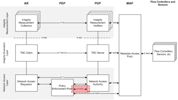
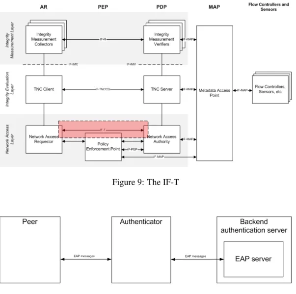
In the TNC architecture, the three main components are Access Requestor (AR), Policy Decision Point (PDP) and Policy Enforcement Point (PEP) as shown in Figure 3. The AR is equivalent to Requestor in the IWG Architecure, the PDP maps to Verifier and the PEP acts as the Relying Party. The naming convention is quite describing as the Access Requestor is the client requesting for access to the network. The Policy Decision Point is the party that makes the actual access decision, and Policy Enforcement Point is the component that enforces the decision made by the PDP. [3]
Figure4shows a more detailed view of the TNC Architecture. The entities are depicted by the five columns in the figure. The different entities are the Access Requestor (AR), the Policy Enforcement Point (PEP), the Policy Decision Point (PDP), the Metadata Access Point (MAP) and Flow Controllers and Sensors. The entities can be divided into three layers which distinguish different components within each entity. The interfaces between the components are depicted with the dashed lines and arrows.
Figure 3: A simplified view of the TNC Architecture
Figure 4: The TNC Architecture
2.3
TNC Layers
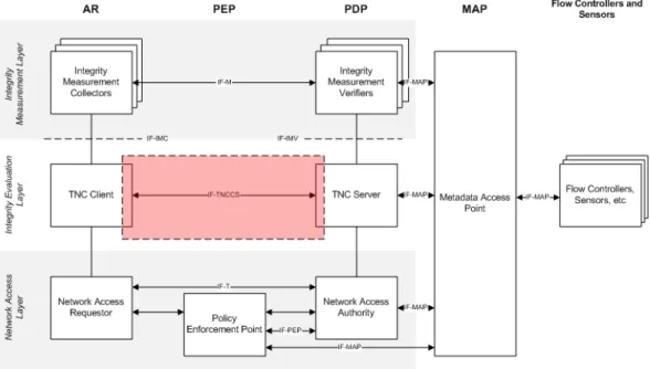
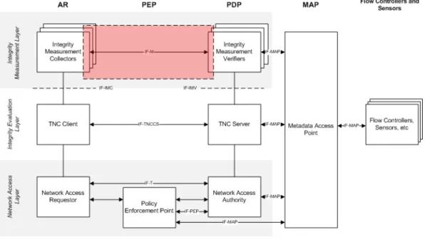
The TNC architecture divides into three layers: network access layer, integrity evaluation layer and integrity measurement layer. The network access layer is responsible for net-work connectivity. This can involve several netnet-work technologies such as Virtual Private Networking (VPN) and 802.1X. The three components within the network access layer are Network Access Requestor (NAR), Policy Enforcement Point (PEP) and Network Access Authority (NAA). [3]
The integrity evaluation layer contains components that are responsible for evaluating the overall integrity of the Access Requestor. The components on the integrity evaluation layer use the information received from the integrity measurement layer as input. The two components within the integrity evaluation layer are the TNC Client and the TNC Server. The integrity measurement layer contains the components that collect and verify integrity information, i.e., Integrity Measurement Collectors (IMCs) and Integrity Measurement Verifiers (IMVs). [3]
2.4
TNC Entities and Components
The entities and components in the TNC Architecture are logical, not physical. A com-ponent or an entity may be a software program, a physical device or a replicated set of machines to serve redundancy. The entities can be divided into required entities and op-tional entities. The required entities are the Access Requestor (AR) and the Policy Deci-sion Point (PDP). The optional entities are the Policy Enforcement Point (PEP), Metadata Access Point (MAP), and Flow Controllers and Sensors. [3]
Access Requestor (AR) is the entity seeking access to a protected network in order to con-duct activities in the network. The AR consists of three components: Network Access Re-questor (NAR), TNC Client (TNCC) and Integrity Measurement Collector (IMC). NAR is the component responsible for establishing network access with the PEP and PDP. There may be several NARs within a single AR to support various connection mechanisms. Examples of NARs include VPN client software and IEEE 802.1X client. [3]
The TNCC is a software component that aggregates the integrity measurement informa-tion received from the IMCs and communicates the integrity state of the client to the TNC Server. There may be multiple IMCs within an AR and each IMC measures some aspect of the endpoint posture. For example, one IMC can check the status of a client anti-virus software while another IMC may check that the operating system has the latest security updates installed. Because this kind of information often depend on the implementation, vendors can implement their own IMCs to provide that kind of integrity measurements. [3]
Policy Decision Point (PDP) makes the decision regarding the Access Requestor’s net-work access request. The decision is made using the integrity information provided by the AR and a predefined set of security policies. The PDP consists of three components: Network Access Authority (NAA), TNC Server (TNCS) and Integrity Measurement Ver-ifier (IMV). The NAA is the component that decides whether the AR should be granted or denied access to the network. The NAA makes the decision based on the information it gets from the TNCS. [3]
The TNCS is the component that manages the communication between the IMCs and IMVs. The TNCS aggregates the Action Recommendations from the IMVs and combines them into an overall Action Recommendation and sends it to the NAA. The IMV is a software component that verifies some aspect of the integrity of the client. [3]
Policy Enforcement Point (PEP) is the name of the entity and component that executes the network access decision made by the PDP. This decision might be to allow unrestricted access to the network for the AR, to allow only restricted access, or to deny access. Exam-ples of Policy Enforcement Points include network devices such as switches or wireless access points.[3]
Metadata Access Point (MAP) is the name of the entity and component that allows other components to publish, subscribe and query information about the integrity state of the ARs. This allows components such as flow controllers and sensors to use the integrity information, as well as other information about the endpoints. [3]
Flow controllers are components that control the flows in the network based on infor-mation obtained from the MAP. Examples of flow controllers include firewalls and rate limiters that can block or limit the network traffic originated from or destined for a par-ticular endpoint or user. Sensors are components that publish information about network activities to the Metadata Access Point. Examples of such activities include an endpoint accessing certain services in the network, authentication activities and broadcast messages for services (e.g., DHCP). [3]
2.5
TNC Interfaces
This section describes the interfaces and protocols defined in the TNC architecture. 2.5.1 Integrity Measurement Collector Interface (IF-IMC) and Integrity
Measure-ment Verifier Interface (IF-IMV)
Integrity Measurement Collector Interface (IF-IMC) is the interface between the Integrity Measurement Collectors and the TNC Client as depicted in Figure5. Using the IF-IMC, the TNC Client can collect integrity measurement information from the IMCs. The IF-IMC is closely related to Integrity Measurement Verifier Interface (IF-IMV) which is the interface between the Integrity Measurement Verifiers and the TNC Server.[9] [10]
Figure 5: The IF-IMC and IF-IMV The supported use cases for IF-IMC[9]:
• A TNCC and one or more IMCs that support the same platform binding have been installed on an endpoint. The TNCC finds and loads the IMCs. Then it runs one
or more Integrity Check Handshakes. The IMCs and TNCC may use any of the features of IF-IMC.
• A TNCC that supports the Java Platform Binding has restricted privileges/permissions (as when loaded into a sandbox in a web browser). It loads IMCs that support the Java Platform Binding and runs one or more Integrity Check Handshakes. The IMCs may actually have greater privileges than the TNCC (or they may not be sandboxed).
• A TNCC that supports the Java Platform Binding runs with generous privileges but chooses to run IMCs with restricted privileges for security reasons. It loads IMCs and runs one or more Integrity Check Handshakes.
• A TNCC is running on an endpoint. When an IMC is installed or uninstalled, the TNCC notices this and loads or unloads the IMC.
The supported use cases for IF-IMV are [10]:
• An IMV and TNCS that support the same platform binding are installed on an endpoint. The TNCS finds and loads the IMV. Then it runs one or more Integrity Check Handshakes. The IMV and TNCS may use any of the features of IF-IMV.
• A TNCS has restricted privileges. It loads IMVs and runs one or more Integrity Check Handshakes.
• A TNCS that supports the Java Platform Binding runs with generous privileges but chooses to run IMVs with restricted privileges for security reasons. It loads IMVs and runs one or more Integrity Check Handshakes.
• An IMV and a TNCS both support the reason string extensions to IF-IMV. An IMV provides a reason string to a TNCS, giving the reason for its IMV Action Recommendation. The TNCS logs this reason and/or passes it on to the TNCC through an extension to IF-TNCCS. At the TNCC, the reason information may be displayed to the user (perhaps in a detailed view). The reason string may be in the endpoint user’s preferred language or (if that language is not available) in another language.
• A TNCS is running. When an IMV is installed or uninstalled, the TNCC notices this and loads or unloads the IMV.
IF-IMC and IF-IMV contain the following features: Integrity Check Handshake, Connec-tion Management, RemediaConnec-tion and Handshake Retry, Message Delivery and Batches. Integrity Check Handshake is the context that IMCs and IMVs use to exchange messages with each other. This is a very important functionality as this enables IMVs to become aware of the security state of the IMCs. This information exchange is the foundation for the access control decision made by the PDP. In the Integrity Check Handshake the IMCs send a batch of messages to the IMVs, and the IMVs may respond with a batch of mes-sages. The response may contain queries for more information, remediation instructions,
etc. In the end of this dialog the IMVs make their decision on their IMV Action Rec-ommendations. Several Integrity Check Handshakes may occur between a TNCC and a TNCS. The first handshake may end with the client receiving remediation instructions to become compliant. After the remediation another handshake is performed to prove the clients compliance, and subsequent handshakes might occur e.g., in the case of a policy change. For a given TNCC-TNCS pair one handshake must always end before another one begins. [9] [10]
The TNCC maintains the connection state by using a connection ID, which is an identifier chosen when the connection is established. The connection ID is completely local for the TNCC, so it is not shared with the TNCS. When a new network connection is established the TNCC notifies the IMCs of the new connection and informs them if the state of the connection is changed. When the connection ends the TNCC informs the IMCs that the connection is terminated and that the connection ID will be deleted. However, the TNCC should use the same connection ID while communicating with the same TNCS. This allows the TNCC to request a handshake retry for an earlier connection, e.g., after it has completed remediation. The remediation might require restarting the operating system or power cycling, so the connection ID should be retained even during these operations in order to be able to request the handshake retry. [9] [10]
There are a few scenarios when it is desirable to retry the Integrity Check Handshake without establishing a new network connection with a new connection ID. If an endpoint has been isolated and and then remediated an IMC can suggest the TNCC to retry the Integrity Check Handshake with the existing connection ID without establishing a new connection. The TNCS can also initiate a handshake retry as a result of a security policy change or as a periodic activity. And finally, an IMC or IMV can request a handshake retry in response to a condition detected by the IMC or IMV. [9]
The network access decision in the TNC architecture is based on information exchange between IMCs and IMVs. That is why the message delivery between IMCs and IMVs a critical function for the architecture. IF-IMC includes functions for sending and receiving those messages. The message itself consists of a message body, a message type, and a recipient type. The message body is sequence of bytes. The message type is a number that uniquely defines the structure and semantics of the message body. The recipient type is simply a flag that indicates whether the recipient is an IMC or an IMV. The TNCC and TNCS should not parse the message body as it is done by the IMCs and IMVs. The IMCs and IMVs announce to the TNCC and TNCS which message types they want to receive. The TNCC and TNCS use the message type and recipient type to route the message to correct recipient or recipients. [9] [10]
The messages between IMCs and IMVs are always carried over in batches. This is due to the fact that these messages are often carried over protocols like Extensible Authentication Protocol (EAP) that require endpoints to take turns in sending messages i.e., only one endpoint can send at the time. The first batch of messages is always sent by the IMC. The IMV can respond to these messages and the IMCs can respond to the messages sent by the IMV. This way the dialog goes on until the handshake is over. [9] [10]
2.5.2 TNC Client-Server Interface (IF-TNCCS)
The IF-TNCCS defines a protocol for exchanging messages between the TNC Client and TNC Server as described in Figure6. The types of messages include [11]:
• Messages from IMCs to IMVs (e.g., integrity measurements)
• Messages from IMVs to IMCs (e.g., remediation instructions or requests for addi-tional measurements)
• Messages from TNCCs to TNCSs (e.g., control messages)
• Messages from TNCSs to TNCCs (e.g., TNCCS-Recommendation message)
Figure 6: The IF-TNCCS Supported use cases for IF-TNCCS are:
• The messages sent from IMCs to IMVs during the the Integrity Check Handshake are carried through IF-TNCCS.
• During the Integrity Check Handshake the IMVs may optionally respond to the IMCs (e.g., remediation instructions). These messages are carried through IF-TNCCS.
• The TNCC may send a batch of messages to the TNCS by using IF-TNCCS. These messages can be either standardize or vendor-specific.
• The TNCS may send a batch of messages to the TNCC by using IF-TNCCS. These messages can be either standardize or vendor-specific.
• IMVs may provide a reason string describing the reason for their IMV Action Rec-ommendations. The TNCS may pass these reason strings to the TNCC by using an extension to IF-TNCCS.
• The TNCS may inform the TNCC of its IP address and port number.
One of the primary functions of IF-TNCCS is to facilitate message exchanges between the IMCs and IMVs so that the IMVs can TNC Server can assess the security state of the TNC Client. The communication between the IMCs and IMVs is always performed within the context of an Integrity Check Handshake, which was described earlier in context of the IF-IMC and IF-IMV. [11]
The messages exchanged between the TNC Client and TNC Server contain a message type, which is a four octet number uniquely identifying the format and semantics of the message. To ensure uniqueness the message type is formed from a vendor ID and a message subtype. The first three octets reflect the vendor ID, and the last octet describes a vendor-chosen message subtype. SMI Private Enterprise Numbers are used to provide the vendor IDs [14]. [11]
The IF-TNCCS contains a set of standardized TNCC-TNCS messages. These messages are listed in table1. All the standardized messages have the vendor ID of zero.
Table 1: TCG Standardized TNCC-TNCS Messages [11]
Message Type Value
TNCCS-Recommendation 0x00000001
TNCCS-Error 0x00000002
TNCCS-PreferredLanguage 0x00000003 TNCCS-ReasonStrings 0x00000004 TNCCS-TNCSContactInfo 0x00000005
The TNC Server sends a TNCCS-Recommendation to inform the TNC Client that the Integrity Check Handshake has completed and that the TNCS is ready to provide the TNCS Action Recommendation (allowed, isolated or none) for the NAA. The TNCCS Action Recommendation is included in the message. As the name implies, it is only a recommendation, and the NAA may ignore the decision made by the TNC Server and apply a different level of access. [11]
A TNCCS-Error message is sent when there has been a problem with the previous batch of messages. If the error message is sent from a TNC Client to the TNC Server then it must be in a batch that doesn’t contain any IMC-IMV messages. If it’s sent from the TNC Server to the TNC Client it must be placed into the same batch with the TNCS Action Recommendation message. [11]
The TNC Client can send a TNCCS-PreferredLanguage to indicate its preferred lan-guage to be used. This information is particularly useful when the IMV sends its rea-son strings to the TNC Server subsequently to the TNC Client. The rearea-son strings are included in a TNCCS-ReasonStrings message, which is sent from the TNC Server to the
TNC Client to explain the reason of the TNCS Action Recommendation. The TNCCS-PreferredLanguage can contain multiple reason strings each of which should be tagged with an RFC 3066 language tag [12] to indicate the language used. [11]
At the end of a successful assessment the TNC Server can use a TNCCS-TNCSContactInfo message to inform the TNC Client of its IP address and port number. The TNC Client can use this information to contact the TNC Server over L3 after it has been granted access to the network. The use of TNCCS-TNCSContactInfo supports and enables the use if IF-T over TLS [26] where the TNC Client is provided the IP address and port number of the TNC Server during a layer 2 IF-T assessment and then uses that address and port number to connect to the TNC Server. [11]
The messages between IMCs and IMVs are routed using two fields in the message: mes-sage type and recipient type. Each IMC and IMV indicates which mesmes-sage types it wants to receive. The TNCC and TNCS delivers the messages to those IMCs and IMVs that have the recipient type and corresponding to the recipient type of the message and that have announced to be willing to receive messages with the message type of the message. [11]
The IMC-IMV and TNCC-TNCS messages are always sent in batches. The Integrity Check Handshake starts with a batch of messages sent by the TNC Client to the TNC Server. The IMC-IMV messages are delivered to the IMVs that have registered for the corresponding message types. The TNCC-TNCS messages are parsed by the TNCS. If the IMVs or the TNCS want to response to the messages received, the TNCS gathers these messages into a batch and sends it to the TNCC. Again, the TNCC delivers the IMC-IMV messages to the corresponding IMCs and pops any TNCC-TNCS messages. This dialog goes on until the handshake is completed. If none of the IMCs want to send a message in a particular batch batch the TNCC will complete the handshake by sending a batch containing no IMC-IMV messages. This indicates to the TNCS that the TNCC has no more measurements to provide and that it wants to complete the handshake. Similarly, if none of the IMVs have messages to send in a batch, this indicates to the TNCS that the IMVs are ready to give their IMV Action Recommendations. The TNCS gathers these recommendatios into a TNCS Action Recommendations which is sent to the TNCC in a batch containing no IMC-IMV messages. [11]
If the TNC Server receives a malformed batch, or has an internal error, it should discard the batch and generate a TNCCS-Recommendation message containing a TNCCS-Error message and send it to the TNC Client. Similarly, if a TNC Client receives a malformed batch, or has an internal error, it should send a TNCCS-Error message to the TNC Server. When the TNC Server receives the Error message, it should generate a TNCCS-Recommendation message. [11]
TNCCS is based on Extensible Markup Language (XML) and the format of the IF-TNCCS messages is defined in the IF-IF-TNCCS schema [11]. In addition the TNC-WG has defined IF-TNCCS bindings for Statement of Health (SOH) protocol used by Microsoft Network Access Protection (NAP). The goal is to enable interoperability between NAP and systems based on the TNC architecture. [13]
2.5.3 Vendor-Specific IMC-IMV Messages (IF-M)
IF-M refers to the vendor-specific information exchange between IMCs and IMVs as depicted in Figure 7. IF-M is an application level protocol that carries Integrity Check Handshake messages between IMCs and IMVs. The IF-M allows IMCs to send mea-surement information about the local platform to IMVs for evaluation. The IMVs use IF-M for requesting more measurement information or sending their IMV Action Rec-ommendation to the client side. The recRec-ommendation may also contain instructions for remediation. The TCG will standardize certain widely used IF-M messages, but most of the messages will be specific to each IMC-IMV pair, i.e., vendor-specific. [22]
Figure 7: The IF-M
Table 2: IF-M Component Types [22]
Component Name Description
Reserved Reserved for use in specification
exam-ples, experimentation and testing. Operating System Operating system running on the
end-point
Anti-Virus Host-based anti-virus software
Anti-Spyware Host-based anti-spyware software
Anti-Malware Host-based anti-malware software
Firewall Host-based firewall
Intrusion Detection / Prevention (IDS/IPS) Host-based intrusion detection / preven-tion software
Virtual Private Networking (VPN) Host-based VPN software
end-to-end delivery to subscribed IMCs and IMVs. IF-TNCCS allows an IMC or IMV to subscribe for a particular type of message indicating that the IMC or IMV is willing to receive messages of that particular type. The message type indicates the software component that is associated with the information contained in the IF-M message and it is used by the TNCC and TNCS to route the messages to the IMCs and IMVs. The message type is comprised of a Vendor ID and a message subtype. Table 2 lists the message subtypes (i.e., component types) currently standardized by the TCG. [22]
Figure 8: An IF-TNCCS batch containing an IF-M message [22]
Figure8 depicts an TNCCS batch containing one or more M messages. Each IF-M message consists of a message header followed by zero or more assessment attributes. The IF-M message header and the header for each of the attributes use a fixed type-length-value (TLV) format.
2.5.4 Network Authorization Transport Protocol (IF-T)
Network Authorization Transport Protocol (IF-T) pertains to the message exchange be-tween the Network Access Requestor and Network Access Authority. The TNC is not standardizing IF-T as its own protocol, but provides bindings how to carry these messages over existing lower layer protocols such as Extensible Authentication Protocol (EAP) [15] or Transport Layer Security (TLS) [18]. [3]
Extensible Authentication Protocol (EAP) is an authentication framework that provides an infrastructure for network access clients and authentication servers to host plug-in modules for existing and future authentication methods. EAP was originally developed as an extension to Point-to-Point Protocol (PPP) [17] to support multiple authentication mechanisms without having to pre-negotiate the mechanism during the link establishment phase [15]. EAP is widely used in wireless networks but its support is not limited to wireless networks. The IEEE 802.1X [8] authentication mechanism is based on EAP.
Figure 9: The IF-T
Figure 10: Extensible Authentication Protocol
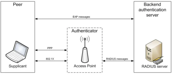
The three entities participating in EAP authentication are the authenticator, the peer and the authentication server which is often also referred as EAP server. The relation between these entities is depicted in Figure10. Peer is entity seeking access to a network. In IEEE 802.1X the peer is called the supplicant. Authenticator is the entity requiring the peer to authenticate before gaining access to the network. The authentication server authen-ticates the peer and provides authentication information to the authenticator. In the case where no backend authentication server is used, the authentication server is part of the authenticator. Buf often the authenticator will send authentication decisions to a backend authentication server in which case the authenticator is operating in pass-through mode. One protocol used to relay EAP messages between the authenticator and authentication server is RADIUS [16]. Figure11 depicts IEEE 802.1X authentication using RADIUS authentication server. [15] [8]
be-gins when the Authenticator sends a Request to the Peer. The Request packet contains a Type field which indicates the type of data being carried. The Type field may indicate authentication mechanism to be used, or it may carry some other information (e.g., dec-lination of a proposed authentication mechanism). The EAP specification defines three authentication types: MD5-Challenge [19], One-Time Password (OTP) [20] and Generic Token Card (GTC). EAP is not limited to theses authentication methods but additional authentication types may be defined. IETF has made a specification of using TLS within EAP [21], and vendors may also define their own authentication types, or plug-in modules to be used within EAP. Multiple authentication methods during an EAP conversation are not supported. But this can be achieved by utilizing a single EAP method and running other methods within it. This is referred as EAP tunneling. [15]
Figure 11: IEEE 802.1X
The TCG has defined protocol bindings for using IF-T over tunneled EAP methods. There are a number of tunneled EAP methods that have been implemented by different vendors. A tunneled EAP method consists of two phases: during the first phase a TLS tunnel is created over EAP, and during the second phase other information is carried over the protected TLS tunnel. The method providing the tunnels is referred as outer method, and the method that is used over the tunnel is called inner method. The function of these tunneled EAP methods is to provide a secure channel for exchanging other authentication and authorization information. By using tunneled EAP methods otherwise insecure EAP methods can be used securely as inner methods, as long as the outer method meets the security requirements. [23]
Figure 12 describes the protocol layers that combine to provide IF-T using tunneled EAP methods. The AAA Server refers to Authentication, Authorization and Accounting Server, which is a general term for a server that controls access to computer resources. The highlighted area indicates the layers that have components that are part of the IF-T protocol binding for tunneled EAP methods. EAP-TNC is a simple EAP method that is used as inner method in the dialog. EAP-TNC encapsulates IF-TNCCS messages they
can be carried over tunneled EAP methods. The EAP-TNC can be carried over any EAP tunneled method as long as both the peer and the authenticator use the same EAP method and implement the conform to the same EAP-TNC standard. This allows a peer from one tunneled method vendor to communicate with an authenticator from a diffenrent vedor. [23]
Figure 12: EAP-TNC and EAP Protocol Layers [23]
The Access Client and Protocol Translator initiate the access control dialog by using an access protocol. The Protocol Translator can be a wireless access point, a switch, etc. Examples of access protocols include IEEE 802.1X and IKEv2 [24]. The Protocol Translator and AAA Server exchange messages using an AAA protocol. Examples of AAA protocols include RADIUS and Diameter [25]. There is no limitation for using certain access or AAA protocols, as long as they support EAP authentication. Figure 13 shows how the messages are encapsulated using different protocols. The Protocol Translator removes the Access Protocol headers (e.g., 802.1X or IKEv2) and forwards the EAP message to the NAA using an AAA protocol (e.g., RADIUS). [23]
The TCG also has also defined protocol bindings for using IF-T over TLS. Earlier was described how EAP can be used to carry the assessment information prior to actually connecting to the network, i.e., getting an IP address. In this case the assessment needs to be carried within the protocol that is used during the joining process. But if the client already has an IP address then it can utilize higher layer protocols such as TLS to carry the assessment information. [26]
TLS is a protocol that allows applications to communicate across a network securely. TLS provides authentication, confidentiality and data integrity and it is widely adopted in many services including web servers and e-mail. The TLS protocol is composed of two layers.
Figure 13: IF-T protocol encapsulation [23]
TLS Record Protocol is the lower level component that operates on top of TCP or some other reliable transport protocol. The TLS Record Protocol provides data privacy and integrity. Data privacy is provided using symmetric cryptography (e.g., AES or RC4). The symmetric encryption keys are negotiated using another protocol (e.g., TLS Handshake Protocol). Data integrity is provided using Message Authentication Codes (MAC). The TLS Record Protocol is used for encapsulating higher-level protocols. The current TLS specification defines four content types or protocols that can be used on top of the Record Protocol: the Handshake Protocol, the Alert Protocol, the Change Cipher Spec Protocol, and the Application Data Protocol. TLS Handshake Protocol allows the endpoints to authenticate each other and negotiate encryption algorithms and symmetric encryption keys before the application starts transmitting data. The endpoints can be authenticated by using public key cryptography (e.g., RSA or DSA) or with shared secrets (TLS-PSK). The TLS Alert Protocol is used for informing the other endpoint of errors or warnings and the TLS Change Cipher Spec Protocol is used for changing ciphering parameters. The TLS Application Data Protocol refers to the content type that is used for the data of the application that is used on top of TLS. [18]
TLS provides very different connection properties than EAP because it provides a reliable connection that can carry high data volumes as opposed to EAP which is designed to support only small amounts of payload data. IF-T is used on top of TLS as an application which means that IF-T is encapsulated within the TLS Record Protocol using application data content type. [26]
The IF-T binding to TLS allows for either the TNC Client or TNC Server to establish the TLS session and initiate the assessment process. Examples of situations where either the TNC Client or TNC Server might initiate the assessment include:
• The TNC Server notices suspicious behavior on an endpoint
• The TNC Server receives new security policies that require reassessment of the TNC Client
• The TNC Client notices a change in its local security posture
• The TNC Client wants access to a protected network resource
Because either endpoint may initiate the TLS session, it means that both the TNC Client and the TNC server need to be listening to a TCP port that is known by the other party. When the TNC Server is the initiator, the TNC Client is effectively acting as the TLS server which means that the TNC Client should also possess an X.509 certificate that is used to protect the initial portion of the TLS handshake. Provisioning X.509 certificates to all TNC Clients requires a quite heavy Public Key Infrastructure (PKI) which is one of the reasons that it is actually recommended for the TNC Client not to listen for connec-tion requests coming from the TNC Server. Instead, the TNC Client should proactively establish and maintain a TLS session to the TNC Server so that either party may initiate the assessment process over the existing TLS session. [26]
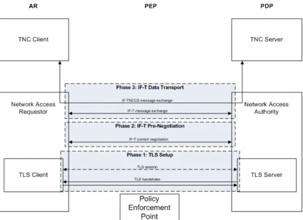
The IF-T over TLS message exchange occurs in three phases: TLS Setup, IF-T Pre-Negotiation and IF-T Data Transport. During the TLS Setup phase the TLS session ini-tiator (usually the TNC Client) establishes a TCP connection between the NAR and NAA. After the TCP connection is established the TLS Handshake Protocol is used for nego-tiating the cryptographic settings for the TLS session. During the negotiation the TLS session responder (usually the TNC Server) provides a trustworthy X.509 certificate that is used for authenticating the TLS responder. The TLS initiator may also provide a client certificate to authenticate to the TLS responder. If the client supports X.509 certificate with Subject Key Attestation Evidence (SKAE) [28] extensions it can be used in con-junction with a Trusted Platform Module (TPM) [27] to provide hardware-based platform authentication. Using TNC with TPM is described in section 2.7. After the TLS hand-shake the NAR and NAA have a protected session to exchange messages which allows the protocol to transition to the IF-T Pre-Negotiation phase. [26]
The IF-T Pre-Negotiation phase is performed only once during the lifetime of a TLS ses-sion. This phase is used for the NAR and NAA to discover each other’s IF-T capabilities and establish a context that will be kept intact during the lifetime of the TLS session. The context is basically the version of the IF-T protocol to be used. If client side authenti-cation has not been performed during the TLS handshake the NAA can authenticate the client during the IF-T Pre-Negotiation phase using IF-T client authentication messages (see table3. Finally the IF-T session transitions into IF-T Data Transport phase, where it remains for the lifetime of the session. [26]
During the Data Transport phase TNCCS messages are exchanged encapsulated in IF-T messages. Because of the full-duplex nature of the underlying IF-TLS session, either NAA or NAR may start transmitting an IF-TNCCS message received from its upper layer com-ponent (TNC Client or TNC Server). The initiator encapsulates the IF-TNCCS message in an IF-T message, assigns a message identifier to the message, and forwards it to the
Table 3: IF-T Message Types [26]
Message Type Contents
IFT TYPE EXPERIMENT Reserved for experimental use.
IFT VERSION REQUEST A version negotiation request including the ver-sions supported by the sender.
IFT VERSION RESPONSE Contains the IF-T version selected by the respon-der.
IFT CLIENT AUTH REQUEST Contains the authentication methods that the TNC Server supports and includes a request to choose an authentication method supported by the TNC Client.
IFT CLIENT AUTH SELECTION Contains the authentication method chosen by the TNC Client.
IFT CLIENT AUTH CHALLENGE Contains the authentication challenge sent by the TNC Server to the TNC Client.
IFT CLIENT AUTH RESPONSE Contains the client’s response to the authentica-tion challenge.
IFT CLIENT AUTH SUCCESS Indicates that the client was authenticated suc-cessfully.
IFT TNCCS 20 BATCH Contains an IF-TNCCS 2.0 message. IFT TNCCS SOH 10 BATCH Contains an IF-TNCCS 1.0 message.
IFT TNCCS XML 10 BATCH Contains an XML-based IF-TNCCS message.
IFT ERROR Contains an IF-T Error Message.
IFT NON TNC DATA Contains non-TNC standard application data. This can be used by applications that share the same TLS session but do not want to define a vendor-specific message type to identify the mes-sage.
responder. The responder decouples the IF-TNCCS message and forwards it to its upper layer component. [26]
Figure 14 depicts the three phases of an IF-T session and the message exchange that occurs within each phase.
2.5.5 Policy Enforcement Point Interface (IF-PEP)
IF-PEP protocol is used for sending network access decisions from the NAA to the PEP as depicted in Figure15. This occurs after the endpoint integrity has been assessed and the NAA has decided the level of access granted to the AR. The access decision triggers an action on the PEP, either to grant full access for the endpoint or to isolate the endpoint. There are two possible types of isolation: no access and limited access. The limited access can be used to provide remediation services for the endpoint. [29]
Figure 14: IF-T session phases
IF-PEP defines three isolation methods: binary-based, VLAN-based and filter-based iso-lation. Binary-based isolation is the simplest isolation technique in which the endpoint is either granted full access or it is completely blocked from the network. Binary-based iso-lation is straightforward to implement but it doesn’t support remediation of non-compliant endpoints. In Local Area Networks (LANs) that support IEEE 802.1Q [30] and 802.1D [31], virtual LANs (VLANs) can be used to provide isolation. VLANs allow network operators to divide physical Ethernet-based network into multiple logical networks and it is a technique originally used for improving network performance and scalability. Later it has been widely adopted also as a network security mechanism providing higher level of security between network segments within a physical network. In 802.1Q each Ether-net frame is tagged with a VLAN identifier, or tag, which identifies the logical Ether-network in which the frame belongs to. In VLAN-based isolation The PEP (an 802.1Q-capable switch) assigns tag for the endpoint’s traffic based on the network access decision made by the NAA. This allows defining different levels of access. For example, non-compliant endpoints may be isolated into a logical network (VLAN) that contains only necessary services to provide remediation for the endpoint. [29]
In filter-based isolation the network traffic of the AR is filtered by the PEP using Access Control Lists (ACLs). The ACLs consist of Access Control Entities (ACEs) each of which defines either a permit or deny rule for a service. The PEP evaluates an incoming packet against the ACLs to either allow or block the packet. In filter-based isolation the ACLs are generated based on the integrity state of the endpoint. This allows a granular way of
Figure 15: The IF-PEP
isolating the endpoint as it can be allowed to communicate only with specific IP addresses and TCP ports. It allows also isolation from other isolated endpoints even if they reside on the same IP subnet, which is not possible to achieve using VLAN-based isolation. [29] Using RADIUS as IF-PEP protocol is depicted in Figure 16. Implementation of the isolation techniques described earlier is quite straightforward using RADIUS. Binary-based isolation is natively supported by RADIUS by using the ACCESS-ACCEPT and REJECT messages [16]. The NAA responds to the PEP with an ACCEPT message when the endpoint should be given access, and with an ACCESS-REJECT when the endpoint should be blocked. For example, if the outcome of the as-sessment is that the AR is not compliant with the integrity requirements the NAA may prevent it accessing the network by responding to the PEP with an ACCESS-REJECT message. And similarly, if the AR is compliant the NAA responds with an ACCESS-ACCEPT message. [29]
There are a few options to provide VLAN-based isolation using RADIUS depending whether tagged or untagged VLANs are being used. When tagged VLANs are used the logical networks are differentiated using 802.1Q tags which allows multiple network in-terfaces (i.e., switch port) to belong to multiple VLANs. Untagged VLANs are physically separated which means that each port belongs to only one untagged VLAN. RADIUS VLAN attributes [32] can be used for providing VLAN-based isolation for both tagged and untagged VLANs. Isolation for untagged VLANs can be also implemented using RADIUS tunnel attributes [34] as described in [33]. [29]
Filter-based isolation can also be implemented using existing attributes within RADIUS protocol. RADIUS specification [16] contains a Filter-Id attribute that the NAA can use to provide named filters for the PEP.
architec-Figure 16: Network-Based PEP in TNC Architecture
ture. When the endpoint has remediated itself after first being isolated, Handshake Retry allows it to get re-evaluated against the security policy. RADIUS has been extended with dynamic authorization extensions that include two messages needed to implement Hand-shake Retry: Disconnect and Change-of-Authorization (CoA) [35]. At any time the NAA may send a Disconnect message to the PEP to cause immediate termination of the session, or to update the access policy by sending a CoA message including the necessary VLAN attributes. [29]
2.5.6 Metadata Access Protocol (IF-MAP)
A Metadata Access Point (MAP) is a TNC element that stores state information about users, devices and flows in a network. This information includes client address bindings and integrity and authentication status. MAP Clients (MAPCs) may publish information to a MAP Server, search information on a MAP Server and subscribe for notifications when the information on the MAP Server changes. So a single MAP Client may publish, search and subscribe. Often, however, a MAP Client is either a publisher or subscriber. For example, a TNC Server publishes integrity status information about the clients to a MAP Server, and a Flow Controller (e.g., a firewall) subscribe to this information so that they can use it to allow or block traffic flows by clients. If the integrity state of a client changes, the TNCS updates this information to the MAP Server. The MAP Server notifies the Flow Controllers of the compliancy change so that and the Flow Controller
can update its access rules. In this example the TNC Server and the Flow Controller are MAP Clients. The TNC Server is a publisher, and the Flow Controller is a subscriber. The relation between MAP Clients and MAP Server is depicted in Figure17. [36]
Figure 17: The IF-MAP
IF-MAP is the protocol used between MAP Clients and MAP Servers. IF-MAP supports the following use cases:
• A PDP publishes AR authentication, VLAN and other status information to a MAP.
• A TNC Server publishes integrity status of an AR to a MAP.
• A DHCP server publishes address and lease information associated with an AR.
• A Flow Controller detects a traffic flow from an AR and queries a MAP Server to find out the integrity and authentication status of the AR to decide whether to allow or block the traffic flow.
• A Flow Controller subscribes to notifications from a MAP Server about changes in client state information so that it can make appropriate enforcement adjustments to existing flows.
• A Sensor (e.g., an Intrusion Detection System) publishes information related to an AR (e.g., vulnerability detection) to a MAP Server.
• A PDP queries a MAP Server for metadata that a MAP Client has associated with an AR (e.g., vulnerability information). The PDP uses the metadata to make the access decisions. The PDP subscribes for notifications about changes in AR metadata so that it can adjust the access decisions as necessary. [36]
All IF-MAP operations and data types are represented using Extensible Markup Language (XML). IF-MAP contains two types of data: identifier and metadata. Identifier is a single, globally unique value within a range of values defined in the IF-MAP XML schema. For example, the ip-address identifier type schema element defines an identifier range consisting of all possible IP addresses. Relationships between identifiers are described using links. IF-MAP defines link as a bi-directional binding between two identifiers. For example, a DHCP server might create a link between a MAC address identifier and an IP address identifier. Table4lists the standard identifiers of IF-MAP. [36]
Table 4: IF-MAP Standard Identifiers [36]
Identifier Description
AccessRequestType A request for access to a network by an endpoint.
DeviceType A physical or virtual device attempting to access the network. IdentityType An end-user accessing the network.
IPAddressType IPv4 or IPv6 address MACAddressType Ethernet MAC address
IF-MAP metadata is represented as typed values which are defined in the schema. Meta-data is always associated with a particular identifier or link. There are two types of meta-data: standard and specific. Standard metadata is defined in [36] and vendor-specific metadata is used when the standard is not applicable. Table5lists the standard metadata types. [36]
Table 5: IF-MAP Standard Metadata types [36] Metadata type Description
access-request-device Associates a device with an access request. access-request-ip Associates an access request with an IP address. access-request-mac Associates an access request with a MAC address. authentication-as Associates an end-user with a specific access request.
authenticated-by Connects an access-request with an ip-address of a PDP or other authentication server.
capability Refers to a collection of privileges assigned to an endpoint. device-attribute Associates a customizable attribute with a device.
event Refers to some activity of interest detected on the network (e.g., p2p traffic).
layer2-information Describes layer 2 information (e.g., VLAN) related to a specific access request.
ip-mac Links an IP address to a MAC address.
role Refers to a collection of privileges assigned to a specific access-request and identity.
Figure18 illustrates an example of relationships between IF-MAP identifiers and meta-data. The ovals represent identifiers and the lines depict the links between them. The
rect-angles represent the metadata elements that can be related to either links or identifiers. As the picture shows some of the metadata types (e.g., authenticated-as) are so-called sim-ple metadata types that do not have any content whereas others can contain multisim-ple data elements (e.g., layer2-information).
Figure 18: An example of IF-MAP metadata and identifier relationships [36] IF-MAP is a half-duplex protocol. The message exchange between a MAP Client and a MAP Server involves the client sending a request to the server, and the server sending a response to the client. There are five types of request messages defined in IF-MAP: publish, search, subscribe, poll and purgePublisher. Publish requests are used for creating, updating and deleting metadata associated with one or more identifiers or links. Publish requests are for publishing metadata only as links and identifiers are conceptually never created or destroyed. [36]
Search requests are used for retrieving metadata from the MAP Server. The MAP Server responds with an XML document comprised of resulting identifiers and links along with the metadata associated with them. A MAP Client can send a subscribe request to sub-scribe for notifications when the metadata on the MAP Server is updated. Poll requests are used by the MAP Clients to request notification of metadata updates based on the client’s subscription. Finally purgePublisher is used for removing all metadata associated with a particular publisher, typically used by a MAP Client to purge its own data after a system reset. [36]
Because IF-MAP is essentially a protocol to transport XML documents it is very conve-nient to use Simple Object Access Protocol (SOAP) [37] for exchanging IF-MAP mes-sages. SOAP is an XML based protocol for exchanging structured information. SOAP usually operates on top of other application layer protocols, most notably Hypertext
Transfer Protocol (HTTP). IF-MAP binding for SOAP is defined in [36].
2.6
Phases in TNC
So far we have examined the different components and interfaces that comprise the TNC architecture. This section describes on a higher level the three phases that form the net-work access process in TNC: assessment, remediation and isolation.
During the assessment phase the IMVs validate the integrity measurements provided by the IMCs. The integrity measurements are evaluated against the security policies defined by the network operator, and based on this evaluation the IMVs can make one of three recommendations: allow, isolate or block. In addition the IMVs may send remediation instructions to the IMCs. Isolation is the phase where due to shortcomings in the integrity requirements the AR is redirected into a remediation network where it can apply the necessary changes and updates to comply with the policies. There are a number of tech-nologies that can be used to provide isolation but currently the TNC architecture supports VLAN containment and IP filters. After the AR is isolated it has to apply the neces-sary changes into configurations, install missing security updates, etc. in order to become compliant with the policies and gain access to the network. The process of applying the changes is called remediation. [3]
Figure 19: The Provisioning and Remediation Layer in TNC [3]
To provide support for remediation an additional layer of components called Provisioning and Remediation layer is needed. This layer and its relation to the rest of the TNC ar-chitecture is depicted in Figure19. The Provisioning and Remediation layer contains all
the necessary applications and services to provide remediation. Provisioning and Reme-diation Application (PRA) is an entity that communicates with the IMCs and provides it with specific types of integrity information. An example of a PRA could be update agent software that obtains the latest security updates for an operating system. The PRA could also be implemented as a part of an IMC. [3]
The second entity within the Provisioning and Remediation layer is the Provisioning and Remediation Resource (PRR). PRR is a service that provides resources for updating the AR into compliance. Using the previous example of the update agent software the PRR would be an update server where the PRA could obtain the security updates. [3]
Figure 20: The TNC Message Flows [3]
Figure20presents an example message flow occurring during a TNC access control dia-log. This example presents only a basic scenario of a TNC message exchange assuming that no remediation occurs. The first message flows occur already prior establishing a net-work connection. The TNCC and TNCS must load and initialize the relevant IMCs and IMVs that are used to measure the integrity state of the endpoint. The NAR initializes the network access request by establishing a network connection with the PEP. The PEP sends a network access decision request to the NAA which may perform user authentica-tion. Assuming that the authentication succeeds the NAA forwards the connection request to the TNCS. The TNCS may perform (mutual) Platform Credential Authentication (flow 4) with the TNCC to verify that the endpoints are trusted by each other. Assuming that the authentication succeeds the TNCS informs the IMVs of a new connection request and similarly the TNCC informs the IMCs that a new Integrity Check Handshake is going to be carried out. After that the TNCC and TNCS start exchanging messages pertaining to the integrity handshake (flow 6A). The IMCs send the messages containing integrity in-formation to the TNCC which forwards the messages to the TNCS and subsequently to the IMVs. The IMVs validate the measurements and either respond to the IMCs or provide a recommendation for the TNCS (flow 6B). Finally after the Integrity Check Handshake
![Figure 1: NEA Reference Model [4]](https://thumb-us.123doks.com/thumbv2/123dok_us/1444447.2693363/13.918.168.768.222.653/figure-nea-reference-model.webp)
![Figure 5: The IF-IMC and IF-IMV The supported use cases for IF-IMC[9]:](https://thumb-us.123doks.com/thumbv2/123dok_us/1444447.2693363/17.918.172.771.584.923/figure-imc-imv-supported-use-cases-imc.webp)
![Figure 12: EAP-TNC and EAP Protocol Layers [23]](https://thumb-us.123doks.com/thumbv2/123dok_us/1444447.2693363/27.918.172.768.239.615/figure-eap-tnc-and-eap-protocol-layers.webp)
![Figure 13: IF-T protocol encapsulation [23]](https://thumb-us.123doks.com/thumbv2/123dok_us/1444447.2693363/28.918.170.768.138.397/figure-if-t-protocol-encapsulation.webp)