Adaptive Allocation of Software and Hardware Real-Time Tasks for
FPGA-based Embedded Systems
∗Rodolfo Pellizzoni and Marco Caccamo
Department of Computer Science, University of Illinois at Urbana-Champaign
{
rpelliz2,mcaccamo
}
@uiuc.edu
Abstract
Operating systems for reconfigurable devices enable the development of embedded systems where software tasks, running on a CPU, can coexist with hardware tasks running on a reconfigurable hardware device (FPGA). Furthermore, in such systems relocatable tasks can be migrated from soft-ware to hardsoft-ware and viceversa. The combination of high performance and predictability of hardware execution with software flexibility makes such architecture especially suit-able to implement high-performance real-time embedded systems. In this work, we first discuss design and schedul-ing issues for relocatable tasks. We then concentrate on the on-line admission control problem. Task allocation and mi-gration between the CPU and the reconfigurable device is discussed and sufficient feasibility tests are derived. Finally, the effectiveness of our relocation strategy is shown through a series of synthetic simulations.
1
Introduction
As systems-on-chips (SoCs) become more widely used due to their improved performance, both in term of speed and power consuption, reconfigurable devices and in partic-ular field-programmable gate arrays (FPGAs) are becoming more and more popular in the development of embedded systems where issues such as short time-to-market and up-date capabilities after deployment are critical. Recent devel-opments in the field of operating systems for reconfigurable devices (OSRD) [18, 25, 26] enable a highly dynamic use of partially reconfigurable FPGAs, running multiple con-current circuits (hardware tasks) with full multitasking ca-pabilities. Furthermore, the introduction of embedded de-vices comprised of an FPGA and one or possibly several CPUs permits to run both software and hardware tasks on the same silicon device, achieving even greater flexibility.
While a lot of work has been done in the design of suit-able operating system abstractions and in the development of working prototypes for OSRD, much more remains to ∗This work is supported in part by the NSF grant CCR-0237884, NSF grant CCR-0325716, and NSF CNS-0509268.
be done to obtain a feasibly usable platform. In particu-lar, the important topic of real-time resource management has received little attention. In this work, we first introduce our vision for a reconfigurable platform that enables
relo-cation(i.e. task migration between software and hardware)
as a way to improve the system ability to cope with dy-namic workloads. We then propose a novel allocation and admission control scheme that is able to improve the usage of system resources while preserving all timing constraints. In particular, our main contribution is the development of a relocation scheme with proven feasibility conditions that is suitable for real-time applications.
The paper is organized as follows. In Section 2 we intro-duce our system abstraction, discussing its applicability and practical limitations, and we further describe our resource management scheme. In Section 3 and 4 we present our so-lutions to the allocation and relocation problem, providing simulation results in Section 5. Finally, in Section 6 we dis-cuss related works and in Section 7 we provide concluding remarks and future work.
2
System Model
We consider a system comprised by a general purpose CPU and a partially Reconfigurable Device (RD), together with main memory and I/O devices. Modern devices, like the Xilinx Virtex-II Pro and Virtex-IV family of FPGA [27], implement all of the above on a single configurable SoC. An OSRD is used to manage the entire system; prototypes have been proposed in [18, 25, 26].
Tasks can be provided to the system in both a software and a hardwareconfiguration. The software configuration is a traditional software program that runs on the CPU, while the hardware configuration is implemented as a hardware circuit on the RD. Codesign tools can be used to generate both configurations given an initial specification in a high-level language [10]. Since the RD is partially reconfig-urable, it is possible to reconfigure a single hardware task at run-time by downloading its configuration data (known
as a bitstream) without affecting the remaining hardware
configurations. Tasks are relocatable, i.e. they can migrate from software to hardware and viceversa (relocation is im-plemented by [18]).
Tasks can be dynamically activated and terminated. Fur-thermore, we assume that tasks are subject to real-time con-straints, i.e. once activated they are periodically executed and each task instance must terminate before a given dead-line.
We believe that this architectural model suits a vari-ety of systems, including Micro unmanned Aerial Vehicles (MAVs) [9], wearable computing [20] and sensor networks for complex tracking and surveillance applications [22], which exhibit characteristics that makes solutions based on both single or multiple CPU and on fixed hardware unsuit-able:
Dynamic workload with high computational de-mands: As an example, in applications based on multi-ple unmanned aerial vehicles coordinating on a global mis-sion each vehicle must perform multiple concurrent con-trol tasks together with complex multi-vehicle coordina-tion [12], wireless processing and data aggregacoordina-tion, sensor processing and target tracking and localization. The work-load is extremely dynamic, depending on both the vehicle and the mission status. Due to multiple target tracking and multiple surveillance objectives different tasks are contend-ing for system resources. Wearable computcontend-ing and sensor networks for tracking applications share similar characteris-tics (dynamic tasks with event-based workload surges), plus due to their long deployment time software updates are of-ten necessary. Due to these intrinsic dynamic aspects, sta-tic task allocation on fixed hardware is hardly possible. At the same time, general purpose processors can not provide the required level of performance. The proposed model can constitute a valid solution, combining the flexibility of gen-eral purpose systems with the performance of hardware so-lutions; in particular, the advantages of relocation are thor-oughly discussed in [17, 20].
Energy and cost constraints:All the proposed systems are severely energy constrained, since they draw power from either batteries or solar cells; the amount of energy used for computation is a significant percentage of the to-tal energy consumption (see [9] for details on MAVs). FP-GAs have been proven to provide better performance and to be more power efficient than both general purpose and application specific processors for a variety of applications [20]. Furthermore, all the proposed systems are deployed in large numbers and are therefore cost-sensitive. The use of a single SoC including a high performance FPGA can eas-ily replace a number of discrete chips thus lowering board complexity and helping reducing costs. Both energy and cost constraints imply that the available computational re-sources must be efficiently used, i.e. by maximizing the amount of computation (tasks) that the system can handle.
Real-time constraints: MAV applications, wearable computing systems and sensor networks can include criti-cal monitoring and targeting tasks for which proven delay bounds must be guaranteed. Furthermore, flight control on MAVs is implemented through hard-real time tasks.
Following the discussion above, the overall goal of our resource management scheme can be stated as: maximize the number of tasks simultaneously running in the system, while guaranteeing all real-time constraints. Therefore, we
need to provide anadmission controltest: every time a task is presented to the system, we run the test to check if the new task can be admitted while guaranteeing all the already running tasks. We introduce the details of our management scheme in Section 2.3, after we discuss some key model limitations in Section 2.1 and our task model in Section 2.2. It is important to note that our management goal as-sumes that, from a computational point of view, the soft-ware and hardsoft-ware configurations of a task provide equal performance. In other applications (for example multime-dia terminal) it can be more useful to consider hardware configurations providing better service compared to the cor-responding software configurations. In this case the overall system goal would be to maximize the quality of service perceived by the user. Although we do not consider such scenario in this work, we are currently investigating it and our current results show that the admission control scheme can be applied unchanged to this further case.
2.1
Model Limitation
When concerned with practical implementation of the proposed abstraction, several limitations of currently avail-able reconfiguravail-able devices and operating systems need to be considered. First of all, hardware configurations must be constrained in rectangular areas. Two area model are em-ployed by current OSDR prototypes. In slotted area model, the device is divided in a series of slots, each of which has the same dimensions. Each task is partitioned by means of suitable design tools in some number of slots, which can be positioned anywhere on the device. The slotted area model incursinternal fragmentation: some area on the device can be wasted if the area occupied by a task is not a multiple of the defined slot area. The slotted area model is employed by [17, 18].
In the 1D area model, each task occupies a rectangu-lar area on the device. The vertical dimension is fixed and spans the height of the device, while the horizontal dimen-sion can vary. The 1D area model incurs both internal and
external fragmentation: the total area available on the
de-vice can be greater than the area required by a task, but placing it can be impossible if the area is divided in smaller unconnected stripes. The 1D area model is employed by [25]. A more complex 2D area model is further discussed in the literature, but to the best of our knowledge, no work-ing OSRD prototype is able to employ such model. In this work, we will only consider the slotted area model.
Task communication is also a major issue, and differ-ent solutions, including buses and packet-switch networks, have been proposed [25, 15]. Communication is particu-larly critical in the slotted model since slots pertaining to the same tasks need strict synchronization. Real-time con-straints for bus based systems are introduced in [6]. Since in this work we are mainly concerned with the management and relocation problem, we will assume that the system pro-vides enough communication resources to meet the needs of all tasks and reserve a more thoroughly analysis for future work.
An important issue regards the reconfiguration capability of the RD. Each time a new task is started on the device, its bitstream needs to be loaded inside the device’s configura-tion SRAM using the configuraconfigura-tion interface; while down-loading a bitstream, the area occupied by it can clearly not be used (other tasks can still run undisturbed). The load time is proportional to the task area; for modern, large de-vices, it is not negligible, in the order of tens of milliseconds to reconfigure a task that occupies the entire device [23]. This imposes severe constraints on how hardware tasks are managed. In particular, hardware tasks cannot be sched-uled like periodic software tasks. Consider the slotted area model and suppose that hardware tasks are scheduled like periodic tasks, i.e. each hardware task is defined by a period and an execution time and is periodically activated. For sim-plicity, assume that all tasks occupy only one slot and have the same periodpand execution timee. LetTrecbe the time needed to reconfigure the entire device, andtrec= Trec
A be
the time needed to reconfigure a single slot, whereAis the total number of slots. If we serialize slot reconfigurations, while a slot is reconfigured intrec time all other tasks can keep running; therefore, we defineU as the task utilization
e+trec
p . It is then easy to see that if we want to keep the
vice constantly busy, we need to reconfigure the entire de-vice U1 times eachpseconds, thus the following inequality must hold: p≥ Trec
U . Supposing a typical timeTrec = 50
ms [23] andU = 1
4, we cannot achieve frequencies greater than 5 Hz. Therefore, in order to reduce the reconfiguration overhead we will impose that each hardware configuration executes for the entirety of its period, so that no reconfig-uration is needed if no new task is activated. This is not a major limitation, since different synthesis parameters in tools permit a tradeoff between occupied area and execution time. This means that although the hardware configuration executes longer than the software one, it occupies a much smaller area that the one needed by an equivalent CPU ded-icated to running the software configuration.
The last issue regards hardware/software relocation. While suspending and migrating a software task between homogeneous CPUs is relatively easy, since the state of a software task can easily be saved, saving the state of a hard-ware task is more complex, since it involves saving the state of all its internal registers. While this is not technically impossible [21], it can nevertheless incur in a unbearable overhead. Instead, a different approach to relocation will be used. We assume that each task, either in software or hard-ware configuration, eventually reaches a point in which the execution of its next periodic instance does not depend on the state of the task after the completion of its previous in-stance, i.e. no internal state must be preserved between the two successive activations. When this point is met, a task can be relocated at the end of its period. Note, however, that reconfiguration constraints must be taken into account: while we can usually safely assume that starting a task on the CPU takes zero time, this is not true for the RD. There-fore, the OSRD must first begin loading the task bitstream into the RD, which can possibly last for multiple task peri-ods. When the loading operation completes and the end of
a period is reached, the software configuration is terminated on the CPU and the hardware configuration is started on the RD. If a stateless point is never reached, we can add some additional logic to the task in order to save and restore state between instance activations. The resulting overhead is still much lower that permitting to save the state of the task at any time [16].
2.2
Task Model
Each relocatable taskτiis defined by a periodpi, a rela-tive deadlineDiand two configurations:τis(software), de-fined by an execution timeei, andτih(hardware), defined by an areaai. We assume relative deadlines equal to periods, i.e. ∀i, Di =pi. The execution time of a software configu-ration can be either a worst-case parameter (for hard tasks) or average-case parameter (for soft tasks). Furthermore, let
Ui=epii be the task’s software utilization.
Hardware configurations have no associated execution time. Each periodic instance (also called a job) of a ware configuration runs for the entire period. Since hard-ware configurations cannot be preempted, they always meet their deadline as long as configuration changes (relocation) are only allowed between jobs. The area parameter depends on the area model of the RD: under the slotted area model, we denote withAthe total number of slots on the RD and withaithe number of slots occupied byτih.
We assume that communication among tasks follows a synchronous dataflow approach, i.e. all inputs to a job are made available by the OSRD before the job starts and all outputs are propagated at the end of the job to subsequent tasks in the data graph. The dataflow model has several ad-vantages. First, it enables transparency between hardware and software configurations since all data can be held in buffers managed by the operating system. Second, many commercially available languages and tools for hardware specification follow the dataflow model [3, 11]. Third, there is no need to account for blocking time due to critical sec-tions during the execution of a task. Finally, the careful placement of buffers takes care of delays in data propaga-tion along the communicapropaga-tion infrastructure; in particular, precedence constraints among successive tasks can be re-moved by buffering one full task period.
Software tasks can be scheduled on the CPU using any real-time scheduler with proven schedulability bounds and suitable isolation mechanisms. In this paper we will con-sider the EDF scheduler [14] in conjunction with the well-known Constant Bandwidth Server [1]. The CBS provides isolation between hard and soft tasks so that all jobs of hard tasks are proven to complete within their deadlines if a fea-sibility condition is met. For a fixed task setTSof software tasks, the following is a sufficient and necessary feasibility condition provided that kernel overhead is included in task execution times:
U =
τi∈TS
Ui≤1, (1)
τi ithtask
τs
i ithtask software configuration
τh
i ithtask hardware configuration
pi task period
Di task relative deadline
ei software configuration execution time
Ui task utilization
ai hardware configuration area
A RD area
T task set
TS set of tasks in software configuration
TH set of tasks in hardware configuration
AT ={TS,TH} allocation for task setT
UT =τi∈T Ui total utilization of tasks inT
UAT =UTS total utilization of tasks in soft. config.
aT =τi∈T ai total area of tasks inT
Table 1. System notation
In the same way, in order to be schedulable on the RD hardware configurations must meetplacementconstraints.
Definition 1 (Slotted feasible placement) For the slotted
area model, given a set TH of hardware configurations
scheduled on the RD we say that their placement is
feasi-ble iff:
τi∈TH
ai≤A. (2)
Tasks can dynamically join and leave the system. The activation time of a task corresponds to the activation of its first job. The termination time of a task corresponds to the deadline of its last job. At any time t,T(t)is the set of currently active tasks. Furthermore, let TS(t) be the set of software tasks running on the CPU at time t andTH(t)be the set of hardware tasks placed on the RD; thenAT(t) = {TS(t),TH(t)}is the allocation forT(t)iff TS(t)∪ TH(t) =T(t). Hence, the allocation of a task set defines how tasks are partitioned between the CPU and the RD.T is said to be feasible iff each job of tasks inT gets executed on either the CPU or the RD andAT(t)results in both a feasible schedule and a feasible placement.
Table 1 summarizes the notation used throughout this work.
2.3
Management Scheme
The following overall management strategy will be used. When a task or a group of tasks arrives in the system, an ad-mission test is run to determine if it can be admitted. If the test succeeds, then the task is immediately activated on the CPU; in fact, loading a hardware configuration on the RD would delay the activation of the task. After the new task is activated on the CPU, or whenever a task is terminated, the system performs a relocation phase. The goal of the relo-cation phase is to relocate tasks, including the newly admit-ted one, in order to minimize the total software utilization,
while preserving all feasibility constraints. We feel that this optimization objective is sensible for multiple reasons:
• Since newly activated tasks are admitted on the CPU to avoid the RD configuration overhead, minimizing the CPU utilization maximizes the probability of passing the admission test.
• Although we only consider relocatable tasks in this work, real systems would probably also be comprised of software-only tasks that cannot be placed on the RD. • Although we are only concerned with the admission control problem in this work, we can envision situ-ations in which hardware configursitu-ations provide ser-vices with better performance and lower power con-sumption compared to corresponding software config-urations.
• The OS needs to run both the admission test and fur-ther computations to drive the relocation phase and to load hardware configurations. This added overhead can be considered as an added utilization term on the CPU.
We will split the problem as follows. In Section 3, we discuss the problem of finding an optimal allocation given a task set subject to the slotted area model, assuming that no task is already running and therefore no relocation is required. In the subsequent Section 4 we will see how a pseudo-optimal solution can be used to drive the relocation phase. Due to space constraints, theorem proofs are not re-ported; they can be found in [19].
3
Allocation Problem
Given a task setT of relocatable tasks, the optimal al-location problem consists in determining the feasible allo-cationAT that minimizes the total software utilization on the CPU, supposing that no task is already running in the system.
The problem can be stated as an integer linear program-ming optimization problem. Let us introduce for each task
τiinT two indicator variablesri andci. riis set to one if
τi is placed on the RD, whileci is set to one if the task is scheduled on the CPU. The optimal allocation problem can then be represented as follows:
Definition 2 (ILP ALLOC) Minimize τi∈T ciUi, sub-ject to the following constraints and the restriction that
variablesri, citakes integer values only:
∀τi∈ T, ci+ri= 1 (3) τi∈T riai≤A (4) ∀τi∈ T,0≤ri≤1 (5) ∀τi∈ T,0≤ci≤1 (6)
Lemma 1 ([19]) Any optimal solution to ILP ALLOC is an optimal solution for the allocation problem under the slot-ted area model, supposing that no task is already running.
Now note that since∀τi∈ T, ri+ci= 1,minciUi= min(1 −ri)Ui = Ui −maxriUi. Therefore, the ILP ALLOC problem can be restated as the following equivalent ILP KNAP problem:
Definition 3 (ILP KNAP) Maximize riUi, subject to the following constraints and the restriction that variables
ritake integer values only:
τi∈T
riai≤A (7) ∀τi∈ T,0≤ri≤1 (8)
Problem ILP KNAP is in the form of the well-known 0-1 KNAPSACK problem [13], which is known to be NP-hard in the weak sense. This means that pseudo-polynomial ex-act algorithms exist for the problem. However, since we are required to solve the allocation problem at run-time, even pseudo-polynomial algorithms can be excessively costly. Furthermore, as we will discuss in Section 4.1, using an optimal algorithm does not lead to a significant increase in performance.
We will therefore use the simple greedy algorithm for 0-1 KNAPSACK to obtain a pseudo-optimal solution. The greedy algorithm works as follows, whereR is used as a helper variable:
• Order all tasks in decreasing order ofUi
ai. AssignR←
A.
• Starting from the first taskτi in the defined order, if
R≥aithen setri ←1, R←R−ai, else setri←0.
Proceed to next task.
Since we need to order the tasks, the complexity of the al-gorithm is O(Nlog(N))whereN is the number of tasks inT. In order to characterize the performance of the algo-rithm, let LP KNAP be the linear relaxation of ILP KNAP (obtained by removing the constraints of ri being inte-ger), OPT(ILP KNAP), OPT(LP KNAP) be the optimal so-lution to the ILP KNAP and LP KNAP problems respec-tively, and GREEDY(ILP KNAP) be the greedy solution to ILP KNAP. Furthermore, letτc be thecritical task, i.e. the first task, in decreasing order of Ui
ai, such that rc = 0in
the greedy solution. It can be seen that the only difference between the OPT(LP KNAP) and GREEDY(ILP KNAP) solutions is that while τc is partially placed on the RD in the optimal linear solution, the greedy algorithm places it entirely on the CPU. Therefore, since OPT(LP KNAP) ≥ OPT(ILP KNAP)≥GREEDY(ILP KNAP), the following inequalities hold:
OPT(LP KNAP)≥GREEDY(ILP KNAP)>
>OPT(LP KNAP)−Uc (9)
OPT(ILP KNAP)≥GREEDY(ILP KNAP)>
>OPT(ILP KNAP)−Uc (10) Given GREEDY(ILP KNAP), the total CPU utilization
UT can be computed asτi∈T(1−ri)Ui =
τi∈T Ui−
GREEDY(ILP KNAP). The task set can then be admitted if
UT ≤1. However, if some tasks are already running in the system, then a relocation phase is needed to reach the new computed allocationAT. The following section details the relocation phase and how to combine it with the admission test.
4
Relocation Phase
In this section we discuss how task relocation can be performed without violating any feasibility constraints for the slotted area model. We consider a general relocation problem of the following type: given a task set T, relo-catable task setsTS→S,TS→H,TH→H,TH→S, and an al-location AT = {TS→S ∪ TS→H,TH→H ∪ TH→S},we want to relocate tasks in order to obtain a new allocation A
T = {TS→S ∪ TH→S,TH→H ∪ TS→H}. Hence,TS→S
andTH→H represent the sets of tasks that are kept on the CPU and RD respectively, whileTS→H andTH→S repre-sent the sets of tasks that are relocated from the CPU to the RD and from the RD to the CPU respectively.
RD constraints must be considered when performing re-location. Consider a simple example in which TH→S =
{τi},TS→H ={τj},τi, τjhave the same area and the
slot-ted area model is used. Also suppose that RD area is fully occupied. Then in order to perform relocation we really need to ”swap” the two tasks from CPU to RD and vice versa. However, tasks can only be relocated at the begin-ning of a job, and there may be no time instant in which two jobs ofτi, τjstart simultaneously. Furthermore, recon-figuring the device takes time. Therefore, the only feasible approach is as follows: first, at the beginning of some job
τs
i is activated on the CPU whileτih is suspended. Then,
the bitstream ofτjh is loaded in the device. Finally, at the beginning of some job τjs is terminated andτjh is started. Note that for some time both tasks’ software configurations are running on the CPU. This implies that relocation incurs an overhead in term of CPU utilization, in the sense that in order to perform relocation in a feasible way we need to leave some free computational power on the CPU in order to feasibly schedule an additional software configuration.
Feasibility constraints for software tasks are typically ex-pressed for fixed task sets, while in our case the set of active software configurationsTS running on the CPU frequently changes. However, it can be trivially proven that, if a soft-ware configuration is considered to be active on the CPU until the deadline of its last software job, then the classic EDF utilization bound:
∀t≥0, UTS(t)≤1 (11) can still be applied.
Relocating tasks that have different areas is more diffi-cult. We can clearly always perform relocation by first ac-tivating on the CPU the software configurations of all tasks
executed on the RD and then reconfiguring the whole RD, but this is highly improbable without violating software fea-sibility. We will therefore use the following idea: first, we partition bothTH→S andTS→H into an equal number of sets of tasks that we will callswapping group, and we fur-ther create pairs of such swapping groups. Then, for each swapping pair we perform relocation in a way similar to the single-task case described before: first, we activate the software configurations of all tasks in the pair’s swapping group fromTH→S. Then, we load and activate all hardware configurations in the swapping group fromTS→H. The key concept is that we will build swapping groups in such a way as to minimize the CPU overhead required by the relocation process.
In order to determine the swapping groups in a consis-tent and simple enough way to be applicable at runtime, we impose further constraints on task area. In particular, task area can only be chosen among a defined set ofK areas {a1, . . . , aK}, such that the area of the device is a multi-ple of aK and∀ 1 < k ≤ K, ak is a multiple ofak−1. For example, for a typical value of A = 96andK = 6, {a1 = 1, a2 = 3, a3 = 6, a4 = 12, a5 = 24, a6 = 48} are possible values. Note that while this may seem a major limitation, the system designer is free to chooseKand the value set based on the tasks in the system and furthermore following the dataflow model each task can be decomposed in possibly several subtasks to better fit the area constraints (tools often provide functionalities to partition logical func-tions in hardware).
Note that in both allocationsAT andAT the RD can be not fully utilized, i.e. some space can be unallocated. Since this complicates the analysis, we will solve the problem by introducing the concept ofplaceholder task. A placeholder taskτiis by definition a task withai= 1,Ui= 0and no as-sociated bitstream/code. A placeholder task never executes: it is merely used in order to mark a certain area on the RD as being occupied. We can then define new task setsTH→S andTS→H as follows:
Definition 4 Given task set TH→S (respectively TS→H),
T
H→S(TS→H ) is the task set comprised of all the tasks in
TH→S(TS→H) plusA−aTH→S−aTH→H (A−aTS→H−
aTH→H) placeholder tasks.
Lemma 2 ([19]) For each allocation A = {TS→S ∪
TS→H,TH→H∪ TH→S}:
aT
H→S =aTS→H (12)
Note that since the allocation algorithm tries to place as many tasks as possible on the RD, the number of place-holder tasks is generally small. We can now define our swapping groups as follows:
Lemma 3 ([19]) Let amax = maxτi∈TH→S∪TS→H{ai}.
Then each of TH→S ,TS→H can be partitioned in M =
a
T H→S
amax
sets{SH→S1 , . . . , SH→SM },{S1S→H, . . . , SS→HM }
of area amax and at most one leftover set SH→SM+1, SS→HM+1
of area aT
H→S mod amax; furthermore, if amin =
minτi∈T
H→S∪TS→H{ai}, thenaTH→S modamax≤amax−
aminandaT
S→H modamax≤amax−amin.
Note that the above theorem also suggests a construc-tive way to build the swapping groups; hence, algorithm
GROUP PARTITIONcan be defined as follows: starting from the smallest tasks, at each step we group them so as to form tasks of the immediately greater size, placing the leftover aside. We then continue grouping until we reach the size of the maximum area, and we combine all leftovers to produce the unique leftover group. Thanks to the intro-duction of placeholder tasks, Lemmas 2 and 3 ensure that the resulting groups forTH→S andTS→H are of the same size. Note that GROUP PARTITION has a complexity of O(N2), whereN is the total number of tasks in the set we are partitioning. In fact, after we sort all tasks by area in O(Nlog(N)), at each step the number of newly produced groups is at most half the number of tasks for that step, therefore the quadratic complexity follows.
Once the swapping groups have been created, we need to define swapping pairs. The two leftover tasks
SM+1
H→S, SS→HM+1 constitute a pair. Furthermore, suppose that
the M swapping groupsS1H→S, . . . , SH→SM ofTH→S are arranged such that∀ k,1 ≤ k < M : USk
H→S ≤ USkH+1→S
and similarly for theMswapping groupsS1
S→H. . . , SS→HM
of TS→H , ∀ k,1 ≤ k < M : USk
S→H ≥ USkS+1→H. We
can then form pairs {P1 = (S1
H→S, SS→H1 ), . . . ,PM =
(SH→SM , SS→HM )}and swap groups one pair at a time start-ing fromP1toPM. The following theorems express suffi-cient feasibility conditions for relocation.
Theorem 4 ([19]) Under the slotted area model, consider
allocations AT = {TS→S ∪ TS→H,TH→H ∪ TH→S},
A
T = {TS→S ∪ TH→S,TH→H ∪ TS→H} and
associ-ated swapping pairs{P1, . . . ,PM}, with no leftover group.
Then the following are sufficient feasibility conditions to
re-locateAT toAT:
1. UA
T +US1H→S ≤1;
2. andUA
T +USMS→H ≤1
Theorem 5 ([19]) Under the slotted area model, consider
allocations AT = {TS→S ∪ TS→H,TH→H ∪ TH→S},
A
T = {TS→S ∪ TH→S,TH→H ∪ TS→H} and
as-sociated swapping pairs {P1, . . . ,PM} and PM+1 =
(SH→SM+1, SS→HM+1); furthermore, suppose that PM+1 is
swapped beforeP1. Then the following are sufficient
feasi-bility conditions to relocateAT toAT:
1. UA T +USMH→+1S ≤1; 2. andUA T +USMH→+1S−USMS→+1H+USH1→S ≤1; 3. andUA T +USMS→H ≤1
Note that Theorem 5 basically means that the feasibility of the relocation phase only depends on the utilization of the leftover groups and on the smallest utilization of any two other groups in TH→S ,TS→H (including the placeholder tasks). Furthermore, note that Theorem 4 does not depend on the assumptionUA
T ≤UAT, which makes it applicable
to any kind of relocation.
Theorems 4 and 5 rely on the assumption that tasks are already partitioned in swapping groups. However, since we can choose how to create the partition, we can maximize the probability of a relocation being feasible by using the following guidelines: 1. minimizeUSM+1 H→S andUS1H→S; 2. minimizeUSM S→H; 3. maximizeUSM+1 S→H
The swapping groups can then be created using the above guidelines with algorithm GROUP PARTITION, by simply ordering all tasks by area and utilization. The complex-ity remains bounded byO(N2)since at each step we can merge the newly created groups preserving ordering in lin-ear time.
4.1
Admission Control
Using the feasibility tests from Theorems 4, 5, an admis-sion test can be run along the lines introduced in Section 3. Provided that all new tasks can be initially allocated on the CPU, we first run the GREEDY allocation algorithm to obtain a new pseudo-optimal allocation. Then, we create the swapping pairs. Finally, we check the feasibility condi-tions. If they hold, then relocation is possible. If not, we can choose between accepting the modified task set with-out relocation or rejecting the modification. The choice can depend on the criticality of newly arrived tasks, although accepting them without performing relocation may clearly compromise the future system performance in term of ad-mitted tasks.
Note that we do not expect an optimal allocation algo-rithm to perform any better than the greedy solution. To understand the reason, consider that the only difference be-tween OPT(LP KNAP) and GREEDY(ILP KNAP), as de-tailed in Section 3, lies in the allocation of the critical task
τc. Therefore, while the greedy solution has a higher CPU
utilization, it also has either free area on the RD or area oc-cupied by tasks with lower utilization. We can thus expect that the minimum utilization swapping group forTH→S has lower utilization. As long as the critical task areaacis not greater thanamax, these two factors typically balance out in the feasibility conditions.
Also note that our relocation scheme can take a non neg-ligible time to reconfigure the entire system in the presence of many swapping groups. This is not a main concern in multimedia systems where task arrivals and terminations are triggered by user interaction, but could be a problem in systems with short interarrival times since a new task could
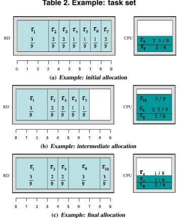
task τ1 τ2 τ3 τ4 τ5 τ6 τ7 τ8 τ9 τ10
ai 3 1 1 1 1 1 1 3 3 1
Ui 39 29 29 19 19 19 29 29 29.5 39
Table 2. Example: task set
RD CPU
(a)Example: initial allocation
RD CPU
(b)Example: intermediate allocation
RD CPU
(c)Example: final allocation
Figure 1. Example Relocation
arrive before relocation is finished. We plan to address this problem as part of our future work, modifying our scheme to allow tasks to be admitted even during a relocation phase. A final note regards the management of software-only tasks, i.e. tasks that can only be scheduled on the CPU. Such tasks can be trivially included in our framework by simply forcing them to be allocated inTS→S.
4.2
Example
In this section we provide a comprehensive example of the admission control and relocation procedure. We assume an RD areaA= 9, task area in{1,3}and an optimal alloca-tion algorithm. The task set is reported in Table 2. Task pa-rameters were chosen to keep the example simple and easily understandable; they should not be considered as real task cases.
The initial situation is depicted in Figure 1(a), where the width of each task on the RD represents the number of slots occupied by its hardware configuration. Tasksτ1throughτ7 are running on the RD while tasksτ8, τ9are running on the
CPU. Note that sinceτ8, τ9have the lowestUaii ratio among the running tasks and there is no free space on the RD the allocation is optimal. This situation changes when simul-taneouslyτ6andτ7terminate and a new taskτ10arrives in the system. SinceU8+U9+U10= 79.5 ≤1, the task can be safely admitted on the CPU, producing the allocation shown in Figure 1(b).
A new allocation is then computed for task set T =
{τ1, τ2, τ3, τ4, τ5, τ8, τ9, τ10}. It is easy to see that in the optimal solutionτ1, τ2, τ3, τ9, τ10 are allocated on the RD andτ4, τ5, τ8on the CPU. Therefore we can derive the fol-lowing sets:
TH→H ={τ1, τ2, τ3},TH→S ={τ4, τ5},TS→S ={τ8}, TS→H={τ9, τ10}
Note that sinceaTH→H +aTH→S = 7, we add two
place-holder tasksτ11, τ12with area1and utilization0toTH→S
(no placeholder is necessary forTS→H). We can then run the GROUP PARTITION algorithm producing the follow-ing swappfollow-ing groups:
S2
H→S ={τ11}, SH→S1 ={τ12, τ4, τ5}, SS→H2 ={τ10},
S1
S→H={τ9}
Once swapping groups have been defined, we check the fea-sibility conditions:
1. U8+U9+U10+U11=79.5 ≤1
2. U8+U9+U10+U11−U10+U12+U4+U5= 6.5 9 ≤1 3. U8+U4+U5+U9=69.5 ≤1
We can finally relocate tasks as described in Section 4 by first swapping S2
H→S withSS→H2 and then swapping
S1
H→S withSS→H1 . Since all feasibility conditions hold,
according to Theorem 5 no task misses its deadline. The final resulting allocation is shown in Figure 1(c).
5
Simulation Results
We have measured the effectiveness of our relocation strategy through a series of synthetic simulations. In par-ticular, we have compared our admission test against a ref-erence test which simply tries to allocate each new task on the RD firstly and on the CPU secondly, rejecting the task if there is not sufficient free area and free utilization. It is worth noticing that, to the best of our knowledge, no bet-ter test exists in the libet-terature to perform admission con-trol when using the described system; in fact, our compar-ison choice is a trivial extension of the reference algorithm shown in [23].
For each test, we have simulated the arrival of 100,000 synthetic tasks, and determined the rejection rate in term of the percentage of the area of rejected tasks with respect to all tasks arrived in the system. For each synthetic taskτi, the areaaiis randomly chosen to account for tasks with very different computational requirements and the utilizationUi
is randomly generated with mean proportional to ai. We define the loadLof the system in a given interval of time
[t1, t2]as the load offered by all tasks activated in[t1, t2]:
L([t1, t2]) =
∀τiactivated in [t1,t2]UiT
t2−t1
(13) whereT is the average time that a task remains in the sys-tem; therefore,UiT is the mean execution time required by all jobs ofτi.Tis computed and task terminations are ran-domly generated such that the average load is equal to a given valueL. Note that since the mean value ofUiis pro-portional toai, we could redefine the offered load in term of
ai
A instead ofUias in [24]. Furthermore, since the system is
comprised of both a RD and a CPU, a load ofL≤2should lead to no rejection (in practice, since task arrivals and ter-minations constitute a random process, rejections happen even forL≤2).
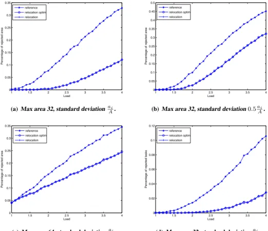
Figures 2(a),2(b),2(c),2(d) show a subset of the results for a RD area of 192 slots (Xilinx XC4VFX140), withL ranging from 1 to 4; a more comprehensive set of graphs can be found in [19]. In Figures 2(a) and 2(b) task area is chosen in set {1,2,4,8,16,32}, with smaller areas being extracted with higher probability than bigger ones (the av-erage task area is 3.05). In Figure 2(c) the area is chosen in set{1,2,4,8,16,32,64}, with each element being given equal probability (the average task area is 18.14). Task uti-lization is randomly generated with standard deviationai
A in
Figures 2(a) and 2(c) and0.5ai
A in Figure 2(b). Figure 2(d)
uses the same parameters as 2(a), but results are shown in term of the percentage of rejected tasks instead of rejected area. In all figures, relocation andrelocation optimrefer to our new admission test with relocation whilereference
is the reference test. The new allocation is computed us-ing the GREEDY algorithm inrelocation, while an optimal dynamic programming algorithm [13] is used inrelocation
optim. The average time needed to perform a single
admis-sion test is equal to 243µsforrelocationand 151 ms for
relocation optimon our test system (a Pentium IV at 2.8
Ghz). Note that graphs do not saturate since we plot them as a function of the load offered to the system and not of the load of accepted tasks.
Results in term of rejected tasks and rejected task area show similar trends; the percentage of rejected area is higher since tasks with bigger area are clearly more likely to be rejected. In all testsrelocationclearly outperforms refer-ence, rejecting less than one third of the tasks/area with re-spect toreferencein the most favorable case of Figure 2(a). The performance ofrelocationclearly depends on both the average task area and the utilization standard deviation,
withrelocationperforming better in the presence of small
tasks with big differences between area and utilization; note that since all systems proposed in Section 1 include differ-ent kinds of activities, we expect that some tasks, like sig-nal processing, can be much better optimized for hardware execution than others. The performance trend is expected, since the optimized allocation algorithm leads to better re-sults as the utilization standard deviation increases. In the same way, smaller tasks lead to smaller swapping groups
1 1.5 2 2.5 3 3.5 4 0 0.05 0.1 0.15 0.2 0.25 0.3 0.35 Load
Percentage of rejected area
reference relocation optim relocation
(a)Max area 32, standard deviationai
A. 1 1.5 2 2.5 3 3.5 4 0 0.05 0.1 0.15 0.2 0.25 0.3 0.35 0.4 0.45 0.5 Load
Percentage of rejected area
reference relocation optim relocation
(b)Max area 32, standard deviation0.5ai
A. 1 1.5 2 2.5 3 3.5 4 0 0.05 0.1 0.15 0.2 0.25 0.3 0.35 Load
Percentage of rejected area
reference relocation optim relocation
(c)Max area 64, standard deviationai
A. 1 1.5 2 2.5 3 3.5 4 0 0.02 0.04 0.06 0.08 0.1 0.12 Load
Percentage of rejected tasks
reference relocation optim relocation
(d)Max area 32, standard deviationai
A.
Figure 2. Experimental Results
with lower total utilization, therefore the reallocation phase is more likely to be feasibly executable.
Finally, note thatrelocation optimdoes not provide any performance improvement overrelocation, as predicted in Section 4.1. Since the run time overhead ofrelocation op-timis about three orders of magnitude greater with respect
torelocation, using the simpler GREEDY algorithm in the
allocation phase is the best choice.
6
Related Work
To the best of our knowledge, no previous work on com-bined scheduling of software/hardware tasks has been pub-lished. The closest related work is presented in [24, 23], dealing with the admission control problem for real-time hardware tasks, and in [7], dealing with scheduling algo-rithms for periodic hardware tasks. However, only hard aperiodic tasks are considered in [24, 23], and furthermore no mentioned work takes configuration overheads into ac-count.
The problem of on-line task allocation for non real-time hardware tasks, with the goal of minimizing task activation delay, has received more attention [2], including schemes that relocate (i.e. move) tasks on the RD mainly in the
inter-est of avoiding external fragmentation in the 1D and 2D area models [4, 5]. However, whenever relocation is performed tasks are assumed to be suspendable at any time, which can be difficult to achieve, and possibly for significant periods of time, which is unacceptable for real-time execution. In [8] a technique to relocate tasks on FPGAs without suspend-ing them is introduced, but there is no analysis of the over-head in term of area that needs to be left free on the RD to relocate a task.
7
Conclusions and Future Work
In this work, we have first proposed a pseudo-optimal allocation algorithm and a relocation scheme for relocatable tasks. We have then derived feasibility conditions for both software and hardware scheduling and we have defined an admission control test based on such conditions. Finally, the performance benefits of relocation have been measured through a series of synthetic simulations. Although we only considered systems comprised of a single CPU, we believe that our scheme can be easily adapted to multi-CPU systems by modifying the allocation algorithm.
As future work, we first plan to extend our analysis to the 1D and possibly 2D area models. Since such models are
affected by external fragmentation, a suitable defragmenta-tion scheme is needed to place tasks in a pseudo-optimal way. However, we believe that defragmentation can be eas-ily accounted for in the schedulability analysis.
Finally, as a long term objective we intend to develop an implementation of the proposed techniques on a working OSRD prototype.
References
[1] L. Abeni and G.Buttazzo. Integrating multimedia applica-tions in hard real-time systems. InProceedings of the 19th IEEE Real-Time Systems Symposium, Madrid, Spain, de-cember 1998.
[2] K. Bazargan, R. Kastner, and M. Sarrafzadeh. Fast template placement for reconfigurable computing systems.IEEE De-sign and Tests of Computers, 17(1):68–83, 2000.
[3] G. Berry, S. Moisan, and J.-P. Rigault. Esterel: Towards a synchronous and semantically sound high-level language for real-time applications. InProc. IEEE Real-Time Systems Symposium, pages 30–40, Arlington, Virginia, 1983. [4] G. Brebner and O. Diessel. Chip-based reconfigurable task
management. In Proceedings of the 11th International Conference on Field-Programmable Logic and Applications (FPL), pages 182–191, 2001.
[5] K. Compton, Z. Li, J. Cooley, S. Knol, and S. Hauck. Configuration relocation and defragmentation for run-time reconfigurable computing. IEEE Transactions on Very Large Scale Integration (VLSI) Systems, 10(3):209–220, June 2002.
[6] K. Danne and M. Platzner. Memory-demanding periodic real-time applications on FPGA computers. In Work-in-Progress of the 17th Euromicro Conference on Real-Time Systems (ECRTS), Palma de Mallorca, Spain, July 2005. [7] K. Danne and M. Platzner. Periodic real time scheduling for
FPGA computers. InThird IEEE Int’l Workshop on Intelli-gent Solutions in Embedded Systems (WISES), May 2005. [8] M. Gericota, G. Alves, M. Silva, and J. Ferreira.
On-line defragmentation for run-time partially reconfigurable FPGAs. InProceedings of the 12th International Confer-ence on Field-Programmable Logic and Applications (FPL), Montpellier, France, September 2002.
[9] J. M. Grasmeyer and M. T. Keennon. Development of the black widow micro air vehicle. InProceedings of AIAA Con-ference on Aerospace Sciences, 2001.
[10] G.Vanmeerbeeck, P.Schaumont, S.Vernalde, M.Engels, and I.Bolsens. Hardware/software partitioning for embedded systems in OCAPI-xl. InCODES’01, Copenhagen, Den-mark, April 2001.
[11] N. Halbwachs, P. Caspi, and D. Pilaud. The synchronous dataflow programming language Lustre. InAnother Look at Real Time Programming, Proceedings of the IEEE, Special Issue, September 1991.
[12] A. Howard, M. J. Matari´c, and G. S. Sukhatme. An in-cremental self-deployment algorithm for mobile sensor net-works.Autonomous Robots, 13(2):113–126, 2002.
[13] H. Kellerer, U. Pferschy, and D. Pisinger. Knapsack Prob-lems. Springer, 2004.
[14] C. Liu and J. Layland. Scheduling algorithms for multipro-gramming in a hard-real-time environment. Journal of the Association for Computing Machinery, 20(1), 1973. [15] T. Marescaux, A. Bartic, D. Verkest, S. Vernalde, and
R. Lauwereins. Interconnection networks enable fine-grain dynamic multi-tasking on FPGAs. InProc. of the 12th In-ternational Conference on Field-Programmable Logic and Applications (FPL), Montpellier, France, September 2002. [16] J.-Y. Mignolet, V. Nollet, P. Coene, D.Verkest, S. Vernalde,
and R. Lauwereins. Infrastructure for design and manage-ment of relocatable tasks in a heterogeneous reconfigurable system-on-chip. InProceedings of the DATE’03 conference, Munich, Germany, March 2003.
[17] J.-Y. Mignolet, S. Vernalde, D. Verkest, and R. Lauwere-ins. Enabling hardware-software multitasking on a recon-figurable computing platform for networked portable multi-media appliances. InProceedings of the International Con-ference on Engineering Reconfigurable Systems and Algo-rithms, pages 116–122, Las Vegas, June 2002.
[18] V. Nollet, P. Coene, D. Verkest, S. Vernalde, and R. Lauw-ereins. Designing an operating system for a heterogeneous reconfigurable SoC. InProceedings of the RAW’03 work-shop, Nice,France, April 2003.
[19] R. Pellizzoni and M. Caccamo. Adaptive real-time man-agement of relocatable tasks for FPGA-based embedded systems. Technical report, University of Illinois, 2005. http://pertsserver.cs.uiuc.edu/∼mcaccamo/papers/.
[20] C. Plessel, R. Enzler, H. Walder, J. Beutel, M. Platzner, L. Thiele, and G. Tr¨oster. The case for reconfigurable hard-ware in wearable computing.Personal and Ubiquitous Com-puting, October 2003.
[21] H. Simmler, L. Levinson, and R. M¨anner. Multitasking on FPGA coprocessors. InProc.10thInt’l Conf. Field Pro-grammable Logic and Applications, Villach, Austria, Au-gust 2000.
[22] G. Simon, M. Mar´oti, ´A. L´edeczi, G. Balogh, B. Kusy, A. N´adas, G. Pap, J. Sallai, and K. Frampton. Sensor network-based countersniper system. InProceedings of the ACM Second International Conference on Embedded Net-worked Sensor Systems (SenSys), 2004.
[23] C. Steiger, H. Walder, and M. Platzner. Operating systems for reconfigurable embedded platforms: Online schedul-ing of real-time tasks. IEEE Transactions on Computers, 53(11):1393–1407, 2004.
[24] C. Steiger, H. Walder, M. Platzner, and L. Thiele. Online scheduling and placement of real-time tasks to partially re-configurable devices. InProceedings of the24thIEEE Real-Time System Symposium, Cancun, Mexico, December 2003. [25] H. Walder and M. Platzner. Reconfigurable hardware op-erating systems: From concepts to realizations. InProc. Int’l Conf. Eng. of Reconfigurable Systems and Algorithms (ERSA), 2003.
[26] G. Wigley and D. Kearney. The development of an oper-ating system for reconfigurable computing. InProceedings IEEE Symposium FPGAs for Custom Computing Machines (FCCM), 2001.
[27] Xilinx, Inc.Virtex-4, Virtex-II Pro and Virtex-II Pro X FPGA User Guide. http://www.xilinx.com/.