City of Fontana ‐ Sierra Lakes Commerce Center Recirculated Draft EIR
Appendix
D:
Geotechnical
Investigation
GEOTECHNICAL INVESTIGATION
PROPOSED SIERRA AVENUE
DEVELOPMENT
SEC Sierra Avenue & Clubhouse Drive
Fontana, California
for
July 8, 2014
Trammell Crow Company 3501 Jamboree Road, Suite 230 Newport Beach, California 92660 Attention: Mr. Dave Drake
Senior Vice President Project No.: 14G151-1
Subject: Geotechnical Investigation
Proposed Sierra Avenue Development SEC Sierra Avenue and Clubhouse Drive Fontana, California
Gentlemen:
In accordance with your request, we have conducted a geotechnical investigation at the subject site. We are pleased to present this report summarizing the conclusions and recommendations developed from our investigation.
We sincerely appreciate the opportunity to be of service on this project. We look forward to providing additional consulting services during the course of the project. If we may be of further assistance in any manner, please contact our office.
Respectfully Submitted,
SOUTHERN CALIFORNIA GEOTECHNICAL, INC.
Daniel W. Nielsen, RCE 77915 Project Engineer
John A. Seminara, GE 2294 Principal Engineer
TABLE OF CONTENTS
1.0 EXECUTIVE SUMMARY
1
2.0 SCOPE OF SERVICES
3
3.0 SITE AND PROJECT DESCRIPTION
4
3.1 Site Conditions 4
3.2 Proposed Development 4
4.0 SUBSURFACE EXPLORATION
6
4.1 Scope of Exploration/Sampling Methods 6
4.2 Geotechnical Conditions 7
5.0 LABORATORY TESTING
8
6.0 CONCLUSIONS AND RECOMMENDATIONS
10
6.1 Seismic Design Considerations 10
6.2 Geotechnical Design Considerations 11
6.3 Site Grading Recommendations 13
6.4 Construction Considerations 16
6.5 Foundation Design and Construction 17
6.6 Floor Slab Design and Construction 18
6.7 Retaining Wall Design and Construction 19
6.9 Pavement Design Parameters 21
7.0 GENERAL COMMENTS
24
APPENDICES
A Plate 1: Site Location Map
Plate 2: Boring and Trench Location Plan B Boring and Trench Logs
C Laboratory Test Results D Grading Guide Specifications E Seismic Design Parameters
1.0 EXECUTIVE SUMMARY
Presented below is a brief summary of the conclusions and recommendations of this investigation. Since this summary is not all inclusive, it should be read in complete context with the entire report.
Site Preparation
Initial site preparation should include stripping of any surficial vegetation. The existing sparse to moderate vegetation including weeds, grasses and shrubs, and any organic soils should be properly disposed of off-site. Any trees which will not remain with the proposed development should also be removed, along with any associated root masses.
Initial site preparation should also include demolition of remnants of any previous development including the existing concrete slabs and pavements in the southwest portion of the site and the asphalt road which separates the northern parcel from the four southern parcels. Any foundations, utilities, septic systems, and any other improvements that will not remain in place with the new development should also be removed in their entirety. All debris resulting from demolition activities should be properly disposed of off-site. Concrete and asphalt debris may be re-used within the compacted fills, provided they are pulverized and the maximum particle size is less than 2 inches.
Undocumented fill soils were encountered at two of the borings and all of the trench locations, extending to depths of 1½ to 3± feet below current existing site grades.
The near surface fill and native alluvial soils within the upper 3± feet generally consist of loose to very dense and variable strength silty sands, sands, gravelly sands and sandy gravels with occasional cobble and boulder content. Results of laboratory testing indicate that some of the near surface soils possess minor to moderate potential for consolidation and collapse. The alluvium at depths greater than 3± feet generally possesses high strengths and densities and more favorable consolidation/collapse characteristics.
Based on these conditions, remedial grading is recommended within the proposed building areas in order to remove all of the artificial fill materials, any soils disturbed during demolition, and the upper portion of the near surface native alluvial soils. The existing soils within the proposed building area should be overexcavated to a depth of at least 3 feet below existing grade and to a depth of at least 3 feet below proposed pad grade. The proposed foundation influence zones should be overexcavated to a depth of 3 feet below proposed foundation bearing grade.
Following evaluation of the subgrade by the geotechnical engineer, the exposed subgrade soils should be scarified, moisture conditioned as necessary, and recompacted. The resulting soils may be replaced as structural fill, compacted to 90 percent of the ASTM D-1557 maximum dry density.
At depth greater than 2 to 3± feet, the on-site soils contain significant amounts of oversized materials, including cobbles and boulders. Where grading will require excavation into these materials, consideration should be given to using selective grading to remove the cobbles and/or boulders from these soils prior to reuse as fill. The placement of any oversized materials should be performed in accordance with the Grading Guide Specifications included in Appendix D of this report.
Building Foundations
Conventional shallow foundations, supported in newly placed compacted fill.
3,000 lbs/ft2maximum allowable soil bearing pressure.
Reinforcement consisting of at least two (2) No. 5 rebars (1 top and 1 bottom) in strip footings. Additional reinforcement may be necessary for structural considerations.
Building Floor Slabs
Conventional Slab-on-Grade, at least 5 inches thick.
Reinforcement is not required for geotechnical considerations. The actual floor slab reinforcement to be determined by the structural engineer, based on the proposed loading. Pavements ASPHALT PAVEMENTS (R = 60) Materials Thickness (inches) Parking Stalls (TI = 4.0) Auto Drive Lanes (TI = 5.0) Light Truck Traffic (TI = 6.0) Moderate Truck Traffic (TI = 7.0) Heavy Truck Traffic (TI = 8.0) Asphalt Concrete 3 3 3½ 4 5 Aggregate Base 3 3 3 3 3 Compacted Subgrade 12 12 12 12 12
PORTLAND CEMENT CONCRETE PAVEMENTS (R=60)
Materials Thickness (inches) Automobile Parking and Drive Areas Light Truck Traffic Areas (TI =6.0) Moderate Truck Traffic Areas (TI =7.0) Heavy Truck Traffic Areas (TI =8.0) PCC 5 5 6 7 Compacted Subgrade (95% minimum compaction) 12 12 12 12
2.0 SCOPE OF SERVICES
The scope of services performed for this project was in accordance with our Proposal No. 14P248, dated May 20, 2014. The scope of services included a visual site reconnaissance, subsurface exploration, field and laboratory testing, and geotechnical engineering analysis to provide criteria for preparing the design of the building foundations, building floor slabs, and parking lot pavements along with site preparation recommendations and construction considerations for the proposed development. The evaluation of the environmental aspects of this site was beyond the scope of services for this geotechnical investigation.
3.0 SITE AND PROJECT DESCRIPTION
3.1 Site Conditions
The subject site is located at the southeast corner of Sierra Avenue and Clubhouse Drive in Fontana, California. The site is bounded to the north and south by commercial/industrial buildings, to the east by a sand and gravel quarry, and to the west by Sierra Avenue. The general location of the site is illustrated on the Site Location Map included as Plate 1 in Appendix A of this report.
The site consists of five (5) contiguous parcels, totaling 27.45± acres in size. The largest of these parcels, located in the northern portion of the site, is separated from the four southern parcels by an asphaltic concrete road which traverses the site in an east-west direction. The asphaltic concrete paved road is in poor condition with extensive cracking and weathering. The northern parcel is currently vacant and undeveloped. Several dirt roads traverse the northern parcel in north-south and east-west directions. Ground surface cover within the northern parcel generally consists of exposed soil with slight to moderate native grass and weed growth and limited areas of open graded gravel. Cobbles and boulders were observed at the ground surface within the northern parcel.
The four southern parcels are generally vacant and undeveloped with the exception of the southwestern portion of the site which contains some remnants of previous development. Two Portland cement concrete slabs are located in the southwestern area of the site. The ground surface in the immediate vicinity on the east side of these concrete slabs consists of asphaltic concrete pavements. The concrete slabs and asphaltic concrete pavements are in poor condition with extensive cracking and fatigue throughout. The remaining areas of the southern four parcels are vacant and undeveloped. Ground surface cover within these parcels generally consists of exposed soil with sparse to moderate native weed and grass growth. Cobbles and boulders were observed at the ground surface throughout these parcels. Some trees are present near the property lines.
Topographic information for the subject site was obtained from a site plan provided by RGA. Based on this plan, the maximum site elevation of 1612.0± feet mean sea level (msl) is located in the northeast region of the site and the minimum site elevation of 1585.5± feet msl is located in the southeast region of the site. Generally, the site slopes downward to the south at a gradient of less than 3± percent. The overall topographic relief of the site is approximately 26.5 feet.
3.2 Proposed Development
Based on the architectural site plan prepared by RGA, the site will be developed with one (1) new commercial/industrial building, approximately 612,206 ft2 in size. The building will be
constructed in a cross-dock configuration with loading docks along the north and south sides of the building. The building will be surrounded by Portland cement concrete pavements in the truck loading dock areas and asphaltic concrete pavements in the automobile parking and drive lanes. Several landscape planter areas and concrete flatwork will be included throughout the site.
Detailed structural information has not been provided. It is assumed that the new building will be a single story structure of tilt-up concrete construction. Based on the assumed construction, maximum column and wall loads are expected to be on the order of 80 kips and 3 to 5 kips per linear foot, respectively.
Based on the site topography, cuts and fills of up to 7 to 8± feet are expected to be necessary to achieve the proposed site grades. No significant amounts of below grade construction, such as basements or crawl spaces, are expected to be included in the proposed development.
4.0 SUBSURFACE EXPLORATION
4.1 Scope of Exploration/Sampling Methods
The subsurface exploration conducted for this project consisted of seven (7) borings advanced to depths of 5 to 20± feet below current existing site grades. All of the borings were logged during drilling by a member of our staff.
In addition to the seven borings, a total of five (5) trenches were excavated within the proposed building area to depths of 5 to 9± feet below current existing site grades. These trenches were excavated using a backhoe with a 36-inch wide bucket. All of the trenches were logged during excavation by a member of our staff.
The borings were advanced with hollow-stem augers, by a truck-mounted drilling rig.. Relatively undisturbed samples were taken with a split barrel “California Sampler” containing a series of one inch long, 2.416± inch diameter brass rings. This sampling method is described in ASTM Test Method D-3550. In-situ samples were also taken using a 1.4± inch inside diameter split spoon sampler, in general accordance with ASTM D-1586. Both of these samplers are driven into the ground with successive blows of a 140-pound weight falling 30 inches. The blow counts obtained during driving are recorded for further analysis. Bulk samples were collected in plastic bags to retain their original moisture content. The relatively undisturbed ring samples were placed in molded plastic sleeves that were then sealed and transported to our laboratory.
Several of the borings were terminated at shallower depths than anticipated due to the presence of cobbles and/or boulders. Cobbles were observed in the auger spoils at various depths at all of the boring locations. It is not possible to determine the quantity and extent of the cobbles and boulders using conventional hollow-stem augers and conventional split-spoon samplers, since the diameters of the samplers are relatively small compared to cobble and boulder-sized particles. Therefore, the cobble and boulder content is expected to vary from the estimates shown on the Boring Logs. However, cobbles and boulders were observed during excavation and logging at all of the exploratory trenches. Based on our observations at the five exploratory trenches, and shallow refusal conditions at the boring locations, the subsurface profile possesses varying quantities of cobble and boulder content throughout, with zones of extensive cobbles and boulders.
The approximate locations of the borings and trenches are indicated on the Boring and Trench Location Plan, included as Plate 2 in Appendix A of this report. The Boring and Trench Logs, which illustrate the conditions encountered at the boring and trench locations, as well as the results of some of the laboratory testing, are included in Appendix B.
4.2 Geotechnical Conditions Pavements
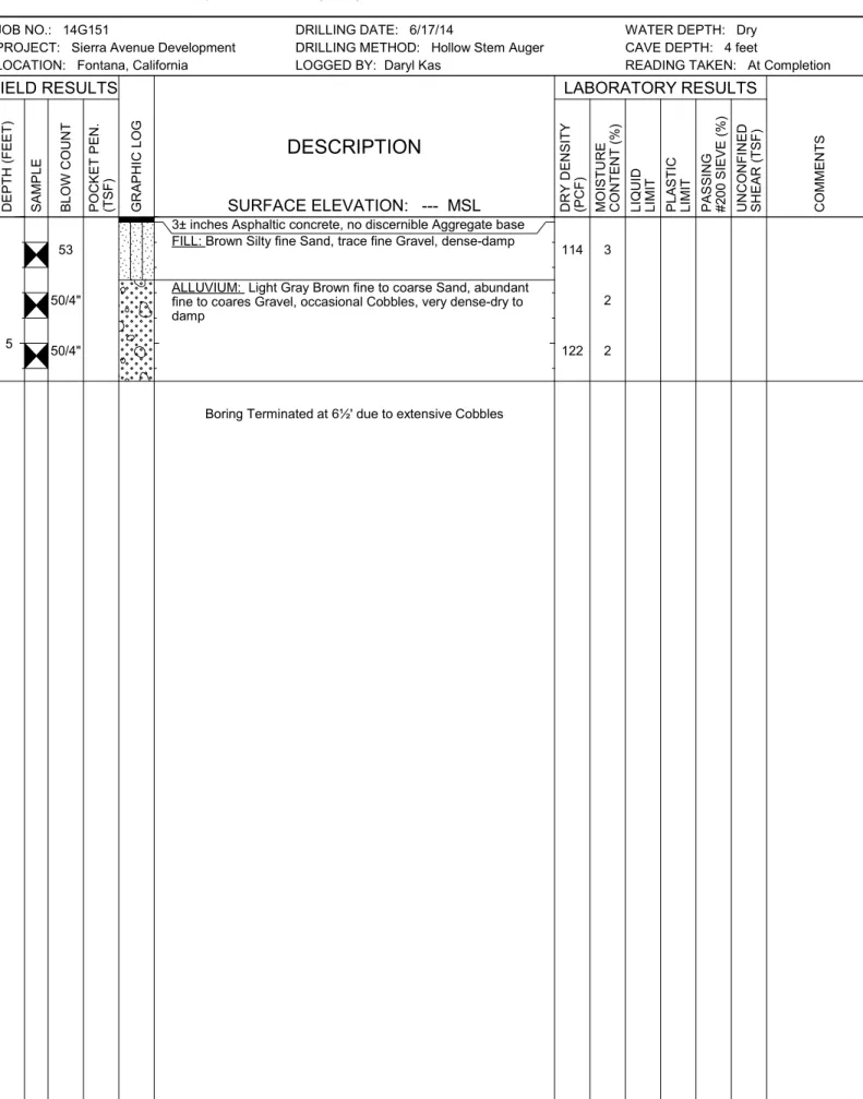
Boring No. B-1 encountered asphaltic concrete pavements at the ground surface. The pavement section consists of 3± inches of asphaltic concrete with no discernible underlying layer of aggregate base.
Artificial Fill
Artificial fill soils were encountered beneath the pavements at Boring No. B-1 and at the ground surface at Boring No. 5 and all five of the trench locations. The fill soils generally consist of loose to dense silty fine sands, fine sands, and silty fine to coarse sands with varying fine to coarse gravel content and occasional cobbles extending to depths of 1½ to 3± feet below existing site grades. The fill soils possess variable strengths and a disturbed appearance, resulting in their classification as fill.
Alluvium
Native alluvial soils were encountered at the ground surface at Boring Nos. B-2, B-3, and B-4 and beneath fill soils at the remaining borings and all of the trench locations. The alluvial soils generally consist of medium dense to very dense fine to coarse sands, gravelly fine to coarse sands, and fine to coarse sandy gravels with varying cobble and boulder content extending to the maximum depth explored of 20± feet.
Groundwater
Free water was not encountered during the drilling of any of the borings nor during the excavation of the exploratory trenches. Based on the lack of any water within the borings, and the moisture contents of the recovered soil samples, the static groundwater table is considered to have existed at a depth in excess of 20± feet at the time of the subsurface exploration.
5.0 LABORATORY TESTING
The soil samples recovered from the subsurface exploration were returned to our laboratory for further testing to determine selected physical and engineering properties of the soils. The tests are briefly discussed below. It should be noted that the test results are specific to the actual samples tested, and variations could be expected at other locations and depths.
Classification
All recovered soil samples were classified using the Unified Soil Classification System (USCS), in accordance with ASTM D-2488. The field identifications were then supplemented with additional visual classifications and/or by laboratory testing. The USCS classifications are shown on the Boring and Trench Logs and are periodically referenced throughout this report.
In-situ Density and Moisture Content
The density has been determined for selected relatively undisturbed ring samples. These densities were determined in general accordance with the method presented in ASTM D-2937. The results are recorded as dry unit weight in pounds per cubic foot. The moisture contents are determined in accordance with ASTM D-2216, and are expressed as a percentage of the dry weight. These test results are presented on the Boring and Trench Logs.
Consolidation
Selected soil samples were tested to determine their consolidation potential, in accordance with ASTM D-2435. The testing apparatus is designed to accept either natural or remolded samples in a one-inch high ring, approximately 2.416 inches in diameter. Each sample is then loaded incrementally in a geometric progression and the resulting deflection is recorded at selected time intervals. Porous stones are in contact with the top and bottom of the sample to permit the addition or release of pore water. The samples are typically inundated with water at an intermediate load to determine their potential for collapse or heave. The results of the consolidation testing are plotted on Plates C-1 through C-4 in Appendix C of this report.
Soluble Sulfates
Representative samples of the near-surface soils were submitted to a subcontracted analytical laboratory for determination of soluble sulfate content. Soluble sulfates are naturally present in soils, and if the concentration is high enough, can result in degradation of concrete which comes into contact with these soils. The results of the soluble sulfate testing are presented below, and are discussed further in a subsequent section of this report.
Sample Identification Soluble Sulfates (%) ACI Classification
B-1 @ 0 to 5 feet 0.003 Negligible
Maximum Dry Density and Optimum Moisture Content
A representative bulk sample was tested for its maximum dry density and optimum moisture content. The results have been obtained using the Modified Proctor procedure, per ASTM D-1557. These tests are generally used to compare the in-situ densities of undisturbed field samples, and for later compaction testing. Additional testing of other soil type or soil mixes may be necessary at a later date. The results of the testing are plotted on Plate C-5 in Appendix C of this report.
6.0 CONCLUSIONS AND RECOMMENDATIONS
Based on the results of our review, field exploration, laboratory testing and geotechnical analysis, the proposed development is considered feasible from a geotechnical standpoint. The recommendations contained in this report should be taken into the design, construction, and grading considerations. The recommendations are contingent upon all grading and foundation construction activities being monitored by the geotechnical engineer of record. The Grading Guide Specifications, included as Appendix D, should be considered part of this report, and should be incorporated into the project specifications. The contractor and/or owner of the development should bring to the attention of the geotechnical engineer any conditions that differ from those stated in this report, or which may be detrimental for the development.
6.1 Seismic Design Considerations
The subject site is located in an area which is subject to strong ground motions due to earthquakes. The performance of a site specific seismic hazards analysis was beyond the scope of this investigation. However, numerous faults capable of producing significant ground motions are located near the subject site. Due to economic considerations, it is not generally considered reasonable to design a structure that is not susceptible to earthquake damage. Therefore, significant damage to structures may be unavoidable during large earthquakes. The proposed structures should, however, be designed to resist structural collapse and thereby provide reasonable protection from serious injury, catastrophic property damage and loss of life.
Faulting and Seismicity
Research of available maps indicates that the subject site is not located within an Alquist-Priolo Earthquake Fault Zone. Therefore, the possibility of significant fault rupture on the site is considered to be low.
Seismic Design Parameters
Based on standards in place at the time of this report, the proposed development must be designed in accordance with the requirements of the 2013 California Building Code (CBC). The CBC provides procedures for earthquake resistant structural design that include considerations for on-site soil conditions, occupancy, and the configuration of the structure including the structural system and height. The seismic design parameters presented below are based on the soil profile and the proximity of known faults with respect to the subject site.
The 2013 CBC Seismic Design Parameters have been generated using U.S. Seismic Design Maps, a web-based software application developed by the United States Geological Survey. This software application, available at the USGS web site, calculates seismic design parameters in accordance with the 2013 CBC, utilizing a database of deterministic site accelerations at 0.01 degree intervals. The table below is a compilation of the data provided by the USGS application. A copy of the output generated from this program is included in Appendix E of this report. A
copy of the Design Response Spectrum, as generated by the USGS application is also included in Appendix E. Based on this output, the following parameters may be utilized for the subject site:
2013 CBC SEISMIC DESIGN PARAMETERS
Parameter Value
Mapped Spectral Acceleration at 0.2 sec Period SS 1.897
Mapped Spectral Acceleration at 1.0 sec Period S1 0.800
Site Class --- D
Site Modified Spectral Acceleration at 0.2 sec Period SMS 1.897
Site Modified Spectral Acceleration at 1.0 sec Period SM1 1.199
Design Spectral Acceleration at 0.2 sec Period SDS 1.265
Design Spectral Acceleration at 1.0 sec Period SD1 0.800
Liquefaction
Liquefaction is the loss of the strength in generally cohesionless, saturated soils when the pore-water pressure induced in the soil by a seismic event becomes equal to or exceeds the overburden pressure. The primary factors which influence the potential for liquefaction include groundwater table elevation, soil type and grain size characteristics, relative density of the soil, initial confining pressure, and intensity and duration of ground shaking. The depth within which the occurrence of liquefaction may impact surface improvements is generally identified as the upper 50 feet below the existing ground surface. Liquefaction potential is greater in saturated, loose, poorly graded fine sands with a mean (d50) grain size in the range of 0.075 to 0.2 mm (Seed and Idriss, 1971). Clayey (cohesive) soils or soils which possess clay particles (d<0.005mm) in excess of 20 percent (Seed and Idriss, 1982) are generally not considered to be susceptible to liquefaction, nor are those soils which are above the historic static groundwater table.
The California Geological Survey (CGS) has not yet conducted seismic hazard mapping in the area of the subject site. The San Bernardino County Land Use Plan, Geologic Hazard Overlays, Devore Quadrangle, FH21C, indicates that the subject site is not located within a zone of liquefaction susceptibility. In addition, the subsurface conditions at the boring locations are not considered to be conducive to liquefaction. Based on the mapping performed by San Bernardino County and the conditions encountered at the boring locations, liquefaction is not considered to be a design concern for this project.
6.2 Geotechnical Design Considerations General
The near-surface fill and native alluvial soils within the upper the upper 3± feet vary in density and composition. The fill soils generally consist of loose to very dense silty fine sands, silty fine
to coarse sands, and fine to coarse sands with varying gravel content and occasional cobbles. The near-surface alluvium consists of medium dense to very dense fine to coarse sands, gravelly sands, and sandy gravels, with some cobble content and occasional boulders. Results of consolidation/collapse testing indicate that the native alluvium encountered at depths of 1 to 2± feet possesses a moderate potential for collapse. Based on their variable strengths, in their present condition, the near-surface fill and alluvium are not considered suitable to support the foundation loads of the new building, and could result in excessive post-construction settlements. Furthermore, no documentation of the placement or compaction of the existing fill soils has been provided. Therefore, the fill soils encountered within the upper 1½ to 3± feet are considered to be undocumented fill, unsuitable for the support of any building foundations. The native alluvial soils at greater depths generally consist of high strength fine to coarse sands, gravelly sands and sandy gravels. Laboratory testing indicates that the soils encountered at depth of 3± feet and greater possess favorable consolidation/collapse characteristics.
Based on these conditions, remedial grading is considered warranted within the proposed building area in order to remove all of the undocumented fill soils, any soils disturbed during demolition of the existing structures, and the upper portion of the near surface, native alluvial soils.
Settlement
The proposed remedial grading will remove the existing undocumented fill soils and the potentially collapsible/variable density alluvium from within the proposed building area. The native soils that will remain in place below the recommended depth of overexcavation will not be subject to significant load increases from the foundations of the new structure. Therefore, following completion of the recommended remedial grading, post-construction settlements are expected to be within tolerable limits.
Expansion
The near surface soils generally consist of gravelly sands, sandy gravels and fine to coarse sands with varying amounts of silt, gravel, cobble, and boulder content. These materials have been visually classified as very low to non-expansive. Therefore, no design considerations related to expansive soils are considered warranted for this site.
Soluble Sulfates
The results of the soluble sulfate testing indicate that the selected samples of the on-site soils contain negligible concentrations of soluble sulfates, in accordance with American Concrete Institute (ACI) guidelines. Therefore, specialized concrete mix designs are not considered to be necessary, with regard to sulfate protection purposes. It is, however, recommended that additional soluble sulfate testing be conducted at the completion of rough grading to verify the soluble sulfate concentrations of the soils which are present at pad grade within the building area.
Shrinkage/Subsidence
Based on the results of the laboratory testing, removal and recompaction of the near surface fill soils and native alluvium is estimated to result in an average shrinkage of 8 to 12 percent. Minor ground subsidence is expected to occur in the soils below the zone of removal, due to settlement and machinery working. The subsidence is estimated to be 0.1± feet.
These estimates are based on previous experience with nearby projects and the subsurface conditions encountered at the boring locations. The actual amount of subsidence is expected to be variable and will be dependent on the type of machinery used, repetitions of use, and dynamic effects, all of which are difficult to assess precisely.
Foundation Plan Review
Foundation plans were not available at the time of this report. It is therefore recommended that we be provided with copies of the preliminary foundation plans, when they become available, for review with regard to the conclusions, recommendations, and assumptions contained within this report.
6.3 Site Grading Recommendations
The grading recommendations presented below are based on the subsurface conditions encountered at the boring and trench locations and our understanding of the proposed development. We recommend that all grading activities be completed in accordance with the Grading Guide Specifications included as Appendix D of this report, unless superseded by site-specific recommendations presented below.
Site Stripping and Demolition
Initial site preparation should include the demolition of the of any remnants of previous development, including the existing concrete slabs, asphaltic concrete pavements, and any foundations, utilities, septic systems and any other improvements that will not remain in place with the new development. Concrete and asphalt debris may be re-used within the compacted fills, provided they are pulverized and the maximum particle size is less than 2 inches.
Additionally, initial site stripping should include removal of any surficial vegetation. This should include weeds, grasses, shrubs, and any trees that will not remain with the proposed development. The actual extent of site stripping should be determined in the field by the geotechnical engineer, based on the organic content and stability of the materials encountered. Treatment of Existing Soils: Building Pad
Overexcavation should be performed within the proposed building area to remove all of the existing undocumented fill soils, any soils disturbed during demolition, and a portion of the near surface native alluvium. The fill soils extend to depths of 1½ to 3± feet at the boring and trench locations, where encountered. The building pad overexcavation should also extend to a depth of at least 3 feet below existing grade and to a depth of at least 3 feet below proposed
pad grade throughout the building areas. Within the foundation influence zones, the overexcavation should extend to depths of at least 3 feet below proposed foundation bearing grade.
The overexcavation areas should extend at least 5 feet beyond the building perimeters and foundations, and to an extent equal to the depth of fill below the new foundations. If the proposed structure incorporate any exterior columns (such as for a canopy or overhang) the overexcavations should also encompass these areas.
Following completion of the overexcavation, the subgrade soils within the building area should be evaluated by the geotechnical engineer to verify their suitability to serve as the structural fill subgrade, as well as to support the foundation loads of the new structures. This evaluation should include proofrolling with a heavy rubber-tired vehicle to identify any soft, loose or otherwise unstable soils that must be removed. Some localized areas of deeper excavation may be required if dry, loose, porous, low density or otherwise unsuitable materials are encountered at the base of the overexcavation.
After a suitable overexcavation subgrade has been achieved, the exposed soils should be scarified to a depth of at least 12 inches, and thoroughly flooded to raise the moisture content of the underlying soils to at least 2 to 4 percent above optimum moisture content, extending to a depth of at least 24 inches. The exposed overexcavation subgrades should be recompacted using heavy vibratory compaction equipment prior to placement of any fill. The previously excavated soils may then be replaced as compacted structural fill.
Treatment of Existing Soils: Retaining Walls and Site Walls
The existing soils within the areas of any proposed retaining walls should be overexcavated to a depth of 2 feet below foundation bearing grade and replaced as compacted structural fill as discussed above for the proposed building pad. The foundation areas for non-retaining site walls should be overexcavated to a depth of 1 feet below proposed foundation bearing grade. Any undocumented fill soils within any of these foundation areas should be removed in their entirety. The overexcavation subgrade soils should be evaluated by the geotechnical engineer prior to scarifying, moisture conditioning, and recompacting the upper 12 inches of exposed subgrade soils, as discussed for the building areas. The previously excavated soils may then be replaced as compacted structural fill.
Treatment of Existing Soils: Parking Areas
Based on economical considerations, removal and replacement of the existing potentially collapsible alluvium and undocumented fill is not considered warranted within the proposed parking areas. Subgrade preparation in the new parking and drive areas should initially consist of removal of all soils disturbed during stripping and demolition operations. The geotechnical engineer should then evaluate the subgrade to identify any areas of additional unsuitable soils. Based on the presence of undocumented fill soils throughout the site, it is expected that some isolated areas of additional overexcavation may be required to remove zones of lower strength, unsuitable soils. The subgrade soils should then be scarified to a depth of 12± inches, moisture
conditioned to 2 to 4 percent above optimum moisture content (to a depth of at least 24 inches) and recompacted to at least 90 percent of the ASTM D-1557 maximum dry density. The grading recommendations presented above for the proposed parking and drive areas assume that the owner and/or developer can tolerate minor amounts of settlement within the proposed parking areas. The grading recommendations presented above do not completely mitigate the extent of collapsible native soils and undocumented fill in the parking areas. As such, settlement and associated pavement distress could occur. Typically, repair of such distressed areas involves significantly lower costs than completely mitigating these soils at the time of construction.
Fill Placement
Fill soils should be placed in thin (6 inches), near-horizontal lifts, moisture conditioned to 2 to 4 percent above the optimum moisture content, and compacted.
On-site soils may be used for fill provided they are cleaned of any debris to the satisfaction of the geotechnical engineer. The on-site soils, especially below depths of 2 to 3± feet, possess significant quantities of oversized material, including cobbles and boulders. Some sorting and/or crushing of these materials may be required to generate soils that are suitable for reuse as compacted structural fill.
All grading and fill placement activities should be completed in accordance with the requirements of the CBC and the grading code of the city of Fontana.
All fill soils should be compacted to at least 90 percent of the ASTM D-1557 maximum dry density. Fill soils should be well mixed.
Compaction tests should be performed periodically by the geotechnical engineer as random verification of compaction and moisture content. These tests are intended to aid the contractor. Since the tests are taken at discrete locations and depths, they may not be indicative of the entire fill and therefore should not relieve the contractor of his responsibility to meet the job specifications.
Selective Grading and Oversized Material Placement
The native alluvial soils below depths of 2 to 5± feet possess significant cobble and/or boulder content. Based on conditions encountered at the trench locations, the soils at depths of 2 to 3 feet and greater possess appreciable cobbles and/or boulder content. It is expected that large scrapers (Caterpillar 657 or equivalent) will be adequate to move the cobble containing soils as well as some of the soils containing smaller boulders. However, some larger boulders (2 to 3± feet in size) were also encountered at the trench locations. It may be necessary to move these larger particles individually, and place them as oversized materials in accordance with the Grading Guide Specifications, in Appendix D of this report.
Since the proposed grading will require excavation of cobble and boulder containing soils, it may be desirable to selectively grade the proposed building pad area. The presence of particles greater than 3 inches in diameter within the upper 1 to 3 feet of the building pad subgrade will impact the utility and foundation excavations. Depending on the depths of fills required within the proposed parking areas, it may be feasible to sort the on-site soils, placing the materials greater than 3 inches in diameter within the lower depths of the fills, and limiting the upper 1 to
3 feet of soils to materials less than 3 inches in size. Oversized materials could also be placed within the lower depths of the recommended overexcavations. In order to achieve this grading, it would likely be necessary to use rock buckets and/or rock sieves to separate the oversized materials from the remaining soil. Although such selective grading will facilitate further construction activities, it is not considered mandatory and a suitable subgrade could be achieved without such extensive sorting. However, in any case, it is recommended that all materials greater than 6 inches in size be excluded from the upper 1 foot of the surface of any compacted fills.
The placement of any oversized materials should be performed in accordance with the Grading Guide Specifications included in Appendix D of this report. If disposal of oversized materials is required, rock blankets or windrows should be used and such areas should be observed during construction and placement by a representative of the geotechnical engineer.
Imported Structural Fill
All imported structural fill should consist of very low expansive (EI < 20), well graded soils possessing at least 10 percent fines (that portion of the sample passing the No. 200 sieve). As discussed previously, imported fill for use below new flatwork should consist of very low expansive (EI < 20) material. Additional specifications for structural fill are presented in the Grading Guide Specifications, included as Appendix D.
Utility Trench Backfill
In general, all utility trench backfill should be compacted to at least 90 percent of the ASTM D-1557 maximum dry density. As an alternative, a clean sand (minimum Sand Equivalent of 30) may be placed within trenches and compacted in place (jetting or flooding is not recommended). Compacted trench backfill should conform to the requirements of the local grading code, and more restrictive requirements may be indicated by the city of Fontana. All utility trench backfills should be witnessed by the geotechnical engineer. The trench backfill soils should be compaction tested where possible; probed and visually evaluated elsewhere. Utility trenches which parallel a footing, and extending below a 1h:1v plane projected from the outside edge of the footing should be backfilled with structural fill soils, compacted to at least 90 percent of the ASTM D-1557 standard. Pea gravel backfill should not be used for these trenches.
6.4 Construction Considerations Excavation Considerations
The near surface soils generally consist of gravelly sands, sandy gravels and fine to coarse sands with varying amounts of silt, gravel, cobble, and boulder content. Based on their composition, caving of shallow excavations may occur. Where caving occurs within shallow excavations, flattened excavation slopes may be sufficient to provide excavation stability. On a preliminary basis, temporary excavations should be laid back at a slope no steeper than 2h:1v.
Deeper excavations may require some form of external stabilization such as shoring or bracing. Maintaining adequate moisture content within the near surface soils will improve excavation stability. All excavation activities on this site should be conducted in accordance with Cal-OSHA regulations.
Groundwater
The static groundwater table at this site is considered to exist at a depth in excess of 20 feet. Therefore, groundwater is not expected to impact the grading or foundation construction activities.
6.5 Foundation Design and Construction
Based on the preceding grading recommendations, the new building pad will be underlain by structural fill soils used to replace existing undocumented fill and variable strength, collapsible native soils. The new structural fill soils are expected to extend to a depth of at least 3 feet below foundation bearing grade underlain by existing native soils that have been densified in place. Based on this subsurface profile, the proposed structure may be supported on shallow foundations.
Foundation Design Parameters
New square and rectangular footings may be designed as follows:
Maximum, net allowable soil bearing pressure: 3,000 lbs/ft2.
Minimum wall/column footing width: 14 inches/24 inches.
Minimum longitudinal steel reinforcement within strip footings: Two (2) No. 5 rebars (1 top and 1 bottom).
Minimum foundation embedment: 12 inches into suitable structural fill soils, and at least 18 inches below adjacent exterior grade. Interior column footings may be placed immediately beneath the floor slab.
It is recommended that the perimeter building foundations be continuous across all exterior doorways. Any flatwork adjacent to the exterior doors should be doweled into the perimeter foundations in a manner determined by the structural engineer.
The allowable bearing pressures presented above may be increased by 1/3 when considering short duration wind or seismic loads. The minimum steel reinforcement recommended above is based on standard geotechnical practice. The actual design of the foundations should be determined by the structural engineer.
Foundation Construction
The foundation subgrade soils should be evaluated at the time of overexcavation, as discussed in Section 6.3 of this report. It is further recommended that the foundation subgrade soils be evaluated by the geotechnical engineer immediately prior to steel or concrete placement. Soils suitable for direct foundation support should consist of newly placed structural fill, compacted to at least 90 percent of the ASTM D-1557 maximum dry density. Any unsuitable materials should be removed to a depth of suitable bearing compacted structural fill, with the resulting excavations backfilled with compacted fill soils. As an alternative, lean concrete slurry (500 to 1,500 psi) may be used to backfill such isolated overexcavations.
The foundation subgrade soils should also be properly moisture conditioned to 2 to 4 percent above the Modified Proctor optimum, to a depth of at least 12 inches below bearing grade. Since it is typically not feasible to increase the moisture content of the floor slab and foundation subgrade soils once rough grading has been completed, care should be taken to maintain the moisture content of the building pad subgrade soils throughout the construction process.
Estimated Foundation Settlements
Post-construction total and differential settlements of shallow foundations designed and constructed in accordance with the previously presented recommendations are estimated to be less than 1.0 and 0.5 inches, respectively, under static conditions. Differential movements are expected to occur over a 30-foot span, thereby resulting in an angular distortion of less than 0.002 inches per inch.
Lateral Load Resistance
Lateral load resistance will be developed by a combination of friction acting at the base of foundations and slabs and the passive earth pressure developed by footings below grade. The following friction and passive pressure may be used to resist lateral forces:
Passive Earth Pressure: 300 lbs/ft3
Friction Coefficient: 0.30
These are allowable values, and include a factor of safety. When combining friction and passive resistance, the passive pressure component should be reduced by one-third. These values assume that footings will be poured directly against compacted structural fill. The maximum allowable passive pressure is 2500 lbs/ft2.
6.6 Floor Slab Design and Construction
Subgrades which will support new floor slabs should be prepared in accordance with the recommendations contained in the Site Grading Recommendations section of this report. Based on the anticipated grading which will occur at this site, the floors of the proposed structures may be constructed as conventional slabs on grade supported on newly placed
structural fill, extending to a depth of at least 3 feet below finished pad grade. Based on geotechnical considerations, the floor slabs may be designed as follows:
Minimum slab thickness: 5 inches.
Minimum slab reinforcement: Not required for geotechnical considerations. The actual floor slab reinforcement should be determined by the structural engineer, based on the imposed loading.
If moisture sensitive floor coverings will be used then minimum slab underlayment should consist of a moisture vapor barrier constructed below the entire area of the proposed slab where such floor coverings will be used. The moisture vapor barrier should meet or exceed the Class A rating as defined by ASTM E 1745-97 and have a permeance rating less than 0.01 perms as described in ASTM E 96-95 and ASTM E 154-88. The moisture vapor barrier should be properly constructed in accordance with all applicable manufacturer specifications. Given that a rock free subgrade is anticipated and that a capillary break is not required, sand below the barrier is not required. The need for sand and/or the amount of sand above the moisture vapor barrier should be specified by the structural engineer or concrete contractor. The selection of sand above the barrier is not a geotechnical engineering issue and hence outside our purview.
Moisture condition the floor slab subgrade soils to 2 to 4 percent above the Modified Proctor optimum moisture content, to a depth of 12 inches. The moisture content of the floor slab subgrade soils should be verified by the geotechnical engineer within 24 hours prior to concrete placement.
Proper concrete curing techniques should be utilized to reduce the potential for slab curling or the formation of excessive shrinkage cracks.
The actual design of the floor slab should be completed by the structural engineer to verify adequate thickness and reinforcement.
6.7 Retaining Wall Design and Construction
Although not indicated on the conceptual grading plan, some small (less than 3 to 5± feet in height) retaining walls may be required to facilitate the new site grades. It is also expected that some retaining walls will be required in the new loading dock areas. The parameters recommended for use in the design of these walls are presented below.
Retaining Wall Design Parameters
Based on the soil conditions encountered at the boring locations, the following parameters may be used in the design of new retaining walls for this site. We have provided parameters assuming the use of on-site soils for retaining wall backfill. The on-site soils generally consist of gravelly sands, sandy gravels and fine to coarse sands with varying amounts of silt, gravel, cobble, and boulder content. When compacted to at least 90 percent of the ASTM D-1557
maximum dry density, these soils are expected to possess a friction angle of at least 32 degrees.
If desired, SCG could provide design parameters for an alternative select backfill material behind the retaining walls. The use of select backfill material could result in lower lateral earth pressures. In order to use the design parameters for the imported select fill, this material must be placed within the entire active failure wedge. This wedge is defined as extending from the heel of the retaining wall upwards at an angle of approximately 60° from horizontal. If select backfill material behind the retaining wall is desired, SCG should be contacted for supplementary recommendations.
RETAINING WALL DESIGN PARAMETERS
Design Parameter
Soil Type
On-Site Silty Sands and Sands
Internal Friction Angle () 32
Unit Weight 130 lbs/ft3 Equivalent Fluid Pressure: Active Condition (level backfill) 40 lbs/ft3 Active Condition (2h:1v backfill) 61 lbs/ft3 At-Rest Condition (level backfill) 61 lbs/ft3
Regardless of the backfill type, the walls should be designed using a soil-footing coefficient of friction of 0.30 and an equivalent passive pressure of 300 lbs/ft3. The structural engineer should incorporate appropriate factors of safety in the design of the retaining walls.
The active earth pressure may be used for the design of retaining walls that do not directly support structures or support soils that in turn support structures and which will be allowed to deflect. The at-rest earth pressure should be used for walls that will not be allowed to deflect such as those which will support foundation bearing soils, or which will support foundation loads directly.
Where the soils on the toe side of the retaining wall are not covered by a "hard" surface such as a structure or pavement, the upper 1 foot of soil should be neglected when calculating passive resistance due to the potential for the material to become disturbed or degraded during the life of the structure.
Seismic Lateral Earth Pressures
In accordance with the 2013 CBC, any retaining walls more than 6 feet in height must be designed for seismic lateral earth pressures. If walls 6 feet or more are required for this site, the geotechnical engineer should be contacted for supplementary seismic lateral earth pressure recommendations.
Retaining Wall Foundation Design
The foundation subgrade soils for the new retaining should be prepared in accordance with the grading recommendations presented in Section 6.3 of this report.
Backfill Material
On-site soils may be used to backfill the retaining walls. However, all backfill material placed within 3 feet of the back wall face should have a particle size no greater than 3 inches. The retaining wall backfill materials should be well graded.
It is recommended that a properly installed prefabricated drainage composite such as the MiraDRAIN 6000XL (or approved equivalent), which is specifically designed for use behind retaining walls, be placed against the face of the retaining walls. This drainage composite should extend from the top of the retaining wall footing to within 1 foot of the ground surface on the back side of the retaining wall. If the backfill soils are not covered by an impermeable surface, such as a structure or pavement, a 12-inch thick layer of a low permeability soil should be placed over the backfill to reduce surface water migration to the underlying soils.
All retaining wall backfill should be placed and compacted under engineering controlled conditions in the necessary layer thicknesses to ensure an in-place density between 90 and 93 percent of the maximum dry density as determined by the Modified Proctor test (ASTM D1557). Care should be taken to avoid over-compaction of the soils behind the retaining walls, and the use of heavy compaction equipment should be avoided.
Subsurface Drainage
As previously indicated, the retaining wall design parameters are based upon drained backfill conditions. Consequently, some form of permanent drainage system will be necessary in conjunction with the appropriate backfill material. Subsurface drainage may consist of either:
A weep hole drainage system typically consisting of a series of 4-inch diameter holes in the wall situated slightly above the ground surface elevation on the exposed side of the wall and at an approximate 8-foot on-center spacing. The weep holes should include a 2 cubic foot pocket of open graded gravel, surrounded by an approved geotextile fabric, at each weep hole location.
A 4-inch diameter perforated pipe surrounded by 2 cubic feet of gravel per linear foot of drain placed behind the wall, above the retaining wall footing. The gravel layer should be wrapped in a suitable geotextile fabric to reduce the potential for migration of fines. The footing drain should be extended to daylight or tied into a storm drainage system. 6.9 Pavement Design Parameters
Site preparation in the pavement area should be completed as previously recommended in the
Site Grading Recommendations section of this report. The subsequent pavement recommendations assume proper drainage and construction monitoring, and are based on
either PCA or CALTRANS design parameters for a twenty (20) year design period. However, these designs also assume a routine pavement maintenance program to obtain the anticipated 20-year pavement service life.
Pavement Subgrades
It is anticipated that the new pavements will be primarily supported on recompacted native alluvial soils that consist of sands, silty sands and sandy gravels. Based on their composition, the on-site soils are expected to possess R-values of greater than 60. Therefore, the pavement sections for the on-site asphalt and concrete pavements should be designed using a conservative R-Value of 60. Any fill material imported to the site should have support characteristics equal to or greater than that of the on-site soils and be placed and compacted under engineering controlled conditions. It may be desirable to perform R-value testing after the completion of rough grading to verify the R-value of the as-graded subgrade.
Asphaltic Concrete
Presented below are the recommended thicknesses for new flexible pavement structures consisting of asphaltic concrete over a granular base. An alternate pavement section has been provided for use in parking stall areas due to the anticipated lower traffic intensity in these areas. However, truck traffic must be excluded from areas where the thinner pavement section is used; otherwise premature pavement distress may occur. The pavement designs are based on the traffic indices (TI’s) indicated. The client and/or civil engineer should verify that these TI’s are representative of the anticipated traffic volumes.
Traffic Index No. of Heavy Trucks per Day
4.0 0
5.0 1
6.0 3
7.0 11
8.0 35
For the purpose of the traffic volumes indicated above, a truck is defined as a 5-axle tractor trailer unit with one 8-kip axle and two 32-kip tandem axles. All of the traffic indices allow for 1,000 automobiles per day.
ASPHALT PAVEMENTS (R = 60) Materials Thickness (inches) Parking Stalls (TI = 4.0) Auto Drive Lanes (TI = 5.0) Light Truck Traffic (TI = 6.0) Moderate Truck Traffic (TI = 7.0) Heavy Truck Traffic (TI = 8.0) Asphalt Concrete 3 3 3½ 4 5 Aggregate Base 3 3 3 3 3 Compacted Subgrade 12 12 12 12 12
The aggregate base course should be compacted to at least 95 percent of the ASTM D-1557 maximum dry density. The asphaltic concrete should be compacted to at least 95 percent of the Marshall maximum density, as determined by ASTM D-2726. The aggregate base course may consist of crushed aggregate base (CAB) or crushed miscellaneous base (CMB), which is a recycled gravel, asphalt and concrete material. The gradation, R-Value, Sand Equivalent, and Percentage Wear of the CAB or CMB should comply with appropriate specifications contained in the current edition of the “Greenbook” Standard Specifications for Public Works Construction. Portland Cement Concrete
The preparation of the subgrade soils within Portland cement concrete pavement areas should be performed as previously described for proposed asphalt pavement areas. The minimum recommended thicknesses for the Portland Cement Concrete pavement sections are as follows:
PORTLAND CEMENT CONCRETE PAVEMENTS (R = 60)
Materials Thickness (inches) Automobile Parking and Drive Areas Light Truck Traffic Areas (TI =6.0) Moderate Truck Traffic Areas (TI =7.0) Heavy Truck Traffic Areas (TI =8.0) PCC 5 5 6 7 Compacted Subgrade (95% minimum compaction) 12 12 12 12
The concrete should have a 28-day compressive strength of at least 3,000 psi. Reinforcing within all pavements should be designed by the structural engineer. The maximum joint spacing within all of the PCC pavements is recommended to be equal to or less than 30 times the pavement thickness. The actual joint spacing and reinforcing of the Portland cement concrete pavements should be determined by the structural engineer.
7.0 GENERAL COMMENTS
This report has been prepared as an instrument of service for use by the client, in order to aid in the evaluation of this property and to assist the architects and engineers in the design and preparation of the project plans and specifications. This report may be provided to the contractor(s) and other design consultants to disclose information relative to the project. However, this report is not intended to be utilized as a specification in and of itself, without appropriate interpretation by the project architect, civil engineer, and/or structural engineer. The reproduction and distribution of this report must be authorized by the client and Southern California Geotechnical, Inc. Furthermore, any reliance on this report by an unauthorized third party is at such party’s sole risk, and we accept no responsibility for damage or loss which may occur. The client(s)’ reliance upon this report is subject to the Engineering Services Agreement, incorporated into our proposal for this project.
The analysis of this site was based on a subsurface profile interpolated from limited discrete soil samples. While the materials encountered in the project area are considered to be representative of the total area, some variations should be expected between boring locations and sample depths. If the conditions encountered during construction vary significantly from those detailed herein, we should be contacted immediately to determine if the conditions alter the recommendations contained herein.
This report has been based on assumed or provided characteristics of the proposed development. It is recommended that the owner, client, architect, structural engineer, and civil engineer carefully review these assumptions to ensure that they are consistent with the characteristics of the proposed development. If discrepancies exist, they should be brought to our attention to verify that they do not affect the conclusions and recommendations contained herein. We also recommend that the project plans and specifications be submitted to our office for review to verify that our recommendations have been correctly interpreted.
The analysis, conclusions, and recommendations contained within this report have been promulgated in accordance with generally accepted professional geotechnical engineering practice. No other warranty is implied or expressed.
SITE
PROPOSED SIERRA AVENUE DEVELOPMENT SCALE: 1" = 2400'
SITE LOCATION MAP FONTANA, CALIFORNIA SOURCE: SAN BERNARDINO COUNTY
B-1 B-7 B-2 T-1 B-4 B-3 B-6 B-5 T-5 T-4 T-3 T-2 SCALE: 1" = 120' DRAWN: BI FONTANA, CALIFORNIA
PROPOSED SIERRA AVENUE DEVELOPMENT BORING AND TRENCH LOCATION PLAN
GEOTECHNICAL LEGEND
SoCalGeo
APPROXIMATE BORING LOCATION
APPROXIMATE TRENCH LOCATION
BORING LOG LEGEND
SAMPLE TYPE
GRAPHICAL SYMBOLSAMPLE DESCRIPTION
AUGER
SAMPLE COLLECTED FROM AUGER CUTTINGS, NO FIELD MEASUREMENT OF SOIL STRENGTH. (DISTURBED)CORE
ROCK CORE SAMPLE: TYPICALLY TAKEN WITH A DIAMOND-TIPPED CORE BARREL. TYPICALLY USED ONLY IN HIGHLY CONSOLIDATED BEDROCK.GRAB
1
SOIL SAMPLE TAKEN WITH NO SPECIALIZED EQUIPMENT, SUCH AS FROM A STOCKPILE OR THE GROUND SURFACE. (DISTURBED)CS
CALIFORNIA SAMPLER: 2-1/2 INCH I.D. SPLIT BARREL SAMPLER, LINED WITH 1-INCH HIGH BRASS RINGS. DRIVEN WITH SPT HAMMER. (RELATIVELYUNDISTURBED)
NSR
NO RECOVERY: THE SAMPLING ATTEMPT DID NOT RESULT IN RECOVERY OF ANY SIGNIFICANT SOIL OR ROCK MATERIAL.SPT
STANDARD PENETRATION TEST: SAMPLER IS A 1.4 INCH INSIDE DIAMETER SPLIT BARREL, DRIVEN 18 INCHES WITH THE SPT HAMMER. (DISTURBED)SH
SHELBY TUBE: TAKEN WITH A THIN WALL SAMPLE TUBE, PUSHED INTO THE SOIL AND THEN EXTRACTED. (UNDISTURBED)VANE
VANE SHEAR TEST: SOIL STRENGTH OBTAINED USING A 4 BLADED SHEAR DEVICE. TYPICALLY USED IN SOFT CLAYS-NO SAMPLE RECOVERED.COLUMN DESCRIPTIONS
DEPTH: Distance in feet below the ground surface.
SAMPLE: Sample Type as depicted above.
BLOW COUNT: Number of blows required to advance the sampler 12 inches using a 140 lb hammer with a 30-inch drop. 50/3” indicates penetration refusal (>50 blows) at 3 inches. WH indicates that the weight of the hammer was sufficient to push the sampler 6 inches or more.
POCKET PEN.: Approximate shear strength of a cohesive soil sample as measured by pocket penetrometer.
GRAPHIC LOG: Graphic Soil Symbol as depicted on the following page.
DRY DENSITY: Dry density of an undisturbed or relatively undisturbed sample in lbs/ft3.
MOISTURE CONTENT: Moisture content of a soil sample, expressed as a percentage of the dry weight.
LIQUID LIMIT: The moisture content above which a soil behaves as a liquid.
PLASTIC LIMIT: The moisture content above which a soil behaves as a plastic.
PASSING #200 SIEVE: The percentage of the sample finer than the #200 standard sieve.
SM
SP
COARSE GRAINED SOILSSW
TYPICAL
DESCRIPTIONS
WELLGRADED GRAVELS, GRAVEL -SAND MIXTURES, LITTLE OR NO FINES
SILTY GRAVELS, GRAVEL SAND -SILT MIXTURES
LETTER
GRAPH
POORLY-GRADED GRAVELS, GRAVEL - SAND MIXTURES, LITTLE OR NO FINES
GC
GM
GP
GW
POORLY-GRADED SANDS, GRAVELLY SAND, LITTLE OR NO FINES SILTS AND CLAYS MORE THAN 50% OF MATERIAL IS LARGER THAN NO. 200 SIEVE SIZE MORE THAN 50% OF MATERIAL IS SMALLER THAN NO. 200 SIEVE SIZE MORE THAN 50% OF COARSE FRACTION PASSING ON NO. 4 SIEVE MORE THAN 50% OF COARSE FRACTION RETAINED ON NO.4 SIEVE CLAYEY GRAVELS, GRAVEL SAND
-CLAY MIXTURES FINE GRAINED SOILS
SYMBOLS
MAJOR DIVISIONS
SOIL CLASSIFICATION CHART
OH
CH
MH
OL
CL
ML
CLEAN SANDSSC
SILTY SANDS, SAND - SILT MIXTURES
CLAYEY SANDS, SAND - CLAY MIXTURES
INORGANIC SILTS AND VERY FINE SANDS, ROCK FLOUR, SILTY OR CLAYEY FINE SANDS OR CLAYEY SILTS WITH SLIGHT PLASTICITY INORGANIC CLAYS OF LOW TO MEDIUM PLASTICITY, GRAVELLY CLAYS, SANDY CLAYS, SILTY CLAYS, LEAN CLAYS
ORGANIC SILTS AND ORGANIC SILTY CLAYS OF LOW PLASTICITY
INORGANIC SILTS, MICACEOUS OR DIATOMACEOUS FINE SAND OR SILTY SOILS
INORGANIC CLAYS OF HIGH PLASTICITY
ORGANIC CLAYS OF MEDIUM TO HIGH PLASTICITY, ORGANIC SILTS
PEAT, HUMUS, SWAMP SOILS WITH
SILTS AND CLAYS GRAVELS WITH FINES SAND AND SANDY
SOILS (LITTLE OR NO FINES)
SANDS WITH FINES LIQUID LIMIT LESS THAN 50 LIQUID LIMIT GREATER THAN 50 GRAVEL AND GRAVELLY SOILS (APPRECIABLE AMOUNT OF FINES) (APPRECIABLE AMOUNT OF FINES) (LITTLE OR NO FINES)
WELL-GRADED SANDS, GRAVELLY SANDS, LITTLE OR NO FINES
CLEAN GRAVELS
53
50/4"
50/4"
3± inches Asphaltic concrete, no discernible Aggregate base FILL: Brown Silty fine Sand, trace fine Gravel, dense-damp
ALLUVIUM: Light Gray Brown fine to coarse Sand, abundant fine to coares Gravel, occasional Cobbles, very dense-dry to damp
Boring Terminated at 6½' due to extensive Cobbles
114 122 3 2 2 JOB NO.: 14G151
PROJECT: Sierra Avenue Development LOCATION: Fontana, California
BORING NO.
B-1
DRILLING DATE: 6/17/14
DRILLING METHOD: Hollow Stem Auger LOGGED BY: Daryl Kas
FIELD RESULTS LABORATORY RESULTS
COMMEN
TS
SURFACE ELEVATION: --- MSL
WATER DEPTH: Dry CAVE DEPTH: 4 feet
READING TAKEN: At Completion
5 GRAP HI C LOG PAS SI NG #2 00 SI EVE (%)
DESCRIPTION
POCK ET P EN . (TSF) UN CON FIN ED SH EAR (TSF) DR Y D EN SITY (PCF) DE PTH (FEET) MOISTU RE CON TEN T (%)LIQUID LIMIT PLASTI
C LIMIT SAMP LE BLOW C OUN T 51.GPJ SOC ALGE O.GDT 7 /8/14
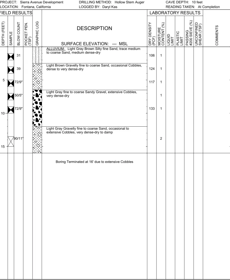
31 39 72/9" 50/5" 72/9" 90/11"
ALLUVIUM: Light Gray Brown Silty fine Sand, trace medium to coarse Sand, medium dense-dry
Light Brown Gravelly fine to coarse Sand, occasional Cobbles, dense to very dense-dry
Light Gray fine to coarse Sandy Gravel, extensive Cobbles, very dense-dry
Light Gray Gravelly fine to coarse Sand, occasional to extensive Cobbles, very dense-dry to damp
Boring Terminated at 16' due to extensive Cobbles
106 124 117 133 1 1 1 1 1 2 JOB NO.: 14G151
PROJECT: Sierra Avenue Development LOCATION: Fontana, California
BORING NO.
B-2
DRILLING DATE: 6/17/14
DRILLING METHOD: Hollow Stem Auger LOGGED BY: Daryl Kas
FIELD RESULTS LABORATORY RESULTS
COMMEN
TS
SURFACE ELEVATION: --- MSL
WATER DEPTH: Dry CAVE DEPTH: 10 feet
READING TAKEN: At Completion
5 10 15 GRAP HI C LOG PAS SI NG #2 00 SI EVE (%)
DESCRIPTION
POCK ET P EN . (TSF) UN CON FIN ED SH EAR (TSF) DR Y D EN SITY (PCF) DE PTH (FEET) MOISTU RE CON TEN T (%)LIQUID LIMIT PLASTI
C LIMIT SAMP LE BLOW C OUN T 51.GPJ SOC ALGE O.GDT 7 /8/14
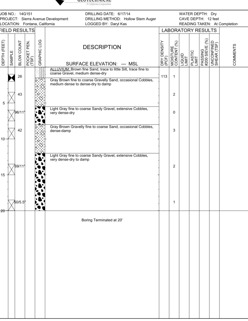
26 43 96/11" 42 69/11" 50/5.5"
ALLUVIUM: Brown fine Sand, trace to little Silt, trace fine to coarse Gravel, medium dense-dry
Gray Brown fine to coarse Gravelly Sand, occasional Cobbles, medium dense to dense-dry to damp
Light Gray fine to coarse Sandy Gravel, extensive Cobbles, very dense-dry
Gray Brown Gravelly fine to coarse Sand, occasional Cobbles, dense-damp
Light Gray fine to coarse Sandy Gravel, extensive Cobbles, very dense-dry to damp
Boring Terminated at 20' 113 1 2 0 3 2 1 JOB NO.: 14G151
PROJECT: Sierra Avenue Development LOCATION: Fontana, California
BORING NO.
B-3
DRILLING DATE: 6/17/14
DRILLING METHOD: Hollow Stem Auger LOGGED BY: Daryl Kas
FIELD RESULTS LABORATORY RESULTS
COMMEN
TS
SURFACE ELEVATION: --- MSL
WATER DEPTH: Dry CAVE DEPTH: 12 feet
READING TAKEN: At Completion
5 10 15 20 GRAP HI C LOG PAS SI NG #2 00 SI EVE (%)
DESCRIPTION
POCK ET P EN . (TSF) UN CON FIN ED SH EAR (TSF) DR Y D EN SITY (PCF) DE PTH (FEET) MOISTU RE CON TEN T (%)LIQUID LIMIT PLASTI
C LIMIT SAMP LE BLOW C OUN T 51.GPJ SOC ALGE O.GDT 7 /8/14
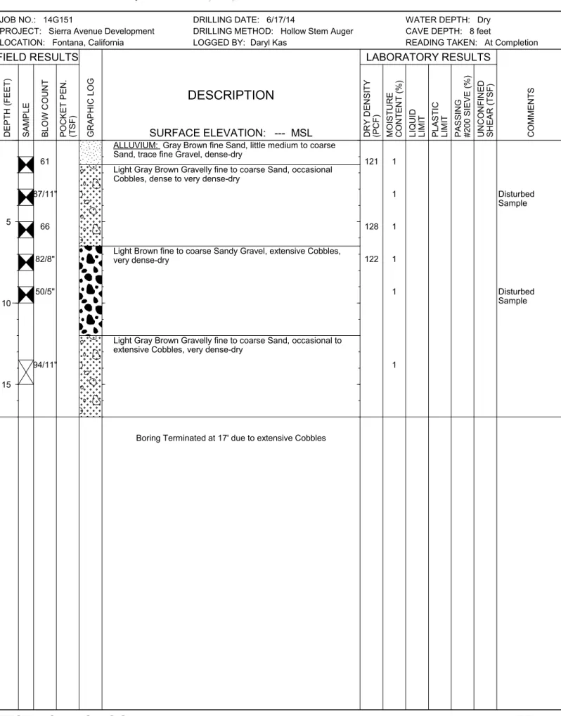
61 87/11" 66 82/8" 50/5" 94/11"
ALLUVIUM: Gray Brown fine Sand, little medium to coarse Sand, trace fine Gravel, dense-dry
Light Gray Brown Gravelly fine to coarse Sand, occasional Cobbles, dense to very dense-dry
Light Brown fine to coarse Sandy Gravel, extensive Cobbles, very dense-dry
Light Gray Brown Gravelly fine to coarse Sand, occasional to extensive Cobbles, very dense-dry
Boring Terminated at 17' due to extensive Cobbles
Disturbed Sample Disturbed Sample 121 128 122 1 1 1 1 1 1 JOB NO.: 14G151
PROJECT: Sierra Avenue Development LOCATION: Fontana, California
BORING NO.
B-4
DRILLING DATE: 6/17/14
DRILLING METHOD: Hollow Stem Auger LOGGED BY: Daryl Kas
FIELD RESULTS LABORATORY RESULTS
COMMEN
TS
SURFACE ELEVATION: --- MSL
WATER DEPTH: Dry CAVE DEPTH: 8 feet
READING TAKEN: At Completion
5 10 15 GRAP HI C LOG PAS SI NG #2 00 SI EVE (%)
DESCRIPTION
POCK ET P EN . (TSF) UN CON FIN ED SH EAR (TSF) DR Y D EN SITY (PCF) DE PTH (FEET) MOISTU RE CON TEN T (%)LIQUID LIMIT PLASTI
C LIMIT SAMP LE BLOW C OUN T 51.GPJ SOC ALGE O.GDT 7 /8/14
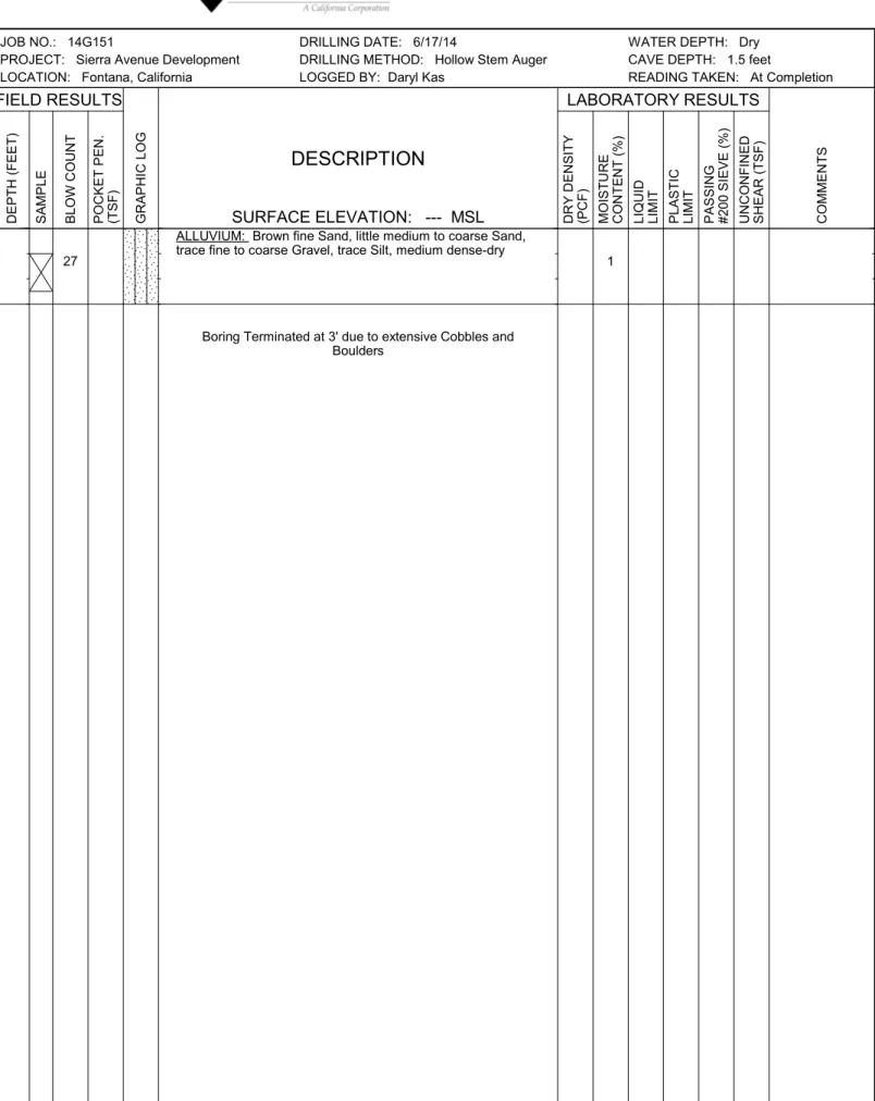
27
ALLUVIUM: Brown fine Sand, little medium to coarse Sand, trace fine to coarse Gravel, trace Silt, medium dense-dry
Boring Terminated at 3' due to extensive Cobbles and Boulders
1 JOB NO.: 14G151
PROJECT: Sierra Avenue Development LOCATION: Fontana, California
BORING NO.
B-5
DRILLING DATE: 6/17/14
DRILLING METHOD: Hollow Stem Auger LOGGED BY: Daryl Kas
FIELD RESULTS LABORATORY RESULTS
COMMEN
TS
SURFACE ELEVATION: --- MSL
WATER DEPTH: Dry CAVE DEPTH: 1.5 feet
READING TAKEN: At Completion
GRAP HI C LOG PAS SI NG #2 00 SI EVE (%)
DESCRIPTION
POCK ET P EN . (TSF) UN CON FIN ED SH EAR (TSF) DR Y D EN SITY (PCF) DE PTH (FEET) MOISTU RE CON TEN T (%)LIQUID LIMIT PLASTI
C LIMIT SAMP LE BLOW C OUN T 51.GPJ SOC ALGE O.GDT 7 /8/14
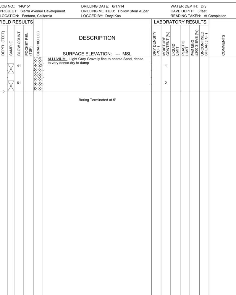
41
61
ALLUVIUM: Light Gray Gravelly fine to coarse Sand, dense to very dense-dry to damp
Boring Terminated at 5'
1
2 JOB NO.: 14G151
PROJECT: Sierra Avenue Development LOCATION: Fontana, California
BORING NO.
B-6
DRILLING DATE: 6/17/14
DRILLING METHOD: Hollow Stem Auger LOGGED BY: Daryl Kas
FIELD RESULTS LABORATORY RESULTS
COMMEN
TS
SURFACE ELEVATION: --- MSL
WATER DEPTH: Dry CAVE DEPTH: 3 feet
READING TAKEN: At Completion
5 GRAP HI C LOG PAS SI NG #2 00 SI EVE (%)
DESCRIPTION
POCK ET P EN . (TSF) UN CON FIN ED SH EAR (TSF) DR Y D EN SITY (PCF) DE PTH (FEET) MOISTU RE CON TEN T (%)LIQUID LIMIT PLASTI
C LIMIT SAMP LE BLOW C OUN T 51.GPJ SOC ALGE O.GDT 7 /8/14
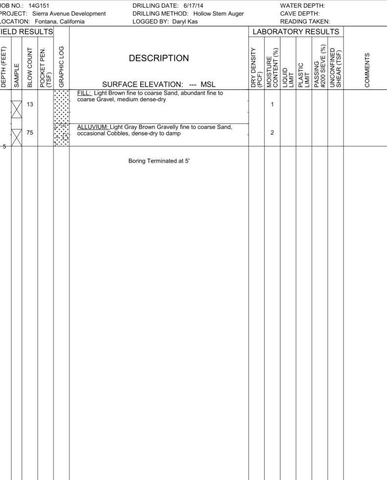
13
75
FILL: Light Brown fine to coarse Sand, abundant fine to coarse Gravel, medium dense-dry
ALLUVIUM: Light Gray Brown Gravelly fine to coarse Sand, occasional Cobbles, dense-dry to damp
Boring Terminated at 5'
1
2 JOB NO.: 14G151
PROJECT: Sierra Avenue Development LOCATION: Fontana, California
BORING NO.
B-7
DRILLING DATE: 6/17/14
DRILLING METHOD: Hollow Stem Auger LOGGED BY: Daryl Kas
FIELD RESULTS LABORATORY RESULTS
COMMEN TS SURFACE ELEVATION: --- MSL WATER DEPTH: CAVE DEPTH: READING TAKEN: 5 GRAP HI C LOG PAS SI NG #2 00 SI EVE (%)
DESCRIPTION
POCK ET P EN . (TSF) UN CON FIN ED SH EAR (TSF) DR Y D EN SITY (PCF) DE PTH (FEET) MOISTU RE CON TEN T (%)LIQUID LIMIT PLASTI
C LIMIT SAMP LE BLOW C OUN T 51.GPJ SOC ALGE O.GDT 7 /8/14
TRENCH NO.
T-1
DEPTH SAMPLE DRY DENSITY (PCF) MOISTURE (%)EARTH MATERIALS
DESCRIPTION
GRAPHIC REPRESENTATION
5
10
15
JOB NO.: 14G151-1
PROJECT: Proposed Sierra Avenue Development LOCATION: Fontana, CA
DATE: 06-17-2014
SCALE: 1" = 5'
A: FILL: Light Gray Brown fine Sand, little medium to coarse Sand, trace Silt, loose-dry
B: ALLUVIUM: Light Brown fine to coarse Sandy Gravel, extensive Cobbles, occasional Boulders, medium dense-dry
C: ALLUVIUM: Light Brown fine to coarse Gravelly fine to coarse Sand, extensive Cobbles, occasional boulder, medium dense to dense-dry
WATER DEPTH: Dry
SEEPAGE DEPTH: Dry
READINGS TAKEN: At Completion EQUIPMENT USED: Backhoe
LOGGED BY: Daryl Kas ORIENTATION: S 5 E ELEVATION: 1608.5 feet msl S 5 E b Trench Terminated @ 8.5'
A
B
C
1 b 1 b 1 b 2 Boulder BoulderTRENCH NO.
T-2
DEPTH SAMPLE DRY DENSITY (PCF) MOISTURE (%)EARTH MATERIALS
DESCRIPTION
GRAPHIC REPRESENTATION
5
10
15
SCALE: 1" = 5' WATER DEPTH: Dry
SEEPAGE DEPTH: Dry
READINGS TAKEN: At Completion
N 90 E
Trench Terminated @ 9'
A: FILL: Light Gray Brown fine to medium Sand, little course Sand, trace Silt, trace fine to coarse Gravel, loose-dry
B: ALLUVIUM: Light Brown Gravelly fine to coarse Sand, medium dense-damp
C: ALLUVIUM: Light Gray Brown fine to coarse Sandy Gravel, extensive Cobbles, occasional Boulders, medium dense to dense-dry to damp D: ALLUVIUM: Light Brown fine to coarse Sandy Gravel, occasional to extensive Cobbles, dense-dry to damp
A
B
3
2 JOB NO.: 14G151-1
PROJECT: Proposed Sierra Avenue Development LOCATION: Fontana, CA
DATE: 06-17-2014
EQUIPMENT USED: Backhoe LOGGED BY: Daryl Kas ORIENTATION: N 90 E ELEVATION: 1599 feet msl
C
D
2 2 b b b bTRENCH NO.
T-3
DEPTH SAMPLE DRY DENSITY (PCF) MOISTURE (%)EARTH MATERIALS
DESCRIPTION
GRAPHIC REPRESENTATION
5
10
15
SCALE