User Guide for the Corroded
Asset Failure – Ferrous map
Open Report OR/14/001
OPEN REPORT OR/14/001
The National Grid and other Ordnance Survey data © Crown Copyright and database rights 2012. Ordnance Survey Licence No. 100021290.”
Keywords
Underground ferrous assets, ground stability, corrosion. Bibliographical reference Dearden, R.A., Tye, A.Mand Marchant, A.2013. User Guide for the Corroded Asset Failure – Ferrous map. British Geological Survey Open Report, OR/14/001. 24pp.
Copyright in materials derived from the British Geological Survey’s work is owned by the Natural Environment Research Council (NERC) and/or the authority that commissioned the work. You may not copy or adapt this publication without first obtaining permission. Contact the BGS Intellectual Property Rights Section, British Geological Survey, Keyworth,
e-mail [email protected]. You may quote extracts of a reasonable length without prior permission, provided a full acknowledgement is given of the source of the extract.
Maps and diagrams in this book use topography based on Ordnance Survey mapping.
User Guide for the Corroded
Asset Failure – Ferrous map
R Dearden, A Tye, A Marchant
The full range of our publications is available from BGS shops at Nottingham, Edinburgh, London and Cardiff (Welsh publications only) see contact details below or shop online at www.geologyshop.com
The London Information Office also maintains a reference collection of BGS publications, including maps, for consultation. We publish an annual catalogue of our maps and other publications; this catalogue is available online or from any of the BGS shops.
The British Geological Survey carries out the geological survey of Great Britain and Northern Ireland (the latter as an agency service for the government of Northern Ireland), and of the surrounding continental shelf, as well as basic research projects. It also undertakes programmes of technical aid in geology in developing countries.
The British Geological Survey is a component body of the Natural Environment Research Council.
British Geological Survey offices
BGS Central Enquiries Desk
Tel 0115 936 3143 Fax 0115 936 3276 email [email protected]
Environmental Science Centre, Keyworth, Nottingham NG12 5GG
Tel 0115 936 3241 Fax 0115 936 3488 email [email protected]
Murchison House, West Mains Road, Edinburgh EH9 3LA
Tel 0131 667 1000 Fax 0131 668 2683 email [email protected]
Natural History Museum, Cromwell Road, London SW7 5BD
Tel 020 7589 4090 Fax 020 7584 8270 Tel 020 7942 5344/45 email [email protected]
Columbus House, Greenmeadow Springs, Tongwynlais, Cardiff CF15 7NE
Tel 029 2052 1962 Fax 029 2052 1963
Maclean Building, Crowmarsh Gifford, Wallingford OX10 8BB
Tel 01491 838800 Fax 01491 692345
Geological Survey of Northern Ireland, Colby House, Stranmillis Court, Belfast BT9 5BF
Tel 028 9038 8462 Fax 028 9038 8461 www.bgs.ac.uk/gsni/
Parent Body
Natural Environment Research Council, Polaris House, North Star Avenue, Swindon SN2 1EU
Tel 01793 411500 Fax 01793 411501 www.nerc.ac.uk
Website www.bgs.ac.uk
i
Contents
Contents ... i
Summary ... iii
Acknowledgements ... iv
1
Introduction ... 5
2
About the Corroded Asset Failure - Ferrous map ... 6
2.1
Background ... 6
2.2
Who might require this map? ... 6
2.3
About the dataset ... 6
3
Using the dataset ... 8
3.1
GIS set-up ... 8
3.2
Explanation of sub-layers ... 9
4
What information does the dataset provide? ... 11
4.1
Overview ... 11
4.2
Data summary ... 13
5
Technical Information ... 13
5.1
Pre-requisite requirements ... 13
5.2
Creation of the dataset ... 13
5.3
Scale... 14
5.4
Dataset History ... 14
5.5
Coverage ... 14
5.6
Data Format ... 14
5.7
Limitations ... 15
6
Licensing Information ... 15
Appendix 1 ... 17
FIGURES
Figure 1 An example of the GIS layer that considers the potential for corroded assets to fail as a
result of ground instability ... 7
Figure 2 An example of the summary GIS layer that considers the potential for corroded assets to
fail as a result of ground instability ... 7
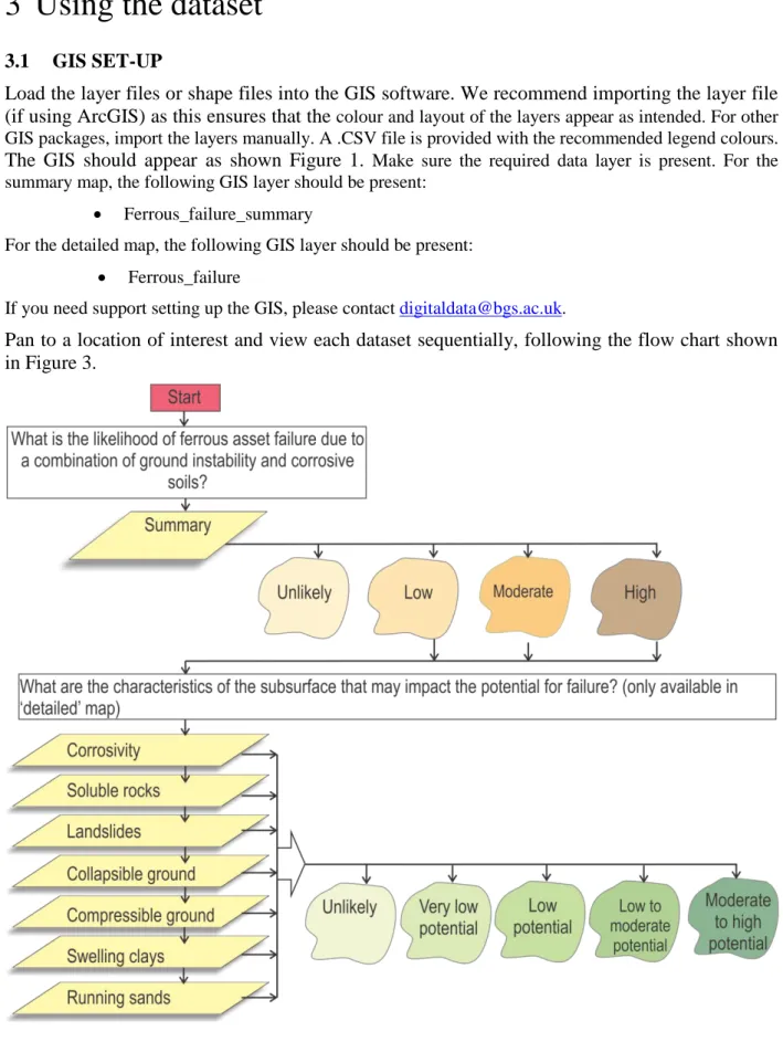
Figure 3 How to use the ‘ferrous_failure’ GIS layer. ... 8
TABLES
Table 1 Summary sub-layer – Description of attributes ... 9
Table 2 Corrosivity (Corrosiv) sub-layer – Description of attributes ... 9
Table 3 Compressibility (Compress) sub-layer – Description of attributes ... 9
Table 4 Shrink-swell (Swell) sub-layer – Description of attributes ... 10
Table 5 Collapsible deposits (Collapse) sub-layer – Description of attributes ... 10
Table 6 Running sands (Runsand) sub-layer – Description of attributes ... 10
Table 7 Landslides (lndslide) sub-layer – Description of attributes ... 10
Table 8 Dissolution (soluble) sub-layer – Description of attributes ... 11
Table 9. Details of the original datasets used in the
Corroded Asset Failure - Ferrous
map ... 13
iii
Summary
Ferrous (iron) structures and pipelines are susceptible to surface pitting and corrosion, which
weaken assets and increase the potential for failure. Such assets are more prone to failure where
ground movement occurs due to the change in stress around the asset. This user guide describes
the
Corroded Asset Failure - Ferrous
map, which has been developed by the BGS to help
identify where the condition of underground iron assets such as pipes, cables and building
foundations may be compromised. The dataset indicates where corroded assets may exist, and
where ground stability may result in asset failure.
This data is intended for asset managers who are responsible for assessing the condition of
underground iron assets. In particular, the data may be useful for water companies who need to
determine where leaks may occur in the pipe network. The data may be used to prioritise
maintenance to help meet leakage reduction targets in a cost effective manner. In addition, the
data may be useful at the desk study stage for selecting pipeline routes or to identify appropriate
construction materials.
Acknowledgements
We would like to thank David Entwisle for his help and advice in the creation of this product and
Jane Smalley for providing useful comments on this report. We’d also like to thank D
ŵ
r Cymru
and Yorkshire Water for feedback on the product and its potential applications.
5
1
Introduction
Founded in 1835, the British Geological Survey (BGS) is the world's oldest national geological
survey and the United Kingdom's premier centre for earth science information and expertise. The
BGS provides expert services and impartial advice in all areas of geosciences and has a client
base that is drawn from the public and private sectors both in the UK and internationally.
Our innovative digital data products aim to help describe the ground surface and subsurface
across the whole of Great Britain. These digital products are based on the outputs of the BGS
survey and research programmes and our substantial national data holdings. This data coupled
with our in-house geoscientific knowledge are combined to provide products relevant to a wide
range of users in central and local government, insurance and housing, engineering and
environmental business, and the British public.
Further information on all the digital data provided by the BGS can be found on our website at
http://www.bgs.ac.uk/data/home.html or by contacting:
Central Enquiries
British Geological Survey
Environmental Science Centre
Keyworth
Nottingham
NG12 5GG
Direct tel. +44(0)115 936 3143
Fax. +44(0)115 9363150
[email protected]
2
About the Corroded Asset Failure - Ferrous
map
2.1
BACKGROUND
Underground ferrous assets are structures in the ground that contain iron, such as foundations, cabling and gas, water and oil pipelines. The failure of underground assets is a significant problem for both historical and newly placed underground infrastructure. The term ‘failure’ covers assets which will no longer work according to their original specification; failure of a pipe may mean it leaks, or failure of a foundation may mean that its bearing capacity is compromised. Failure may occur as a result of the following factors (Makar, 2000):
• Corrosion
• External loading (differential ground movement)
• Manufacturing flaws
• Internal pressure
This dataset focuses on the susceptibility of assets to fail as a result of corrosion resulting from aggressive soils and differential ground movement. The effect of soil corrosivity on ferrous assets is dependent on the soil type and specifically the concentration of soluble salts such as sulphate and chloride, pH, soil resistivity, water content, temperature and soil redox potential. Ferrous assets that are corroded by aggressive soils have a reduced material thickness, which increases the chance of failure. This is particularly the case where differential ground movement occurs, putting greater external pressure on assets (Eidinger, 1998). Ground movement can occur in a variety of scenarios due to the susceptibility of geological deposits to landslide, shrink-swell, compression, collapse, dissolution and to running sands. The Corroded Asset Failure - Ferrous map considers the potential for ferrous asset failure as a result of aggressive soil conditions causing ferrous corrosion, and the potential for ground movement. It indicates where corroded ferrous assets are most likely to fail due to ground movement.
Water leaking from pipes has the potential to further worsen ground instability hazards causing additional instability to adjacent infrastructure. A map entitled ‘Pipe Leakage Impacts’ has been developed to complement the map described in this user guide. It provides an indication of where pipe leakage may worsen ground movement. Further information about this map is available at in Dearden et al., (2014).
2.2
WHO MIGHT REQUIRE THIS MAP?
The Corroded Asset Failure - Ferrous map is relevant to those asset managers who install, design and maintain ferrous assets. In particular the dataset will help:
• determine where assets are most susceptible to failure as a result of both aggressive soils and ground movement;
• prioritise investigations into where ferrous assets are most likely to fail, and
• assess where the specification of new ferrous assets may need to take into account corrosion and ground movement.
The dataset is relevant to professionals involved in subsurface asset management in water companies, construction and other utility companies. It may also be of interest to solicitors, loss adjusters and the insurance industry. The map is derived from datasets at a scale of 1:50 000.
2.3
ABOUT THE DATASET
2.3.1
Overview
There are two versions of the map; summary and detailed. The contents of these are described in Section 2.3.2 and Section 2.3.3.
2.3.2
Detailed datasets
The Corroded Asset Failure - Ferrous map (detailed) comprises one GIS layer called ‘Ferrous_failure’ that considers the potential for corroded assets to fail as a result of ground instability. It includes a summary map providing an overview of the susceptibility to failure as a result of the combined effect of
7
aggressive soils and ground movement. It also includes a further seven sub-layers that provide more detailed information about the potential for corrosion and the type of ground movement that may occur. Figure 1 illustrates the type of data provided.
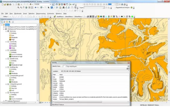
Figure 1 An example of the GIS layer that considers the potential for corroded assets to fail as a result of ground instability
2.3.3
Summary datasets
The Corroded Asset Failure - Ferrous map (summary) comprises one GIS layer called
‘Ferrous_failure_summary’ that considers the potential for corroded assets to fail as a result of
ground instability. This summary map provides an overview of the susceptibility to failure as a
result of the combined effect of aggressive soils and ground movement, but it does not indicate
which hazards are potentially present (Figure 2).
Figure 2 An example of the summary GIS layer that considers
the potential for corroded assets to fail as a result of ground instability3
Using the dataset
3.1
GIS SET-UP
Load the layer files or shape files into the GIS software. We recommend importing the layer file
(if using ArcGIS) as this ensures that the
colour and layout of the layers appear as intended. For other GIS packages, import the layers manually. A .CSV file is provided with the recommended legend colours.The GIS should appear as shown Figure 1.
Make sure the required data layer is present. For the summary map, the following GIS layer should be present:• Ferrous_failure_summary
For the detailed map, the following GIS layer should be present:
• Ferrous_failure
If you need support setting up the GIS, please contact [email protected].
Pan to a location of interest and view each dataset sequentially, following the flow chart shown
in Figure 3.
9
3.2
EXPLANATION OF SUB-LAYERS
Explanations of the field descriptions for the ‘ferrous_failure’ summary field are provided in Table 1. Explanations of the descriptions in the corrosivity, compress, swell, collapse, runsand, landslide and soluble sub-layers are provided in Tables 2 to 8.
Table 1 Summary sub-layer – Description of attributes
Attributes Definition
Unlikely Corrosive ground conditions and ground instability are unlikely to occur simultaneously and thus it is unlikely that corroded ferrous assets will fail due to ground movement. Note that iron corrosion can occur in all soils, but the aggressiveness of the soil is unlikely to be enhanced in these areas.
Low Corrosive ground conditions and ground instability may occur and thus there is a low potential that corroded ferrous assets will fail. Moderate Corrosive ground conditions and moderate ground instability may
occur and thus there is a moderate potential that corroded ferrous assets will fail.
High Corrosive ground conditions and potentially significant ground instability may occur and thus a higher potential that corroded ferrous assets will fail.
Table 2 Corrosivity (Corrosiv) sub-layer – Description of attributes
Attributes Definition
Unlikely Ground conditions beneath top soil unlikely to cause corrosion to iron Possible Ground conditions beneath top soil may cause corrosion to iron Likely Ground conditions beneath top soil are likely to cause corrosion to
iron
Table 3 Compressibility (Compress) sub-layer – Description of attributes
Attributes Definition
Unlikely Corroded underground assets unlikely to be affected by compressible ground.
Low Low potential for corroded underground assets to fail due to this hazard. Slight possibility of compressible ground.
Moderate Moderate potential for corroded underground assets to fail as compressible ground is probably present.
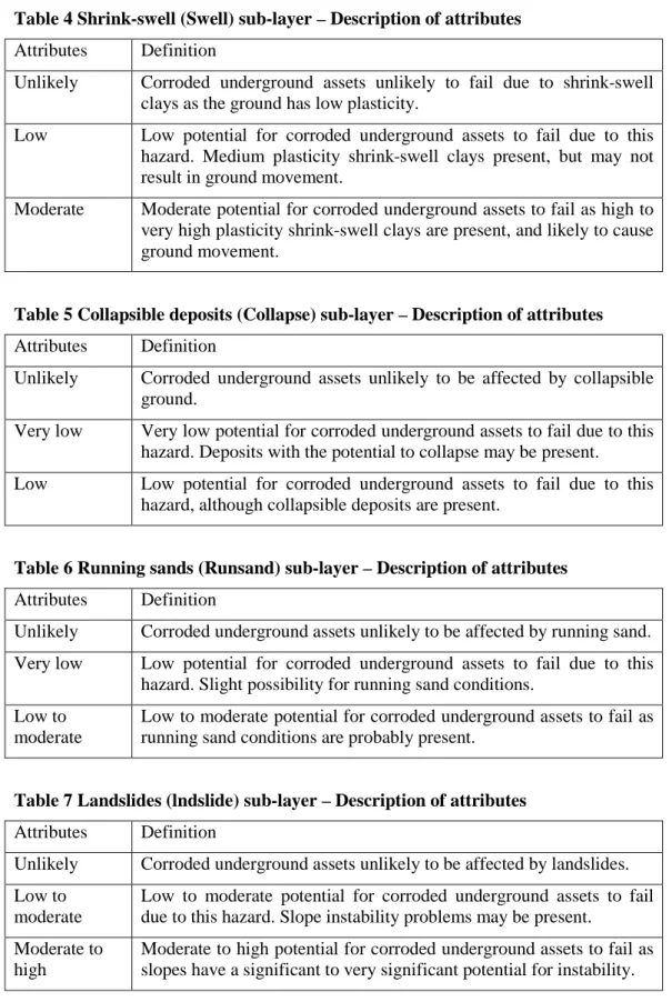
Table 4 Shrink-swell (Swell) sub-layer – Description of attributes
Attributes Definition
Unlikely Corroded underground assets unlikely to fail due to shrink-swell clays as the ground has low plasticity.
Low Low potential for corroded underground assets to fail due to this hazard. Medium plasticity shrink-swell clays present, but may not result in ground movement.
Moderate Moderate potential for corroded underground assets to fail as high to very high plasticity shrink-swell clays are present, and likely to cause ground movement.
Table 5 Collapsible deposits (Collapse) sub-layer – Description of attributes
Attributes Definition
Unlikely Corroded underground assets unlikely to be affected by collapsible ground.
Very low Very low potential for corroded underground assets to fail due to this hazard. Deposits with the potential to collapse may be present.
Low Low potential for corroded underground assets to fail due to this hazard, although collapsible deposits are present.
Table 6 Running sands (Runsand) sub-layer – Description of attributes
Attributes Definition
Unlikely Corroded underground assets unlikely to be affected by running sand. Very low Low potential for corroded underground assets to fail due to this
hazard. Slight possibility for running sand conditions. Low to
moderate
Low to moderate potential for corroded underground assets to fail as running sand conditions are probably present.
Table 7 Landslides (lndslide) sub-layer – Description of attributes
Attributes Definition
Unlikely Corroded underground assets unlikely to be affected by landslides. Low to
moderate
Low to moderate potential for corroded underground assets to fail due to this hazard. Slope instability problems may be present.
Moderate to high
Moderate to high potential for corroded underground assets to fail as slopes have a significant to very significant potential for instability.
11
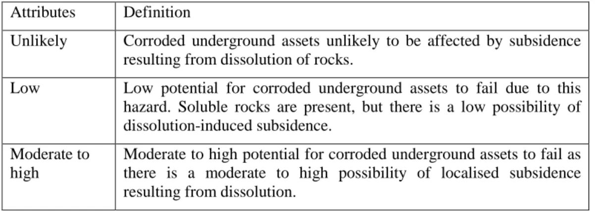
Table 8 Dissolution (soluble) sub-layer – Description of attributes
Attributes Definition
Unlikely Corroded underground assets unlikely to be affected by subsidence resulting from dissolution of rocks.
Low Low potential for corroded underground assets to fail due to this hazard. Soluble rocks are present, but there is a low possibility of dissolution-induced subsidence.
Moderate to high
Moderate to high potential for corroded underground assets to fail as there is a moderate to high possibility of localised subsidence resulting from dissolution.
4
What information does the dataset provide?
4.1
OVERVIEW
This section describes the subsurface property datasets included in the Corroded Asset Failure - Ferrous
map.
4.1.1
Summary map
The summary layer provides an overview of the susceptibility of corroded ferrous assets to fail due to ground movement. It is derived from the datasets described in Sections 4.1.2 to 4.1.8.
4.1.2
Corrosivity
The aggressiveness of the soil to ferrous assets depends on the soil characteristics. Corrosion is more likely to occur where some or all of the following conditions coexist:
• drainage is poor;
• low resistivity;
• pH is either low or high, and
• primary or secondary sulphides or sulphates are present
The corrosivity layer is based on the CIPRA ratings for assessing the corrosive properties of soils. It includes weighted scores for resistivity, soil alkalinity and acidity, moisture or the hydrological properties of parent materials, redox status, and the presence of sulphides/sulphates (Tye et al., 2011).
This component data layer is derived from the BGS Corrosivity (ferrous) dataset. Information about the original dataset can be viewed at: http://www.bgs.ac.uk/products/geohazards/corrosivity.html.
4.1.3
Soluble rocks
Some types of ground contain layers of material that can dissolve in underground water. This can cause underground cavities to develop. The ground above cavities can collapse, resulting in subsidence. More commonly, changes in ground or surface water flow can flush away unconsolidated sediment, potentially leading to the collapse of overlying materials also leading to subsidence at the surface. If such subsidence occurs, the ground around underground assets can move causing corroded assets to fail. If the underground asset in question is a pipe containing liquid, leaking water can increase dissolution or flushing of unconsolidated sediments, leading to a potentially more significant hazard.
This component data layer is derived from the soluble rocks layer of the BGS GeoSure dataset. This data layer has been reclassified to provide an indication of the potential for corroded ferrous assets to fail as a result of ground movement due to dissolution. Information about the original dataset can be viewed at: http://www.bgs.ac.uk/products/geosure/soluble.html.
4.1.4
Landslides
A landslide is an outward and downward movement of material on a slope, due to the force of gravity. A slope is under stress from gravity but will not move if its strength is greater than this stress. If the balance is altered so that the stress exceeds the strength, then movement will occur. If movement does occur, underground assets could be damaged resulting in failure of that asset. If the underground asset in question is a pipe containing liquid, leakage could alter the strength of the deposit, leading to a more significant subsidence hazard.
This component data layer is derived from the landslide layer of the BGS GeoSure dataset. This data layer has been reclassified to provide an indication of the potential for corroded ferrous assets to fail as a result of ground movement due to landslide. Information about the original dataset can be viewed at: http://www.bgs.ac.uk/products/geosure/landslides.html.
Landslide hazards present along the coastline may be under-represented in this dataset due to inaccuracies in the digital elevation model along the coastline.
4.1.5
Compressible ground
Many geological deposits contain water-filled pores. When the ground is compressed by a building or other load, the water in the pore space can be squeezed out, causing the ground to compress. This may cause uniform or non-uniform settling, resulting in tilting, cracking or distortion of underground assets, particularly if they are corroded. If the underground asset in question is a pipe containing liquid, leakage could alter the strength of the deposit, leading to more significant ground movement.
This component data layer is derived from the compressible ground layer of the BGS GeoSure dataset. This data layer has been reclassified to provide an indication of the potential for corroded ferrous assets to fail as a result of ground movement due to compressibility. Information about the original dataset can be viewed at: http://www.bgs.ac.uk/products/geosure/compressible.html.
4.1.6
Swelling clays
Clays that are susceptible to shrink and swell, change volume significantly according to how much water they contain. All clay deposits change volume as their water content varies, typically swelling in winter and shrinking in summer, but some do so to a greater extent than others. Contributory circumstances include the change in moisture content brought about by drought, leaking pipes, tree roots drying out the ground, or changes to local drainage patterns, such as the creation of soakaways. Shrinkage may remove the support from underground assets such as pipes or foundations, whereas clay expansion may lead to uplift or lateral stress on part or all of an asset; any such movement may cause cracking and distortion. If the asset in question is a pipe that leaks, the water added to the ground may cause additional swelling, possibly causing further differential uplift.
This component data layer is derived from the shrink-swell layer of the BGS GeoSure dataset. This data layer has been reclassified to provide an indication of the potential for corroded ferrous assets to fail as a result of ground movement due to swelling clay. Information about the original dataset can be viewed at: http://www.bgs.ac.uk/products/geosure/shrink_swell.html.
4.1.7
Running sands
Running sand conditions occur when loosely-packed sand, saturated with water, flows into an excavation or other type of void. The pressure of the water filling the spaces between the sand grains reduces the contact between the grains causing them to be carried along by the flow. This can lead to subsidence of the surrounding ground. Running sand can result in ground instability for underground assets in two ways; first, sand may run into a void removing the support from beneath an underground asset and secondly if a failed pipeline asset is leaking, the flow of water may cause sands to flow, thereby resulting in subsidence of surrounding ground.
This component data layer is derived from the running sand layer of the BGS GeoSure dataset. This data layer has been reclassified to provide an indication of the potential for corroded ferrous assets to fail as a result of ground movement due to running sand. Information about the original dataset can be viewed at: http://www.bgs.ac.uk/products/geosure/running_sand.html.
13
4.1.8
Collapsible ground
Collapsible ground comprises certain fine-grained materials with large pore spaces. Such deposits can collapse when they have been loaded and then become saturated by water. If the ground below a building collapses it may cause the building to sink. If the collapsible ground is variable in thickness or distribution, structures may suffer from distortion, tilting or cracking. Underground assets may be affected by such movement, particularly where corroded. If the underground asset in question is a pipeline that leaks, the additional water may accentuate the ground stability issue resulting in more widespread breakages.
This component data layer is derived from the collapsible ground layer in the BGS GeoSure dataset. This data layer has been reclassified to provide an indication of the potential for corroded ferrous assets to fail as a result of ground movement due to collapsible ground. Information about the original dataset can be viewed at:
http://www.bgs.ac.uk/products/geosure/collapsible.html.
4.2
DATA SUMMARY
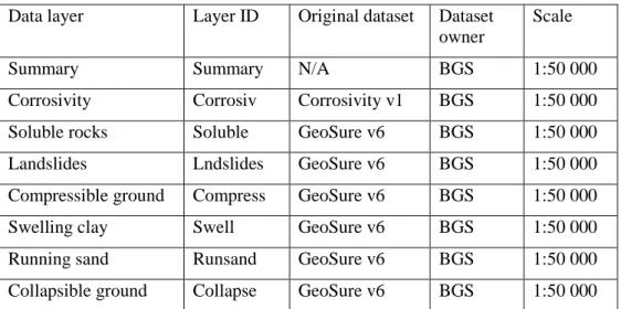
The original datasets used in the creation of the Corroded Asset Failure - Ferrous map are detailed in Table 9.
Table 9. Details of the original datasets used in the Corroded Asset Failure - Ferrous map
Data layer Layer ID Original dataset Datasetowner
Scale
Summary Summary N/A BGS 1:50 000
Corrosivity Corrosiv Corrosivity v1 BGS 1:50 000
Soluble rocks Soluble GeoSure v6 BGS 1:50 000
Landslides Lndslides GeoSure v6 BGS 1:50 000
Compressible ground Compress GeoSure v6 BGS 1:50 000
Swelling clay Swell GeoSure v6 BGS 1:50 000
Running sand Runsand GeoSure v6 BGS 1:50 000
Collapsible ground Collapse GeoSure v6 BGS 1:50 000
5
Technical Information
5.1
PRE-REQUISITE REQUIREMENTS
To use the Corroded Asset Failure - Ferrous map, a computer with vector-based GIS software is required.
It is highly beneficial to have a topographic GIS layer. If unavailable, see the Ordnance Survey website (http://www.ordnancesurvey.co.uk/) for the provision of OpenData.
5.2
CREATION OF THE DATASET
The ‘Ferrous_failure’ dataset is directly derived from the datasets listed in Table 9. The polygons in the original datasets were reclassified with three attributes (e.g. see Tables 2 to 8) and neighbouring polygons with the same attribute were merged.
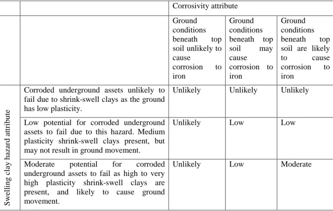
The summary map was developed to provide an overview of the relative potential for corroded assets to fail due to ground instability. To create this summary map, matrices were created for each hazard as shown (for example) in Table 10. For each hazard attribute, the susceptibility for ferrous asset failure was rated for each corrosivity rating. This provides an indication of the likelihood that an asset in a soil of X corrosivity will fail due to a hazard with a potential to occur of Y. If for example, a location had a
moderate potential for corroded assets to fail due to swelling clays, and the ground conditions were unlikely to be corrosive, the susceptibility of corroded assets to fail due to swelling clay would be unlikely (although they could fail due to ground instability alone). Conversely, if at the same location, the ground conditions were likely to cause corrosion to iron, the susceptibility of corroded assets to fail given the swelling clay conditions would be moderate.
Table 10 The swelling clay-corrosivity matrix used in the creation of the summary map.
Corrosivity attribute Ground conditions beneath top soil unlikely to cause corrosion to iron Ground conditions beneath top soil may cause corrosion to iron Ground conditions beneath top soil are likely to cause corrosion to iron S w ell in g c la y h az ar d a ttr ib u te
Corroded underground assets unlikely to fail due to shrink-swell clays as the ground has low plasticity.
Unlikely Unlikely Unlikely
Low potential for corroded underground assets to fail due to this hazard. Medium plasticity shrink-swell clays present, but may not result in ground movement.
Unlikely Low Low
Moderate potential for corroded underground assets to fail as high to very high plasticity shrink-swell clays are present, and likely to cause ground movement.
Unlikely Low Moderate
Six matrices were created for each of the six hazards considered. The summary map was generated by reporting the most susceptible rating from all matrices at any one location.
5.3
SCALE
The Corroded Asset Failure - Ferrous map is produced for use at 1:50 000 scale providing 50 m ground resolution. The mapping scales on which the original geological linework are based are shown in Appendix 1.
5.4
DATASET HISTORY
BGS is strategically surveying and resurveying areas of Great Britain, improving and updating the geological maps. It is anticipated that a new version of the dataset will be released once a significant proportion of the underlying dataset has changed. This report describes the first version of the Corroded Asset Failure - Ferrous map, generated during 2013.
5.5
COVERAGE
The data covers Great Britain, but not the Isle of Man.
5.6
DATA FORMAT
The Corroded Asset Failure - Ferrous map has been created as vector polygons, which are available in a range of GIS and CAD formats, including ArcGIS (.shp) and MapInfo (.tab).
15
5.7
LIMITATIONS
• The corrosivity element of the dataset considers the potential for geological units to produce conditions that are corrosive to buried ferrous assets. It does not consider the effect on pipes of corrosive liquids that may be transported by pipes.
• The Corroded Asset Failure - Ferrous map has been developed at 1:50 000 scale and must not be used at high resolution.
• The Corroded Asset Failure - Ferrous map is based on, and limited to, an interpretation of the records in the possession of the British Geological Survey at the time the dataset was created.
• The dataset is based on published data and expert judgement, but was not derived from data showing incidences of corroded ferrous asset failure as this was not available. BGS would be interested in using such data to test and inform the methodology; please get in touch with [email protected] if you would like to discuss this further.
• Where geological units comprise multiple lithologies, a precautionary approach is taken and the potential for corrosion and movement is based on the worse case.
• This dataset is not an alternative for a ground investigation.
• Site observations represent the properties of the ground more accurately than the data provided by the Corroded Asset Failure - Ferrous map.
• Other more specific and detailed ground instability information may be held by BGS, and an assessment of this could result in a different outcome.
• An indication of potential natural ground instability does not necessarily mean that a location will be affected by ground movement or subsidence. Such an assessment can only be made by
inspection of the area by a qualified professional.
6
Licensing Information
The British Geological Survey does not sell its digital mapping data to external parties. Instead, BGS grants external parties a licence to use this data, subject to certain standard terms and conditions. In general, a licence fee will be payable based on the type of data, the number of users, and the duration (years) of a licence.
All recipients of a licence (potential licensees) are required to return a signed digital data licence document to us before authorisation for release of BGS digital data is given.
In general terms, a BGS digital data licensee will be permitted to:
• make internal use of the dataset(s)
• allow a specified number of internal users to access/use the data (the number of users will be agreed with the licensee and specified in the licence document) for the purposes of their day-to-day internal activities
• reproduce extracts from the data up to size A3 for use in external analogue (paper/hard copy) or non-queryable electronic (e.g. secured .pdf) format: to meet a public task duty; fulfil a statutory requirement; and/or as part of academic or other non-commercial research But will not be permitted to:
• provide a bureau service for others or incorporate the data in the generation of products or services for commercial purposes
• sell, assign, sublicense, rent, lend or otherwise transfer (any part of) the dataset(s) or the licence
• place (any part of) the dataset(s) on the Internet
The BGS is committed to ensuring that all the digital data it holds which is released to external parties under licence has been through a robust internal approval process, to ensure that geoscientific
standards and corporate quality assurance standards are maintained. This approval process is intended to ensure that all data released: (i) is quality assured; (ii) meets agreed BGS data management
standards; (iii) is not in breach of any 3rd party intellectual property rights, or other contractual issues (such as confidentiality issues) that would mean that release of the data is not appropriate.
When the BGS digital datasets are revised any upgrades will be automatically supplied to the licensee, at no additional cost. Most geological map datasets are revised on a periodic rather than on an annual basis, so licensees will not automatically receive a new dataset each year.
These are general comments for guidance only. A licensee of BGS's digital data is provided with full details of the basis on which individual BGS datasets licensed to them are supplied.
If you have any doubts about whether your proposed use of the BGS data will be covered by a BGS digital licence, the BGS Intellectual Property Rights (IPR) section will be happy to discuss this with you and can be contacted through the following email address: [email protected]. BGS IPR will usually be able to provide reassurance that the licence will cover individual user requirements and/or to include additional 'special conditions' in the licence documentation, addressing specific requirements within BGS's permitted usage.
References
Dearden, R.A., Tye, A.M., and Marchant, A., 2014. User guide for the Pipe Leakage Impacts map. British Geological Survey, Open Report, OR/14/010.
Eidinger, J.M. 1998. Water-distribution system In: The Loma Prieta, California, Earthquake of October 17, 1989-Lifelines. A.J. Schiff (ed), US Geological Survey Professional Paper 1552-A. pp. 63-78.
Makar, J.M. 2000. A preliminary analysis of failures in grey cast iron water pipes. Engineering Failure Analysis. 7: 1, pp43-53.
Tye et al. 2011. User guide for the British Geological Survey Corrosivity (ferrous) dataset. British Geological Survey. Open Report OR/11/023
17
Appendix 1
Appendix 2
Creation of the corrosivity dataset
The dataset was created by scoring five corrosive properties and assigning scores to the BGS
Parent Material polygons according to an adapted Cast Iron Pipe Research Association dataset
(CIPRA, 1964). The five parameters that are scored are:-
Soil pH
Soil-parent materials pH scores have been divided into three classes.
1.
Soil pH values > 8.5
2.
Soil pH values < 4.5
3.
Soil pH values > 4.5 and < 8.5.
Moisture
Soil moisture was based on its texture as stated within the Parent Material database. Three
classes were scored
1.
Poor drainage, continuously wet
2.
Fair drainage, generally moist
3.
Good drainage, generally dry
Soil Redox status
Soil redox status was largely based on soil texture information contained within the Parent
Material Database. Three classes were outlined for this soil property.
1.
Well oxidised soils,
2.
Soils prone to seasonal anaerobic conditions
3.
Very wet or waterlogged soils such as peat or saltmarsh soils.
Resistivity
Information was obtained from a resistivity model developed by BGS. Resistivity modelling has
been undertaken for all the LEX_RCS codes in the Midlands of England as part of an earlier
study. This data was then used to inform other LEX_RCS codes outwith this area. Five factors
have been identified from which resistivity values have been modelled. The factors are:
1.
Clay mineral content
2.
Porosity
3.
Saturation
4.
Pore water resistivity Ohm.m
5.
Material factor based on the shape of the particles and pores.
Presence of Sulphides and Sulphates
This was based on data in the BGS LEX_RCS database, the National Geotechnical Properties
Database and through extensive expert knowledge within the BGS and the literature (e.g.
Czerewko & Cripps, 2006; Forster
et al
. 1995). The presence of primary sulphides in soils and
parent materials are typically associated with mudstones, Cretaceous and Tertiary clays, coal
seams as well as waterlogged soils such as peat and estuarine and river alluvium. Primary
sulphates are found typically in the evaporite deposits of the Permo-Triassic and part of the
Jurrasic periods. Secondary sulphates are found where sulphides have been oxidised leading to
formation of sulphate ions. Further information on sulphide and sulphate relating to concrete is
in the Building Research Establishment publication SD1 (BRE, 2001).
19
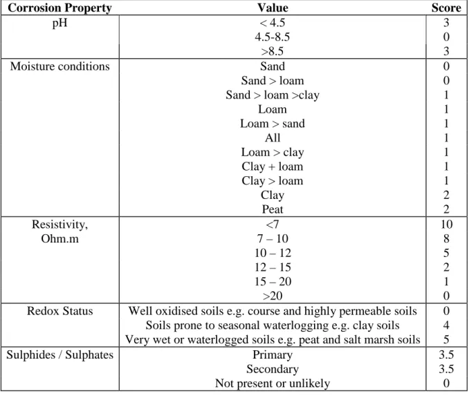
The scoring system in Table A has been used to assign values to the polygons represent the
different parent materials held within the BGS Parent Material dataset.
Table A. Scoring system applied to the Parent Material polygons.
Corrosion Property
Value
Score
pH
< 4.5
3
4.5-8.5
0
>8.5
3
Moisture conditions
Sand
0
Sand > loam
0
Sand > loam >clay
1
Loam
1
Loam > sand
1
All
1
Loam > clay
1
Clay + loam
1
Clay > loam
1
Clay
2
Peat
2
Resistivity,
Ohm.m
<7
10
7 – 10
8
10 – 12
5
12 – 15
2
15 – 20
1
>20
0
Redox Status
Well oxidised soils e.g. course and highly permeable soils
0
Soils prone to seasonal waterlogging e.g. clay soils
4
Very wet or waterlogged soils e.g. peat and salt marsh soils
5
Sulphides / Sulphates
Primary
3.5
Secondary
3.5
Not present or unlikely
0
The final score for each polygon within the dataset are created by summing all the individual
scores for all five corrosive properties (as shown in the table above).
The original CIPRA scoring scheme suggested that any soils with a combined score exceeding
10 were likely to be corrosive. Soils were thus given one of two scores, <10 or >10. However, a
third category has been included for those values around the score of ‘10’ as parent materials that
may require additional examination. Table B describes the colour coding and recommendations.
Table B Scoring system used in the final corrosivity dataset.
CLASS SCORE Ground
Conditions
Recommendation Backfill Colour
coding
Typical Material Description
CLASS SCORE LEGEND RECOMMENDA BACKFILL
1 <9 Ground conditions beneath topsoil are unlikely to cause corrosion to iron Special protection probably not required, unless the ground is clay
or peat or likely to contain saline water (estuarine or marine) if so Do not use peat or salty materials for backfill. Only use clay materials if they do not contain sulphide or
Yellow Most rocks e.g.
sandstone, limestone, chalk, igneous and metamorphic rocks,
boulders, cobbles, gravel, sand and silt
see class 3. sulphate crystals or are of low pH 2 9 - 11 Ground conditions beneath topsoil may cause corrosion to iron Special protection probably required if materials at site are clay, peat or likely to contain
saline water (estuarine or marine). If so see
class 3 Do not use peat or salty materials for backfill. Only use clay materials if they do not contain sulphide or sulphate crystals or are of low pH Do not use peat or salty materials for backfill. Only use clay materials if they do not contain sulphide or sulphate crystals or are of low pH
Green Mostly ‘clays’ and mudstones with relatively low clay size
content and do not contain iron sulphide
or calcium sulphate. 3 >11 Ground conditions beneath topsoil are likely to cause corrosion to iron Special protection probably required if materials at site are clay, mudstone, peat or likely to contain saline water (estuarine or marine). If so, further ground investigation is required to assess whether the hazard exists. Do not use peat or salty materials for backfill. Only use clay materials if they do not contain sulphide or sulphate crystals or are of low pH Do not use peat or salty materials for backfill. Only use clay materials if they do not contain sulphide or sulphate crystals or are of low pH
Blue A variety of material types depending on the
lithostratigraphical classification The following indicate
corrosivity hazard:
i) Grey to black clay, brown near surface. May be mudstone at depth. May contain white or translucent ‘soft’ crystals (gypsum)
at a few metres depth.
ii) Red clay or mudstone, may contain
white or translucent ‘soft’ crystals (gypsum)
at a few metres depth
iii) Peat. iv) Contains saline