39 Page 39-46 © MAT Journals 2019. All Rights Reserved DOI: http://doi.org/10.5281/zenodo.2639954
Abstract
Tungsten inert gas (TIG) welding is broadly useful in manufacturing process. The present work carried on the optimization of weld process parameters with Taguchi approach for the deformation control applied to Austenitic stainless steel 316 structures of 8.5 mm thickness with two pass TIG weld process. Taguchi is applied for the optimization of weld parameters control. In this study, the distortion of TIG welding process was evaluated using weld current, weld angle and the weld speed as the key parameters. ANOVA was perfumed to obtain significant parameter which gives the percentage contribution of each process parameter under operating condition.
Keywords: GTAW, austenitic stainless steel, distortion, Taguchi method, ANOVA analysis, parameter optimization
INTRODUCTION
Tungsten inert-gas (TIG) welding or gas tungsten arc welding (GTAW) is an inert-gas shielded arc welding process using non-consumable electrode. The electrode may also contain 1 to 2% thorium oxide mixed along with the tungsten with 0.15 to 0.40% zirconium oxide. The pure tungsten is less expensive but they will carry less current. The thorium tungsten electrodes carry high currents and more desirable because they can strike and maintain a stable arc with ease. The zirconia added tungsten electrodes are better than pure tungsten but they in farrier to throated tungsten electrode.
A typical tungsten inert-gas welding setup
is shown in Fig. 1. It consists of a welding torch as the center of which is the tungsten electrode. The inert-gas is supplied to the welding zone through the annular path surrounding the tungsten electrode to effectively displace the atmosphere around puddle. The smaller weld torches may not be provided with any cooling devices for the electrodes.
Power sources
The power sources used are always of the constant-current type. Both direct current (DC) and another current (AC) power supplies can be used for TIG welding. When DC is used, the electrode can be negative (DCEN) or positive (DCEP). (Serope Kalpakjian, 2006) [8].
40 Page 39-46 © MAT Journals 2019. All Rights Reserved Figure 1: TIG welding process.
This work is taken up as there are many variables and there is enough scope to study TIG welding. Using Taguchi’s method, a set of experiments are designed at different levels of weld parameters to obtain weld distortion. Analysis of variance and signal-to-noise ratio of robust design were employed to investigate the influence of different welding conditions on weld distortion. This is a field that has been discussed due to its use in electrical appliances and automobile industries, Aero Space industries and following are some important observations reported by researchers.
Deepak Malik et. al [1], Angular deformation has positive effect with increase in length of plates and diameter of electrode.
Mamatha K et. al [2], the optimization of welding input parameters lead to
determining the best settings and tolerances for Xs to optimize Ys, thus reducing the welding angular distortion of fillet weld of deck height.
S Akellaa, et. al [3], design of experiments towards the distortion optimization caused by butt welding. It was found from these experiments that root gap has a major contribution of 43% and weld current of 36% influence on distortion.
Liang Tian et. al [4], Welding experiment is performed to verify the accuracy of the FE model developed. It is found that the angular distortion first increases to its maximum value at the threshold of heat input, then decreases with the further increasing of heat input, while the transverse shrinkage increases with the increasing of heat input continuously.
41 Page 39-46 © MAT Journals 2019. All Rights Reserved
Mr. L. Suresh Kumar et. al [6], the ultimate load of TIG welded specimen is 57600 N, whereas for the MIG welded specimen is 56160N. Therefore, we can say that TIG welded specimen can bear higher loads than MIG welded specimen. The ultimate tensile strength of TIG welded specimen is 675.22MPa, whereas for the MIG welded specimen is 652.029N/mm square. Therefore, we can say that TIG welded specimen has higher tensile strength.
STAINLESS STEEL
Austenitic is the most broadly utilized sort of hardened steel. It has a nickel substance of any rate of 7%, which makes the steel structure completely austenitic and gives it flexibility, a substantial size of administration temperature, non-attractive properties and great weld capacity. The scope of utilizations of austenitic tempered steel incorporates house products, compartments, modern funneling and vessels, compositional veneers and constructional structures. Austenitic evaluations are those compounds which are usually being used for spotless applications. The austenitic evaluations are not attractive. The most well-known austenitic composites are iron-chromium-nickel steels and are broadly known as the 300 arrangement. The austenitic treated steels, in light of their high chromium and nickel content, are the most consumption safe of the impeccable gathering giving uncommonly fine mechanical properties. They can't be solidified by warmth treatment, yet can be solidified fundamentally by chilly working. The
however are most set apart in the austenitic evaluations. They can be abridged in five points:
Stainless steels work-harden considerably. Stainless steels have low thermal conductivity.
Stainless steels have high toughness. Stainless steels watch out to be sticky. Stainless steels have poor chip-breaking characteristics As the treated steel is characterized in various classifications like austenitic, ferrite, martens tic and so forth, from this we have picked austenitic hardened steel.
EXPERIMENTS
TIG welding was carried out with 316 SS samples of 100mm X 50mm X 8.5mm of each and the final sample with size of 100mm X 100mm X 8.5mm. The 316 SS samples are fabricated with V grove design (groove angle of 60, 70·and 80) design edge preparation with 1.5mm root gap and 1.5mm root face joined with two pass TIG welding process. The distortions are observed in all the samples and are measured with vernier height gauge on surface measurement table. The current variation was 125 to 175Amps.
Experimental Setup
The welding process was carried out using TIG M-400 (50-400 amp). The chemical composition of the work material is shown in Table 1. Table 2 Shows the actual welded samples used for joining TIG welding for different range of weld parameters.
42 Page 39-46 © MAT Journals 2019. All Rights Reserved
Figure 2: Weld specimen. Figure 3: Welding machine with specimen. Table 1: Chemical property.
Element Details Required value in % Observed Value in %
Carben 0.080 MAX 0.026 Silicon 0.750 MAX 0.745 Manganese 2.00 MAX 0.947 Phosphorus 0.045 MAX 0.026 Sulphur 0.030 MAX 0.006 Chromium 16.000 To 18.000 17.630 Nichel 10.000 To 14.000 11.890 Molybdenium 2.000 To 3.000 2.219 Nitrogen 0.100 MAX 0.030 IDENTIFICATION OF FACTORS
Control factors and noise factors are two factors used in Taguchi’s approach to identify the optimal process settings that
are minimally sensitive to noise. Control factors are generally controlled during the manufacturing while noise factors are often uncontrollable.
Table 2: Parameter and factor.
Parameter Code Level 1 Level 2 Level 3
Current A 130 A 155 A 18 A
Speed B 65 mm/min. 75 mm/min. 85 mm/min.
Groove angle C 65· 75 85·
In the present work, welding current, welding speed and groove angle were considered as control factors and they varied at three levels as shown in Table 2. L9 orthogonal array was found out to be
appropriate for the selected level and three interactions involving in the table were considered. Signal-to-noise ratio for every combination of weld parameters was calculated and shown in Table 3. Table 3: Experimental tested data.
Sr.no. Current Groove angle Speed(mm/min) Distortion(mm) s/n ratio
1 130 65· 65 2.810 -5.1536 2 130 75· 75 3.925 -9.3225 3 130 85· 85 2.773 -4.9742 4 155 65· 75 2.725 -4.7358 5 155 75· 85 3.025 -6.1285 6 155 85· 65 3.405 -7.6223 7 180 65· 85 2.225 -6.9466 8 180 75· 65 3.178 -10.0431 9 180 85· 75 3.575 -8.2155
43 Page 39-46 © MAT Journals 2019. All Rights Reserved
Degree of freedom associated with any SS will always be one less than the number of observations whose squares are summed. Here, there are 3 observations considered in computing SS and hence degree of freedom is 2 in present case.
Error variance or error mean square is calculated by dividing the lowest value of Sum of Squares (SS) by its degree of freedom.
F-test is used to determine which process parameters have a significant effect on the quality characteristic. The variance ratio denoted by F is given by:
A larger value of F indicates that the effect of that factor is very large as compared to error variance. The larger the contribution of a particular factor to the total sum of squares, the larger is the ability of that factor to . This is expressed in terms of Percent Contribution (%P) which is calculated as follows:
RESULT AND DISCUSSION ANOVA Analysis
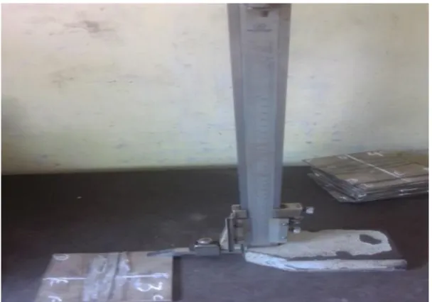
The analysis of variance is the statistical treatment most commonly applied to the results of the experiment to determine the percent contribution of each factors. Study of ANOVA table for a given analysis helps to determine which of the factors need control and which do not shown in below figure 4.
44 Page 39-46 © MAT Journals 2019. All Rights Reserved Figure 4: Measuring distortion on welded part conditions.
Figure 5: Main effects plot for weld distortion. According to this main effect plot Fig. 5,
the optimal for minimum welding distortion are:
Welding current at level 3 (175ampere) Groove angle at level 2 (70·Degree) Welding speed at level 1(60mm/min.)
45 Page 39-46 © MAT Journals 2019. All Rights Reserved observations for this parameter shows a
better level of significance of percentages. TIG welding for SS 316 have resulted with effect of each parameter contribution as following manner.
Current contributes28.23% Angle contributes40.52%
Welding speed contributes13.19%
CONCLUSION
The present experiment will be addressed the angular distortion during welding.
Tungsten inert gas welding on an austenitic stainless steel 316 plate has been controlled by experimental data. The effect of welding parameter
(speed, current and angle of groove) are find.
From experimental result parameter angle has major effect of weld distortion.
This procedure can be effectively used to reduce angular distortion in the design of structures.
Weld distortion analysis for optimum TIG process parameters control with lowest number of experiment.
ACKNOWLEDGEMENT
I would also like to acknowledge with much appreciation the crucial role of Mr. Miteshbhai Patel, the owners of Ashapuri Engineering Pvt. Ltd. for their valuable comments and sharing their time and knowledge on the research carried out during this project. They have contributed a lot towards my understanding and thoughts.
1. Deepak Malik, Sachin Kumar, Mandeep Saini (2014), “Effect of process parameters on angular distortion of gas tungsten arc welded SS 302 and MS plate”, Volume 3, Issue 8.
2. Mamatha K, Mr. HV Vasuki, Mr. Jagadish Mogaveera.B, Dr. CK Nagendra Guptha (2014), “ Optimization of MIG welding process parameter to control angular distortion of a fill et welding an earth moving equipment manufacturing plan”, Volume 5, Issue 6.
3. S Akellaa, B Ramesh Kumar (2013), “Distortion Control in TIG Welding Process with Taguchi Approach, advanced materials manufacturing & characterization”, Volume 3, Issue 1. 4. Liang Tian et al. (2011), “Prediction of
transverse and angular distortions of gas tungsten arc bead-on-plate welding using artificial neural network”
5. G Karthik, P Karuppuswamy, V Amarnath (2014), “Comparative evaluation of mechanical properties and micro structural characteristics of 304 stainless steel weldments in TIG and SMAW welding processes”Special Issue 2.
6. Mr. L. Suresh Kumar, Dr. SM Verma, P Radhakrishna Prasad, P Kiran kumar, Dr. T. Siva Shanker (2011), “Experimental Investigation for Welding Aspects of AISI 304 & 316 by Taguchi Technique for the Process of TIG & MIG Welding” Volume 2, Issue 2
7. JJ del Coz Díaz, P Menéndez Rodríguez A, PJ García Nieto, D. Castro-Fresno (2010), “Comparative
46 Page 39-46 © MAT Journals 2019. All Rights Reserved analysis of TIG welding distortions
between austenitic and duplex stainless steels by FEM”, Applied Thermal Engineering, Volume 30, pp. 2448−2459.
8. Serope Kalpakji Anand Steven R. Schmid (2006), “Manufacturing, Engineering and Technology, Fifth Edition.
9. Pearson Education, Inc., Upper Saddle River, NJ ISBN 0-13-148965-8.
AMERICAN STAINLESS STEEL ASSOCIATION
Chemical composition and mechanical property of AISI (ASTM / ASME) and austenitic stainless steel grades.
METALS HANDBOOK VOLUME 6, “Welding, Brazing and Soldering”, American Society for Metals (ASM)
AISI-Welding of stainless steel and other joining methods-A designer’s handbook series N 9002, distributed by
NID-Nickel Development Institute
ASME-IX QW-409.1, “Calculating Heat
Input for welding”
Books
P. N. RAO “A textbook of Manufacturing
Technology Volume-1”, Third Edition, 2011 Tata McGraw Hill Publication
O. P. KHANNA “A textbook of Welding
Technology”, Dhanpat Rai Publications
PHILLIP J. ROSS “A textbook of
Taguchi Techniques for Quality Engineering”, Second Edition by Tata McGraw Hill Publication
Cite this article as:
Vijay Sahu, & Tanmay Awasthi. (2019). Tentative Analysis of Welding Deformation of Austenitic Stainless Steel 316 in TIG Welding. Journal of Recent Trends in Mechanics, 4(1), 39–46. http://doi.org/10.5281/zenodo.2639954