Contents lists available atScienceDirect
Corrosion Science
journal homepage:www.elsevier.com/locate/corsci
Corrosion behaviour of nitrided ferritic stainless steels for use in solid oxide
fuel cell devices
Manuel Bianco
a,*
, Stephane Poitel
b, Jong-Eun Hong
c, Shicai Yang
d, Zhu-Jun Wang
e,
Marc Willinger
e, Robert Steinberger-Wilckens
f, Jan Van herle
aaGroup of Energy Materials, Inst. Mech. Eng, EPFL Valais, CH-1951, Sion, Switzerland bElectron Spectrometry and Microscopy Laboratory, EPFL, CH-1015, Lausanne Switzerland
cFuel Cell Laboratory–Korea Institute of Energy Research, 152 Gajeong-ro, Yuseong-gu, Daejeon, 34129, Republic of Korea dTeer Coatings Ltd, West Stone House, West Stone, Berry Hill Industrial Estate, Droitwich, WR9 9AS, UK
eFritz Haber Institute of the Max Planck Society, Department of Inorganic Chemistry, Faradayweg 4–6, 14195, Berlin, Germany
fCentre for Fuel Cell and Hydrogen Research–School of Chemical Engineering, University of Birmingham, Edgbaston, Birmingham, B15 2TT, UK
A R T I C L E I N F O Keywords:
High temperature corrosion Oxide coatings
Stainless steel TEM Nitriding
A B S T R A C T
Plasma nitriding was applied to ferritic stainless steel substrates to improve their performances as interconnects for solid oxide fuel cell devices. The samples underwent electrical conductivity test and SEM/EDS, TEM/EDS, environmental-SEM analyses. Thefirst stages of corrosion were recorded in-situ with the e-SEM. Nitriding is effective in limiting the undesired chromium evaporation from the steel substrates and accelerates the corrosion kinetics, but its influence of the electrical conductivity is ambiguous. No intergranular corrosion is found in the steel substrate after long time operation. Nitriding helps commercially competitive porous coating to improve chromium retention properties of metal interconnects.
1. Introduction
Solid oxide fuel cells are highly efficient electrochemical devices able to convert chemical energy into heat and electricity [1], with electrical efficiency higher than 60 % [2]. In commercial applications, individual SOFcells are stacked together and separated via shaped metal sheet, the metal interconnect (MIC).
The MIC fulfills fundamental tasks: it mechanically sustains the cell stacking, collects the produced electrical current and keeps air and fuel separated. A SOFC system works at 700−900 °C (depending on the cell materials) for, for commercial viability, at least 40000 h. In these challenging conditions, steel corrosion is one of the main processes to control as it can cause both electrical and mechanical failure; thermally grown oxides (TGOs) are the least conductive layers in the system and the presence of brittle phases can lead to delamination.
Specific ferritic stainless steels such as Crofer 22 APU [3] and Sandvik Sanergy HT [4] have been developed for SOFC application. These steels contain a high level of chromium, to ensure fast and homogenous surface passivation, and reactive elements (RE) [5], to control the oxide growth rate. A chromium oxide or manganese-chro-mium oxide [6] layer guarantees the corrosion resistance of the alloy. However this solution has a drawback, as the chromium volatile species
[7] produced at high temperature and in humid atmosphere [8] poison the perovskite materials [9] at the air side of the cell, leading to blocking of the cell redox reaction with time [10].
Hence, protective coatings are introduced on the alloy surface to mitigate Cr evaporation [11], with MnCo-spinel coatings being cur-rently the preferred solution. Denser coatings provide better barrier properties [12], therefore deposition methods like PVD and APS have delivered the best results. Notably, Co-based spinels deposited using PVD provide excellent electrical performance coupled with chromium evaporation barrier properties. Coupling of a specific alloy composition and protective coating fully satisfies the needs for long SOFC device lifetime, but the cost of this technology is too high for SOFC commer-cialization, considering that a MIC could account for up to 30 % of the stack manufacturing costs [13].
As a consequence, cheaper materials are considered: low Cr-content alloys such as AISI441/K41 have been introduced and low temperature deposition techniques like wet powder spraying are used. The result is an active researchfield where there is still space for alternative mate-rials and methods. In this context, the present paper presents results obtained from MIC solutions containing nitrided steel substrates.
Nitriding of metal interconnects have already been explored in polymer exchange membrane (PEM) fuel cells to substitute graphite
https://doi.org/10.1016/j.corsci.2019.108414
Received 18 October 2019; Received in revised form 25 December 2019; Accepted 27 December 2019
⁎Corresponding author.
E-mail address:manuel.bianco@epfl.ch(M. Bianco).
0010-938X/ © 2020 The Authors. Published by Elsevier Ltd. This is an open access article under the CC BY-NC-ND license (http://creativecommons.org/licenses/BY-NC-ND/4.0/).
is therefore difficult.
Research about sensitization [16] in ferritic stainless steel (FSS) is closer to the application described in the present study. In the second part of the 80’s Nickel price increased of ca. 500 % in less than one year, forcing steel makers to look for alternatives to austenitic stainless steels (ASS). In particular, automotive industries needed alloys for exhaust systems, able to withstand high temperature. FSS have good corrosion properties at high temperature but the mechanical properties are in-ferior to austenitic stainless steels and if welded they might suffer from intergranular corrosion (IGC): Cr thermodynamically prefers to react with C and N. These precipitates at the grain boundaries of the welded, heat-affected region will scavenge Cr, leading to IGC and material failure [17–19]. Nevertheless, since the operating conditions for the automotive industry are again different from those in SOFCs, this branch of investigation is not sufficiently representative either to de-scribe the behaviour of the material considered in this work.
Hence, even though nitrided stainless steels are not new as such, the utilization of nitrided ferritic stainless steels in SOFC working condi-tions (700 °C) has not been studied yet. Nitriding as pre-processing for SOFC MIC interconnects is a new approach. This manuscript vestigates if and how nitriding can improve the lifetime of metal in-terconnects. In particular it aims to understand how it influences the corrosion process.
2. Materials and experiments
Three ferritic stainless steels were investigated in this study: Crofer 22 H, Sandvik Sanergy HT and K41 (or AISI 441). Compositions are presented inTable 1.
Crofer 22 H and Sandvik Sanergy HT have been developed for SOFC application. Their Cr contents are high enough to withstand the cor-rosion process at high temperature. They are enriched in reactive ele-ments such as Mn, Nb, and Mo. Niobium improves the steel creep re-sistance, promoting Laves phases [2]. Manganese improves the thermally grown oxide electrical conductivity. The drawback of this high alloying is cost, at least tenfold higher than commercial K41.
The steel coupons used in this study were supplied by SOLIDPower S.p.A. and Teer coating Ltd.
The surfaces of half of the stainless steel samples tested were treated using high power pulsed plasma nitriding (HPPPN) process at TeerCoatings Ltd. (UK), to evaluate the properties of microstructure and scale growth of nitrided steel substrates under high temperature oxi-dation. The steel plates (100 × 100 mm) were placed on a substrate
properties. The method is a modification of the 4-probe test,
with two coupons are assembled facing each other. One coupon is the nitrided steel with a coating on top, while the other one is made of palladium, in between there is a Cr gathering layer of (La,Sr,Co) per-ovskite. Knowing the applied current density and acquiring the voltage drop between the two coupons, the ohmic loss is obtained. The Cr re-tention property instead is measured as the amount of chromium inside the perovskite. It was of interest to compare these two characteristics with non-nitrided (standard) substrates.
A portion of the small samples was instead investigated through an in-situ oxidation process. In-situ oxidations were observed with a modified FEI Quanta 200 environmental scanning electron microscope (ESEM). One side of the thin sample was heated with a laser while the other side was scanned by the electron beam. The temperature was monitored with a thermocouple welded onto the observed surface. A massflow controller adjusted an O2 flow of 5Nml/min into the mi-croscope chamber close to the sample. With a differential pumping system, this lead to a O2pressure of 30 Pa (0.3 mbar) in the chamber. The tracking of the area of interest was performed manually. The ob-servation window width was 8.2 microns.
The heating of these samples was conducted as follows: (1) tem-perature increase in 30 s to the next step, (2) temtem-perature stabilization during 6 min while recording 6 images. The targeted temperature steps were: 200 °C, 300 °C, 400 °C, 450 °C, 500 °C, 550 °C, 600 °C, 650 °C, 700 °C. At 700 °C, the scan speed was set to 88 s/image and this state was maintained for one hour. Then, temperature was maintained 10 more minutes to record micrographs of the zone of interest at different magnifications (65, 125, 250, 500, 1 000, 2 000, 5 000, 10 000, 30 000). The temperature wasfinally decreased to room temperature in one minute.
After such in-situ observation, lamellae were extracted from each sample with a focussed ion beam (FIB)-SEM and subsequently observed with a transmission electron microscope (TEM). This allowed the ob-servation of the sub-surface microstructure from 5 to 10μm under the surface. TEM-energy dispersive x-ray spectroscopy (EDS) mapping was conducted on each lamella to compare the diffusion of elements and the obtained microstructure. In order to obtain more information on the metallic phases, ASTAR analysis from Nanomega was used on the ni-trided samples. Data acquisitions were conducted for an hour on a square area of 1μm2.
The scale thickness calculation was performed through a Matlab routine that considered images pretreated with Adobe Photoshop, in order to segment and insulate the scale layer.
Table 1
Elemental compositions of metal interconnect substrates (weight percentage).
Fe Cr C Mn Si Al Mo Nb Ti W
K41/AISI 441 [20] Bal. 18 0.01 0.3 0.35 – – 0.45 0.17 –
Sanergy HT [21] Bal. 21.2 0.04 0.3 0.12 0.02 0.96 0.71 0.09 –
3. Results and discussion
3.1. Electrical resistance and Cr rentention
The MICs have to collect the electricity produced by the SOFC, therefore low electrical resistance is desired. At the same time, the in-terconnect should not poison the cathode perovskite material by re-leasing chromium vapours [24]. The area specific resistance (ASR (Ω*cm2)) is the parameter used to quantify the electrical performances; when divided by the scale thickness, it returns the material apparent resistivity. To quantify if and how much chromium migrated from the steel substrate to the perovskite, the material in contact with the ni-trided samples was analysed by EDS.
Figs. 1 and 2compare the results of ASR and Cr retention perfor-mances obtained from nitrided and standard (without nitriding) steel samples.
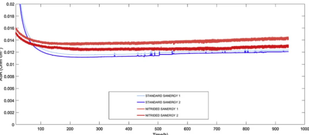
Fig. 1presents the ASR time evolution (performed at 700 °C in air) for standard and nitrided Sandvik Sanergy samples coated with Fe-doped MCO. The ASR values after 1 000 h of exposure are slightly higher for the nitrided samples and the trends are similar. Not all the tested nitrided samples showed higher ASR values than the standard samples [25] (the whole set of data can be found in the link in the Appendix). It is necessary to evaluate ASR values after at least 1000 h of testing to ensure that all main temperature-driven phenomena stabilize. In nitrided substrates, this stabilization period appears shorter and less pronounced than that in standard substrates. This is visible as the
plateau being reached after≈100 h by nitrided substrates (Fig. 1). Nitrided stainless steels were also used as the metal substrate in real SOFC interconnects tested in SOFC devices up to 10 000 h. Voltage degradation values inTable 2indicate how much a certain single repeat unit contributes to the SOFC stack performance. The two single re-peating units (interconnect + cell) containing the nitrided substrate behave better than those with a standard stainless steel substrate.
Regarding the chromium blocking function, nitrided samples con-stantly showed improved behaviour. This was particularly evident in Fig. 1.Area specific resistance curves as a function of exposure time in air at 700 °C for physically vapour deposited MnCo2O4coatings on Sandvik Sanergy HT stainless steel substrate. Each experiment had two repetitions for statistical reliability.
Fig. 2.EDS linescans taken on perovskite materials, simulating a SOFC cathode, in contact for 1 000 h in air at 700 °C with non-nitrided (left) and nitrided (right) samples.
Table 2
Voltage degradation rates of complete interconnect + cell repeating units tested inside 6-cell SOFC stacks. A value of < 0.5 %kh−1is considered a threshold for a viable unit. WPS: wet powder spray, APS: atmospheric plasma spray, MCO: MnCo2O4, MCF: MnCo1.6Fe0.4O4. The RUs are listed according to their position in the stack: from the bottom to the top.
MIC Coating Comp. Steel substrate Degradation (%kh−1)
WPS MCO #1 MnCo2O4 K41/AISI441 0.72
NITRIDED APS MCO #1
MnCo2O4 Nitrided K41/
AISI441
0.34
WPS MCO #2 MnCo2O4 K41/AISI441 0.67
APS MCF #1 MnCo1.6Fe0.4O4 K41/AISI441 1.14
APS MCF #2 MnCo1.6Fe0.4O4 K41/AISI441 0.64
NITRIDED APS MCF #2
MnCo1.6Fe0.4O4 Nitrided K41/
AISI441
behaviour of the steel substrates, particularly in thefirst stage of op-eration. The next paragraph presents the corrosion evolution of the steel substrates and identifies the species formed during aging.
3.2. Microstructure evolution
To help distinguish between nitrided and standard (non-nitrided) steel substrates in the microstructure analysis results, the former will be labelled withN,the latter withSt.
It is known that chromia scale growth on stainless steel substrates containing nitrogen has faster kinetics [26]. Several experiments con-ducted in controlled atmospheres confirmed this: non-metals such as nitrogen can create ordered structures in the metal substrate with some of the alloying elements, chromium in particular [27]. This arrange-ment induces a higher presence of chromium at the surface, therefore when the material oxidizes, the generated chromium oxide nuclei are more numerous than with a standard substrate [28,29]. More nuclea-tion sites lead to the formanuclea-tion of numerous oxide grains with small size. In addition, chromium ions diffuse faster through the grain boundaries which results in irregular scale growth on nitride samples, a porous containing structure
Fig. 3presents the in-situ ESEM results on standard and nitrided stainless steel substrates (K41, Crofer 22 H and Sandvik Sanergy HT) after oxidation at different temperatures.
These image frames are taken from videos which can be found in the Appendix. Thefirst column ofFig. 3represents the moment when oxide grains become visible on the surface, around 300 °C for K41 and Crofer 22 H and around 400 °C for Sandvik Sanergy HT. These values have to be considered as average, as the heating of the samples may not have been homogenous. The third column presents the morphologies oxi-dised at 700 °C; this temperature was taken as thefinal point to com-pare it to results obtained in ASR tests [25]. An intermediate tem-perature value (≈550 °C, middle column) helps to follow the oxidation process.
There is a difference in the corrosion process between the standard and the nitrided substrates. With the latter, the scale on nitrided sam-ples is porous and irregular, with the oxidation products resembling flakes, whereas in the standard substrates the scale is made of prismatic crystals, as expected [30].
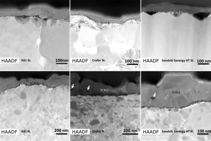
This sponge-like structure on the nitrided substrates comes from the preferential growth of chromium oxide through grain boundaries [27]. The microstructures inFig. 3were qualitatively obtained from the top surface of nitrided and standard stainless steels. Micrometric la-mella cross sections were subsequently extracted from the ESEM ob-served samples and studied by TEM. High-angle annular dark field images (HAADF) of the cross sections are shown inFig. 4. The dotted lines indicate the oxide grown on the steel substrates. (The top part of the samples is a carbon layer deposited for protective purpose during the FIB extraction of the lamella and therefore not further considered.) Looking at these cross sections, the oxide layer grown on nitrided substrates is confirmed to have experienced irregular growth. However, it is not possible to verify that the thicker regions match with the grain
at the beginning of the corrosion process. This pores confirms a lateral growth of the scale grains.
The absence of such pores in the standard substrates accounts for the faster kinetics of scale growth in the nitrided substrates. This being coherent with what is described above: the presence of nitrogen induces a chromium enrichment below the steel surface which in turn enhances the oxidation process occurring preferentially at the grain boundaries. From the grain boundaries then, the oxides expand laterally covering all the surface (cfr. videos in the appendix).
The elemental characterization of these lamellae (Fig. 5) indicates complex corrosion products for nitrided samples, with iron oxide as outer scale and chromium oxide adherent to the steel substrate. The nitrided steel substrate does not present inward corrosion, i.e. convex regions growing inside the metal. In contrast, a beginning of inward corrosion is visible in the K41St. substrate. The absence of inward scale growth is a relevant difference with the typical iron breakaway corro-sion process.
EDS quantitative analysis on the ESEM-aged samples indicates dif-ferent iron contents in the thermally grown oxides inTable 3.
The data indicate a more intense outward diffusion of iron on ni-tridided substrates. This result suggests that chromium in the initial oxidizing phase reacts preferentially with nitrogen, leaving the steel substrate unpassivated. Iron therefore could migrate outward and form an iron oxide scale as can be seen inFig. 5. However, the absence of an enhanced inward corrosion suggests that this process took place for a short period only. In ASR-aged nitrided substrates as well (1 000 h, 700 °C), iron is found in the MCO coating, even though in smaller content (4–5 at.%), confirming the outward migration of Fe. Such iron outward diffusion was also observed in the protective coating deposited on nitrided interconnects for a SOFC stack that was tested for 10000 h, where the Fe percentage measured was around 25 at.%.
The other element found in the scale is manganese, which is ex-pected and coherent with the common oxidation behaviour of steels in use for SOFCs [31]. Manganese in fact helps to mitigate chromium evaporation and scale growth; in addition, the mixed spinel of chro-mium and manganese has higher electrical conductivity than chromia alone [32].
The complete scale in the nitrided samples is thus made of a layer of chromium nitrides, followed by chromium-manganese oxide andfinally Fe oxides on top.
Considering the metal substrate, the presence of nitride precipitates is the main difference between standard and nitrided substrates. The behaviour of nitrogen in the metal substrate is still under investigation in the literature, as it is influenced by temperature and alloying ele-ments concentration [33,34]. Notably, it is important to understand how the nitrogen evolves and interacts with the lattice and with Fe and the alloying elements, in this case chromium. When nitrogen diffuses into the steel substrate itfirst reacts with the alloying element and then is dissolved in the matrix lattice without mechanical deformation. For both processes, a limit dictated by thermodynamic equilibrium exists. However, in reality, an excess of nitrogen is always present which mechanically stresses the metal substrate [35]. In addition, the ferritic
phase and the nitrides have different crystal lattices. Ferriteαhas a bcc structure, providing a coefficient of thermal expansion compatible with the SOFC components. Cr2N instead has a hexagonal lattice causing a tension in the metal matrix. Finally, at temperatures higher than 800 °C, nitrogen could stabilize the austenitic phase also with high chromium concentration [36].
Most of the studies encountered in literature are interested in de-scribing the microstructural condition of the steel substrate im-mediately after the nitriding process. In this sense the samples tested for a few hours in the e-SEM are closer to this condition. As the main practical application is to modify the mechanical properties of the steel, there is no technological interest to understand the evolution of nitrided steel substrates for long exposure at high temperatures.
The consequence is that only a few studies describe aging of nitrided substrate in testing conditions close to those of this study (high chro-mium nitrided steels operated at high temperatures) [37,38]. Miyamoto et al. present a distinction between‘disk’and‘rod’shaped chromium nitride precipitates. Moving from the steel surface, i.e. closer to the nitriding source, towards the centre of the sample, the rod shape be-comes prevalent. The density of the precipitates decreases as well fur-ther from the steel surface. The composition of precipitates tends to follow the morphology: CrN phase is typically disk shaped while Cr2N is rod shaped. However, some rod shaped CrN is found as well: a com-position change from Cr2N to CrN is the proposed cause. In addition, Cr2N grows when there is a minor presence of nitrogen; this is the reason why Cr2N is encountered in greater depth in the steel substrate, close to the edge of the nitrogen diffusion region.
Fig. 6shows two cross sections taken from ASR-aged substrates of nitrided AISI441/K41 and Sandvik Sanergy HT for 1000 h, in which both substrates carried a porous protective coating. Here Crofer 22 H is not reported, as its composition is similar to Sandvik Sanergy HT.
In the steel substrate cross sections, three regions with distinct morphologies can be observed. The layer immediately under the scale (belt 1) contains spherical precipitates and no visible segregation at the
grain boundaries. Below belt 1, there is a region with a high density of small and elongated precipitates inside the grains and at the grain boundaries (belt 2). Finally, in the core of the stainless steel, the biggest and widest particles are distributed (belt 3). Belt 2 and 3 are in a good agreement with what was previously described in the literature [37]. The precipitates closer to the surface are thin, elongated and numerous while those deeper into the steel centre are bigger and rod-shaped. Belt 1 conversely includes rounded precipitates. The average particle size in belt 1 increases with exposure time: in nitrided K41 stainless steel substrate after aging at 700 °C for 1 h (ESEM samples), 1 000 h (ASR tested samples) and 10 000 h (SOFC stack samples), the particle sizes were estimated to be < 0.005, 0.71 and 2.1μm average respectively. In addition, the thickness of belt 1 region increases with the exposure time at high temperature: 19μm at 1000 h and 51μm at 10000 h. This suggests an Ostwald ripening process for belt 1.
The nitrided precipitates found in the e-SEM-aged lamellae indicate both rod and round shape as well in the region close to the steel surface. Fig. 7also reveals that the nitrided precipitates are Cr2N. From the TEM-EDS analyses the atomic percentage ratio between chromium and nitrogen is 2.8, 1.8 and 2.7 for K41, Crofer 22 H and SS HT substrates respectively. The grains that lay below the measured one might have influenced the measurement, inducing the higher amount of chromium. Additionally, the cross sections of the interconnect components (10 000 h in stack operation) present similar morphology with that of ASR-and ESEM-samples (not shown here).
To better investigate which phases are present after aging, a TEM Astar identification was performed: SAED analysis was conducted on several grains, close to the surface, on standard and nitrided K41, Crofer 22 H and SSHT. Only ferritic iron was identified. The number of grains analysed depends on the quality of the TEM samples, which in turn depends on the FIB lamella extraction.
No austenitic phase could be identified in K41 N, nor in Crofer 22 H N. However, 3 grains out of 7 were identified as potential auste-nitic phase in nitrided SSHT. In order to obtain better statistical results, Fig. 4.TEM High-angle angular dark-field images (HAADF) of lamellae taken from the E-SEM observed samples.
the lowest reliability of the obtained results (the ASTAR software in-dicates how much a phase identification is reliable) as seen onFig. 7. The complexity of the system and the techniques make it difficult to clearly evaluate the presence of austenite. Indeed, even for simpler systems like binary Fe-Cr alloy [39], the diffraction interpretation is difficult. Automated crystal orientation mapping for TEM is also chal-lenging [40] and unfortunately did not provide the desired answers for this study.
A known drawback of the presence of nitrogen and carbon is in-tergranular corrosion (IGC). At high temperatures, nitrogen interacts preferentially with chromium to create CrN or Cr2N. In addition, this reaction is reported to take place principally at the grain boundaries because of the nitrogen segregation [41]. As a result, the metal sub-strate is depleted from chromium and passivation properties are dete-riorated, with a preferential corrosion at the grain boundaries. In all the ASR-tested samples (1000 h) or real MIC operated samples (10 000 h) that were observed, no IGC was encountered, as the percentage of chromium contained in the steel substrate is high enough that it can compensate for the local loss due to reaction with nitrogen. The chro-mium cations diffuse from the bulk of the grain towards the depleted regions, restoring the passivation properties. This is visible also in the line scan result ofFig. 8 (taken in belt 1), with the green line being constant in the metal regions surrounding the Cr2N particles. In addi-tion, the high temperature helped to quickly redistribute chromium cations in the substrate.
Another possible issue for the steel substrate is the transformation from ferritic to austenitic phase within the nitrogen-rich region. This might be a problem for SOFC applications as austenitic stainless steel has a coefficient of thermal expansion higher than those of the cell components, which could potentially cause physical deformation on the cell up to breaking. According to the Fe-Cr-N phase diagram [42], high operating temperature (above 800 °C) coupled with high content of
standard non-nitrided steel substrates.
Additional uncoated, nitrided and non-nitrided ferritic stainless steel samples underwent an in-situ oxidation process inside an en-vironmental SEM. The superficial growth of the scale was recorded. TEM lamellae were extracted from the ESEM samples to examine the subsurface.
The nitriding process hardly affected the electrical conductivity (ASR) measurements of the steels (Fig. 1), and led to a shortening of the time to stabilise ASR values.
Nitriding resulted in an improvement of chromium retention, par-ticularly on the steels with porous protective coatings. In the case of dense coatings, nitriding indicated no further improvement. Since porous protective layers are generally produced by simple wet chemical coating processes, at costs lower than that of physical vapour deposition or thermal plasma spraying, nitriding could provide an alternative so-lution for commercial application.
Scanning and transmission electron microscopy observations were performed on cross sections taken from standard and nitrided substrates aged for 1, 1 000 and 10 000 h, to examine the corrosion processes inside the nitrided samples.
Microscopy results confirmed faster oxidation kinetics in the ni-trided samples. Nitrogen acts as a chromium scavenger, temporarily depleting the steel substrate and causing a limited iron breakaway corrosion, shown by the presence of Fe traces both in the coating and on top of the scale of uncoated samples. This Fe outward diffusion, how-ever, took place for only a short period. The high content in chromium and the high testing temperature promptly recovered the passivation properties of the steel. In practice, this means that the initial accel-eration of the corrosion kinetics is not harmful for the material, as no traces of intergranular corrosion were encountered in nitrided ferritic stainless steel substrates tested for 1 000 and 10 000 h.
The nitride precipitates in oxidizing atmosphere are identified
Fig. 6.SEM images of cross sections of ASR-tested samples (1000 h, 700C). On the left AISI441/K41, on the right Sandvik Sanergy HT. Each belt indicates a region where the nitride precipitates show a rather homogenous morphology.
mainly as Cr2N and a phase transformation from ferritic to austenitic steel is considered to be unlikely.
Considering all aspects, nitriding is a method to improve the per-formance of low cost commercial ferritic stainless steels used as SOFC interconnects carrying porous coatings resulting from low cost deposi-tion techniques such as wet powder spraying.
Data availability
All data used in this work, raw or processed, required to reproduce these results can be provided upon request by the corresponding au-thor.
Declaration of Competing Interest
The authors declare that there are no conflicts of interest. CRediT authorship contribution statement
Manuel Bianco: Conceptualization, Data curation, Resources, Formal analysis, Investigation, Methodology, Software, Validation, Visualization, Writing - original draft.Stephane Poitel:Data curation, Investigation, Writing - review & editing. Jong-Eun Hong:Writing -review & editing. Shicai Yang: Resources. Zhu-Jun Wang: Investigation. Marc Willinger: Investigation. Robert Steinberger-Wilckens: Funding acquisition, Project administration, Supervision. Jan Van herle:Writing - review & editing, Supervision.
Acknowledgments
The research leading to these results received funding from the
European Union’s Seventh Framework Programme (FP7/2007-2013) through the Fuel Cells and Hydrogen Joint Undertaking under grant agreement no. 325331 for project SCoReD 2:0. Swiss partners are funded from the Swiss State Secretariat for Education, Research and Innovation SEFRI under contract 16.0042.
This work was supported by the AWESOME (Analysis of Solid Oxide Material close to Working conditions by Environmental Scanning Electron Microscopy) project funded by the Swiss National Fund (SNF) under the grant number: 200021176025. The author J.E. Hong also acknowledges thefinancial support from the Technology Development Program to Solve Climate Changes of the National Research Foundation (NRF) funded by the government (Ministry of Science and ICT) of the Republic of Korea (NRF-2017M1A2A2044926).
References
[1] EG&G Technical Services, Fuel Cell Handbook, U.S. Department of Energy, 2004. [2] M. Bertoldi, O. Bucheli, A. Ravagni, Development, manufacturing and deployment
of SOFC-based products at SOLIDpower, ECS Trans. 78 (2017) 117/123. [3] L. Paul, H. Hattendorf, L. Niewolak, B. Kuhn, O. Ibas, W.J. Quadakkers, S. Antonio,
Crofer®22 H - A New High Strength Ferritic Steel for Interconnectors in SOFCs, (2010), p. 30.
[4] A.W.B. Skilbred, R. Haugsrud, Sandvik sanergy HT–a potential interconnect ma-terial for LaNbO4-based proton ceramic fuel cells, J. Power Sources. 206 (2012) 70–76,https://doi.org/10.1016/j.jpowsour.2012.01.101.
[5] S. Chevalier, What did we learn on the reactive element effect in chromia scale since Pfeil’s patent? Mater. Corros. 65 (2013) 109–115,https://doi.org/10.1002/maco. 201307310.
[6] Z. Yang, J.S. Hardy, M.S. Walker, G. Xia, S.P. Simner, J.W. Stevenson, Structure and conductivity of thermally grown scales on ferritic Fe-Cr-Mn steel for SOFC inter-connect applications, J. Electrochem. Soc. 151 (2004) A1825–A1831,https://doi. org/10.1149/1.1797031.
[7] H. Yokokawa, T. Horita, N. Sakai, K. Yamaji, M.E. Brito, Y.-P. Xiong, H. Kishimoto, Thermodynamic considerations on Cr poisoning in SOFC cathodes, Solid State Ion. 177 (2006) 3193–3198,https://doi.org/10.1016/j.ssi.2006.07.055.
[8] A. Yamauchi, K. Kurokawa, H. Takahashi, Evaporation of Cr2O3 in atmospheres Fig. 7.Processed result from Astar analysis on Sandvik Sanergy HT substrate. Left image: virtual brightfield from the diffraction central spot. Right: phase map; dark blue is ferrite (96 %), light blue is austenite (0.7 %) and red is chromium nitride (3.3 %). (For interpretation of the references to colour in thisfigure legend, the reader is referred to the web version of this article).
Fig. 8.Left: SEM backscattered electrons micrograph of nitrided Sandvik Sanergy HT substrate tested for 1000 h. On the right: quantitative analysis (at.%) of the linescan on the SEM picture.
Avenue Columbus, OH 43201, 2014. https://energy.gov/sites/prod/files/2014/06/ f16/fcto_battelle_cost_analysis_apu_feb2014.pdf (accessed February 10, 2017). [14] T.J. Pan, B. Zhang, J. Li, Y.X. He, F. Lin, An investigation on corrosion protection of
chromium nitride coated Fe–Cr alloy as a bipolar plate material for proton exchange membrane fuel cells, J. Power Sources 269 (2014) 81–87,https://doi.org/10.1016/ j.jpowsour.2014.06.147.
[15] M.P. Brady, K. Weisbrod, C. Zawodzinski, I. Paulauskas, R.A. Buchanan, L.R. Walker, Assessment of thermal nitridation to protect metal bipolar plates in polymer electrolyte membrane fuel cells, Electrochem. Solid-State Lett. 5 (2002) A245–A247,https://doi.org/10.1149/1.1509561.
[16] A.P. Bond, E.A. Lizlovs, Intergranular corrosion of ferritic stainless steels, J. Electrochem. Soc. 116 (1969) 1305.
[17] J.K. Kim, Y.H. Kim, S.H. Uhm, J.S. Lee, K.Y. Kim, Intergranular corrosion of Ti-stabilized 11wt% Cr ferritic stainless steel for automotive exhaust systems, Corros. Sci. 51 (2009) 2716–2723,https://doi.org/10.1016/j.corsci.2009.07.008. [18] J.D. Gates, R.A. Jago, Effect of nitrogen contamination on intergranular corrosion of
stabilized ferritic stainless steels, Mater. Sci. Technol. 3 (1987) 450–454,https:// doi.org/10.1179/mst.1987.3.6.450.
[19] X. Huang, D. Wang, Y. Yang, Effect of precipitation on intergranular corrosion re-sistance of 430 ferritic stainless steel, J. Iron Steel Res. Int. 22 (2015) 1062–1068, https://doi.org/10.1016/S1006-706X(15)30113-8.
[20] K41 technical data sheet, ArcelorMittal, n.d. http://www.aperam.com/uploads/ stainlesseurope/TechnicalDataSheet/FT_K41X_Eng.pdf (accessed November 15, 2017).
[21] J. Tallgren, M. Bianco, O. Himanen, O. Thomann, J. Kiviaho, J. van Herle, Evaluation of protective coatings for SOFC interconnects, ECS Trans. 68 (2015) 1597–1608,https://doi.org/10.1149/06801.1597ecst.
[22] VDM Metals, Crofer 22 H material data sheet, VDM Metals (2010). [23] J. Tallgren, O. Himanen, M. Bianco, J. Mikkola, O. Thomann, M. Rautanen, J.
Kiviaho, J.V. Herle, Method to Measure Area Specific Resistance and Chromium Migration Simultaneously from Solid Oxide Fuel Cell Interconnect Materials, Fuel Cells. 0 (n.d.). doi:10.1002/fuce.201800169.
[24] B.K. Kim, D.-I. Kim, K.-W. Yi, Suppression of Cr evaporation by Co electroplating and underlying Cr retention mechanisms for the 22 wt% Cr containing ferritic stainless steel, Corros. Sci. (n.d.). doi:10.1016/j.corsci.2017.10.019.
[25] M. Bianco, J. Tallgren, J.-E. Hong, S. Yang, O. Himanen, J. Mikkola, J. Van herle,
2345585.
[31] M. Park, J.-S. Shin, S. Lee, H.-J. Kim, H. An, H. Ji, H. Kim, J.-W. Son, J.-H. Lee, B.-K. Kim, H.-W. Lee, B.-K.J. Yoon, Thermal degradation mechanism of ferritic alloy (Crofer 22 APU), Corros. Sci. 134 (2018) 17–22,https://doi.org/10.1016/j.corsci. 2018.01.022.
[32] W.Z. Zhu, S.C. Deevi, Development of interconnect materials for solid oxide fuel cells, Mater. Sci. Eng. A 348 (2003) 227–243, https://doi.org/10.1016/S0921-5093(02)00736-0.
[33] G. Miyamoto, A. Yonemoto, Y. Tanaka, T. Maki, T. Furuhara, Microstructure and growth kinetics of nitrided zone in plasma-nitrided Fe–Cr alloys, ISIJ Int. 47 (2007) 1491–1496,https://doi.org/10.2355/isijinternational.47.1491.
[34] P. Jessner, M. Gouné, R. Danoix, B. Hannoyer, F. Danoix, Atom probe tomography evidence of nitrogen excess in the matrix of nitrided Fe–Cr, Philos. Mag. Lett. 90 (2010) 793–800,https://doi.org/10.1080/09500839.2010.506425.
[35] M. Jung, S.R. Meka, B. Rheingans, E.J. Mittemeijer, Coupling inward diffusion and precipitation kinetics; The case of nitriding iron-based alloys, Metall. Mater. Trans. A 47 (2016) 1425–1439,https://doi.org/10.1007/s11661-015-3271-z. [36] K. Frisk, A thermodynamic evaluation of the Cr-Fe-N system, Metall. Trans. A 21
(1990) 2477–2488,https://doi.org/10.1007/BF02646992.
[37] G. Miyamoto, A. Yonemoto, Y. Tanaka, T. Furuhara, T. Maki, Microstructure in a plasma-nitrided Fe–18 mass% Cr alloy, Acta Mater. 54 (2006) 4771–4779,https:// doi.org/10.1016/j.actamat.2006.06.006.
[38] R.L. Liu, M.F. Yan, Effects of rare earths on nanocrystalline for nitrocarburised layer of stainless steel, Mater. Sci. Technol. 33 (2017) 1346–1351,https://doi.org/10. 1080/02670836.2017.1289441.
[39] O. Skiba, A. Redjaïmia, J. Dulcy, J. Ghanbaja, G. Marcos, N. Caldeira-Meulnotte, T. Czerwiec, A proper assessment of TEM diffraction patterns originating from CrN nitrides in a ferritic matrix, Mater. Charact. 144 (2018) 671–677,https://doi.org/ 10.1016/j.matchar.2018.07.019.
[40] A. Kobler, C. Kübel, Challenges in quantitative crystallographic characterization of 3D thinfilms by ACOM-TEM, Ultramicroscopy. 173 (2017) 84–94,https://doi.org/ 10.1016/j.ultramic.2016.07.007.
[41] R.J. Hodges, Intergranular corrosion in High purity ferritic stainless steels: effect of cooling rate and alloy composition, Corrosion 27 (1971) 119–127.
[42] S. Hertzman, M. Jarl, A thermodynamic analysis of the Fe-Cr-N system, Metall. Trans. A 18 (1987) 1745–1752,https://doi.org/10.1007/BF02646206.