LIMITING FACTORS AFFECTING STAGE I TREATMENT: A BIOMECHANICAL PERSPECTIVE
Christopher G. Gibson
A thesis submitted to the faculty at the University of North Carolina at Chapel Hill in partial fulfillment of the requirements for the degree of Master of Science in the School of Dentistry
(Orthodontics).
Chapel Hill 2016
© 2016
ABSTRACT
Christopher G. Gibson: Limiting Factors Affecting Stage I Treatment: A Biomechanical Perspective
(Under the direction of Ching-Chang Ko)
Objectives: Stage 1 orthodontic tooth movement plays a critical role affecting the efficiency of treatment. However, the limiting factors to stage I tooth movement are poorly defined. We hypothesize that resistance to sliding (RS) between the archwire and the bracket in Stage 1 therapy can contribute to tooth movement and is dependent upon the hyperelastic behaviors of archwire materials and the type of geometric malalignment. Methods: A device was fabricated that allows manipulation of three brackets into multiple malocclusion scenarios (In-out, rotation, tipping, and vertical step). Using an Instron®, a straight segment of archwire was pulled through each configuration at a constant rate and the force required was recorded. In each malocclusion scenario, a series of data was collected on Resistance to Sliding (RS) related to magnitude of archwire deflection. For each malocclusion scenario, 10 increments were tested, and each sequence was repeated five times. One-way ANOVA and piecewise linear regression analysis were used to analyze the data. Results: Using a 0.016” CuNiTi archwire, critical angles and
ACKNOWLEDGEMENTS
TABLE OF CONTENTS
LIST OF TABLES ... vii
LIST OF FIGURES ... viii
LIST OF ABBREVIATIONS ... ix
LIST OF SYMBOLS ...x
REVIEW OF THE LITERATURE ...1
Prevalence & Significance of Orthodontic Treatment ...1
The Three Stages of Orthodontic Treatment ...1
Friction and RS Studies ...4
Material & Geometry ...5
RS Regions in Tipping ...7
Efficient Tooth Movement ...11
Current Models ...14
Conclusions ...15
References ...17
LIMITING FACTORS AFFECTING STAGE I TREATMENT: A BIOMECHANICAL PERSPECTIVE ...21
Introduction ...21
Brackets and Archwires ...23
Testing Apparatus ...23
Mounting the Orthodontic Bracket ...24
Measuring Resistance to Sliding ...24
Results ...26
Discussion ...28
Conclusions ...30
References ...32
Appendix ...35
Tables ...35
Figures...37
LIST OF TABLES
LIST OF FIGURES
Figure 1 – Illustrated examples of factors limiting stage I treatment ...37
Figure 2 – Bracket dimensions and the critical angle (θc) ...38
Figure 3 – The MSA ...39
Figure 4 – The four simulated malalignment scenarios ...40
Figure 5 – Different response curves observed ...41
Figure 6 – Linear trends observed for each malalignment scenario ...42
LIST OF ABBREVIATIONS
SS Stainless Steel
TMA Titanium Molybdenum Alloy Co-Cr Cobalt-Chromium
LIST OF SYMBOLS
© Copyright Symbol
® Registered Trademark
A REVIEW OF THE LITERATURE
Prevalence & Significance of Orthodontic Treatment
Malocclusion affects a majority of the population; therefore, orthodontic treatment is an extremely important and valuable healthcare service. The 1996 Third National Health and Nutrition Examination Survey (NHANES III), when coordinated with current indices of
treatment needs, shows approximately 57-59% of all Americans possess at least some degree of orthodontic treatment needs.1 Orthodontic treatment can provide significant benefits to the patient. There are several psychosocial problems that can arise from malocclusion, and an association between treatment need and quality of life has been demonstrated.2 Malocclusion can also affect oral function by decreasing the efficiency of oral behaviors such as mastication and speech. There are also several problems that can arise such as soft tissue damage, increased incisor morbidity (resulting from a deep bite), and occlusal trauma from crossbites.3 Considering the cost of therapy and prevalence of treatment needs, Orthodontic treatment’s potential can be estimated as approaching a trillion dollar health care industry. Treatment time, however, is quite lengthy (approximately 2 years per patient), therefore great rewards could be seen by shortening the treatment duration. Technologies have been evolved to shorten time for tooth movement in all stages of treatment. Better understanding the mechanics and dental responses of appliance therapy is critical to this goal.
Contemporary orthodontic mechanotherapy is broken down into three stages: leveling and alignment (Stage I), anterior-posterior molar correction and space closure (Stage II), and a finishing stage (Stage III). Breaking down treatment into these three distinct stages was
originally proposed by Dr. Raymond Begg to aid in utilization of the Begg appliance.4 While the Begg appliance is scarcely used in today’s orthodontics, the staging proposed still holds true with today’s edgewise appliances.3
The goal of the first stage of treatment is to bring the dental crowns into alignment along the arch, level the Curve of Spee, provide coordination between the maxillary and mandibular dental arches. Even though the dental crowns may initially be unaligned, the root apices typically have not deviated from their ideal biological positions. Therefore, dental alignment is best achieved with forces that move the dental crown while leaving the root apex in place. With the advent of superelastic NiTi archwires, an ideal continuous tipping force of 50g can be maintained throughout the alignment process.3 For this reason, superelastic archwires have become the ideal choice for initial alignment. It is critical, however, when utilizing a straight wire technique to understand the potential unwanted force systems generated. The majority of undesired outcomes result from applying a straight wire technique to scenarios of asymmetric crowding, and such cases should be approached judiciously.5
natural eruption of the anterior dentition, producing a “relative intrusion.” In the non-growing patient, relative intrusion is not possible, therefore all the movement is purely posterior
extrusion. In cases where posterior extrusion is not desired, the forces must be localized only to intruding the anterior. This is known as “absolute intrusion,” which requires segmented archwire mechanics and potentially skeletal anchorage to achieve.
The coordination of the dental arches should also be considered, most notably the corresponding widths posteriorly. Transverse expansion of the mandibular dental arch is unstable6, therefore, most treatment options target changing the maxillary dental arch to better conform to the pre-treated mandibular arch. It is also critical to determine whether the
discrepancy is associated with a skeletal incompatibility or dental malpositioning as this will affect treatment modality chosen.3
The second stage of orthodontic treatment is concerned with correction to a Class I molar occlusion and the closure of any remaining space. Molar correction is typically achieved by dental compensations, growth modification, or a combination of two. When these are not enough correct the molar position, or if the esthetic outcome is unacceptable, surgical correction may be utilized.3
across a straight wire segment. Sliding between the archwire and brackets must be possible, therefore, the friction and other phenomena that may hinder successful space closure have been subject to extensive research. Elastic chain and NiTi closing coils are the most common tools for sliding mechanic closure. Both are considered equally effective, however, NiTi coils have been shown to close space faster than elastic chain clinical trials. The decision for utilizing NiTi coils, however, must be weighed with their significantly higher cost.9
The final stage of treatment takes care of the final details to achieve an ideal esthetic and occlusal outcome. Six keys of normal occlusion are typically referenced in assessing the
outcome of treatment. The first two keys, removing rotations and leveling the occlusal plane, were addressed in stage 1. Two more, achieving Class I molar relation and closing all spaces, were addressed in stage 2. The final two keys left to be addressed in stage 3 are crown
angulation and crown inclination.10 Crown angulation refers to the mesial-distal tip of the teeth and proper root alignment. Root parallelism can typically be assessed on a panoramic radiograph and corrected with finishing bends or bracket repositions. Crown inclination refers to the buccal-lingual angulation or torque of the teeth. Inadequate crown inclination can often be seen by the tipping of anterior teeth from closing extraction spaces. The crowns are able to move faster than to roots without the control of a proper couple. This must be corrected using rectangular
Friction is an inevitable phenomena in modern orthodontics using the bracket-archwire system. Its role in orthodontic therapy is a popular and controversial topic. Many have theorized that the presence of friction could significantly affect the teeth’s ability to move effectively. Several factors affect the rate of tooth movement. Tissue health and the periodontium’s
biological response play a critical role;3 however, the mechanics and appliances utilized are the factors most commonly manipulated by the orthodontist. The frictional forces present in the bracket-archwire interface have been recognized in the literature as playing a significant role in the efficiency of tooth movement.12-14
Material & Geometry
There has been a great deal of literature dedicated to better understanding how materials and geometric orientations affect friction in orthodontic treatment. Several different materials are utilized in orthodontic appliances and each exhibit their own inherent roughness and frictional coefficients. In order to better understand how different materials may produce
differing amounts of friction, specular reflectance was used to evaluate the surface roughness of common orthodontic materials. A significant difference in surface roughness was observed with the smoothest material being SS, followed by Cobalt-Chromium, TMA, and NiTi with increasing surface roughness.15
TMA archwires actually showed a higher coefficient of friction than NiTi when pulled against a SS surface. Using scanning electron microscopy and energy dispersive x-ray analysis, it was determined that TMA in contact with SS actually developed metal-metal bonds which had to be broken for sliding to occur, ultimately resulting in the increased RS.16
Utilizing a stainless steel self-ligating bracket, the relation between surface roughness and friction coefficient was reevaluated in a more clinically relevant scenario. Four brackets were arranged to resemble the posterior segment of an average archform. A 1.5mm Curve of Spee was designed into the alignment and artificial saliva was present during sliding. From this experiment no significant difference in the sliding resistance of differing archwires could be detected. SS, TMA and multiple types of NiTi archwires were tested.17
It has also been observed that the combination of materials between archwire and bracket can affect Resistance to Sliding (RS). The same friction response as seen earlier was observed with increasing order: SS, Co-Cr, NiTi, TMA. Changing the bracket material showed a
significant effect on RS. TMA coupled with a SS bracket presented the highest RS. A decrease in overall RS was noted for TMA coupled with multiple types of ceramic brackets, and the greatest decrease was produced with a titanium bracket material. This study provided insight on the importance of matching material types and how differing materials can physically affect surfaces of both archwire and bracket. When materials of differing hardnesses are coupled, it becomes easy to produce surface irregularities and notches within the softer material which ultimately can produce dramatic increases in RS.18
size of bracket slot, and overall width of bracket all effect the RS observed. As archwire size increases in diameter, the resulting RS increases as well. In examining bracket dimensions, RS decreases as bracket slot size goes up, and RS increases with a wider overall bracket. In a tipping study, it was observed that a single tie-wing bracket had the least RS, while a standard width twin tie-wing bracket showed increased RS, and a wide twin tie-wing bracket had the highest RS of the three. These changes in RS are significant as a nearly seven-fold increase was observed between utilizing a 0.018” SS archwire versus a 0.019” x 0.025” NiTi archwire.19
As the study of friction and RS continued it became clear that the alignment of the
archwire in a bracket slot was also important. The angulation of a bracket relative to the archwire produces significant differences in the magnitude of RS. This concept was first evaluated as far back as 1970, when RS was evaluated among several archwire sizes at multiple angulations relative to the bracket slot. A positive relationship was observed between RS and increasing angulation.20 While this study could show the increasing response of RS, it lacked the resolution necessary to show exactly what type of relationship was being observed. The 1970 study utilized four tipping angulations at five degree increments. A later study noticed that there appeared to be a difference in the RS response between small and large bracket-archwire angulations.21 Our current study evaluates several geometric orientation of brackets other than tipping which are outlined in Figure 1.
RS Regions in Tipping
“There is every indication that classical friction controls sliding mechanics below
some critical contact angle, θc. Once that angle is exceeded, however, binding and notching phenomena increasingly restrict sliding mechanics.”
This critical contact angle was theorized to occur at the angulation in which an archwire first contacts the corners of the tie-wings. After thoroughly analyzing the relative dimensions of archwires and brackets an equation for calculating the theoretical critical contact angle was developed:
θc takes into account three geometric values that have been evaluated in previous studies and recognized to have a direct relation with RS. “Size” refers to the archwire diameter, which in previous studies was shown to increase RS with increasing diameter. Referring to Figure 2 it is apparent how a smaller diameter wire would be able to achieve a larger angle relative to the slot before making contact with the tie-wings. “Slot” refers to the bracket’s slot size, which is most commonly 0.018” or 0.022” in contemporary orthodontic therapy. In the same figure it is apparent that by the same logic, increasing the slot size would allow for a greater angle to be achieved before contacting the tie-wings. Finally, “Width” refers the mesial-distal dimension of the bracket and is measured from the outside dimensions of the tie-wings. Reducing this
This critical angle divides the “classical friction” region from that of the “binding and notching phenomena”. Classical friction refers to the commonly recognized Coulomb friction formula:
Where Ff refers to the force of friction, µ is the coefficient of friction, and Fn is the normal force produced by the object to be moved. In an orthodontic scenario, this would mean Fn was the force produced by the ligature pressing the archwire against the bracket slot, and µ was a coefficient determined by the combination of material types between archwire and bracket. A lower coefficient would exist for SS archwire in a SS bracket, while a larger coefficient would exist for a TMA archwire in a SS bracket, as noted in previously reviewed studies. Binding and notching, however, add an extra element to the mix, and therefore, Coulomb’s friction formula is no longer sufficient to calculate RS after the critical angle is reached.
Binding is a term given to the RS phenomena observed once an archwire comes in contact with the bracket tie-wings in a tipping situation. This is common clinical scenario in the space closure phase of orthodontic treatment. Due to force being placed incisal to the center of resistance of the teeth, a moment is produced and tipping towards the space rapidly occurs.18,23 As the archwire contacts the tie-wings, new sources of frictional forces are added to the overall RS (one at each tie-wing contact). The RS experienced at this point is a summation of the classical friction between the base and archwire with the two tie-wing contact-point frictional forces. As tipping increases from this point, the normal force against the bracket base should remain unchanged, while the normal force experienced by the tie-wings will increase
At the point where the angulation of the archwire relative to bracket slot just approaches or slightly exceeds θc, RS becomes a combination of the force from friction and the resistive force produced by binding. Once θ increases to a distinctly larger angle than θc, the significance of the force produced by classical friction rapidly becomes insignificant and the force produced by binding dominates the value of RS. Relatively soon after surpassing θc, the frictional force from the archwire against the slot base is considered negligible.22,25
During binding, no permanent alterations are occurring to the bracket or archwire. After a certain angle, greater than θc,a similar, more dramatic effect is seen as permanent damage occurs to the wire and/or bracket surfaces. This permanent deformation to the archwire is referred to as notching, and it can be observed as microscopic imperfections created in the archwire.
Imperfections in the archwire surface can result in mechanical interlocking of the archwire and bracket slot producing an extraordinary increase in RS. This increase in RS is distinctly greater than that of binding forces.26
Notching is dependent on archwire composition. A higher incidence of notching is encountered with composite archwires as opposed to SS archwires. While the archwire material plays a critical role in the presence of notching, the bracket material composition had an
insignificant impact on notching rates.27 To put the rate of notching into context with each wire type, ceramic wires had three times more notching than SS wires. Additionally, the anatomic region of the dentition influenced notching showing a larger proportion occurring in the anterior region as opposed to the posterior.28
tipping, and translation, cause a type of “sliding wear”. On the other hand, vertical movement such as those involved with occlusal loads lead to fretting wear. Fretting is due to oscillatory movements that lead to surface crack formation and eventual loss of adhesive bonds between opposing materials. In sliding wear, surface damage that occurs with horizontal movement is observed as scratching or scoring, and ‘galling’ in cases of more extensive damage. Galling refers to “extensively penetrating surface damage.28” This occurs when a harder material plows into a softer material.29 This is can be evidenced by a bracket sliding along an archwire.
Depending on the amount of angulation, the leading edge of the bracket will contact the wire, dig into the wire, and release leaving a lunar-shaped defect. Thus, the material properties that are most responsible for the amount of damage is related to their respective hardness levels.28
Efficient Tooth Movement
RS in Stage I may or may not affect the efficiency of tooth alignment. Friction in the bracket-archwire interface and its effects on initial alignment have been a highly debated topic in recent years. Some theories emphasize the idea that minimizing friction between a bracket and wire allow the teeth to slide easily along the archwire and improve the efficiency of alignment.30 It is most commonly proposed that a reduction in friction can be achieved through the use of a self-ligating bracket.14 Other studies have shown no significant difference in efficiency of
alignment between traditional and self-ligating appliances.12,31,32 From an alternative perspective, binding between a wire and bracket potentially could help produce the expansion necessary to allow tooth alignment.
self-ligating brackets were compared to traditionally ligated brackets in terms of the RS
experienced when pulling an archwire through them. For each bracket type, RS was measured in several trials by pulling an archwire through a single mounted bracket with an Instron® machine. The brackets were aligned to produce no binding forces and one bracket was tested at a time. Several archwires, ranging from 0.014” NiTi to 0.019”x0.025” SS, were tested in each bracket type. A significantly lower RS was recorded for self-ligating brackets versus traditionally ligated brackets for all wire types and sizes.33
Some concerns with the previous study were that only classical friction was tested, and in a clinical scenario, malaligned teeth would not allow such an ideal scenario. Pizzoni developed a testing apparatus that allowed tipping of the bracket so RS testing could occur at multiple angles. Again, self-ligated brackets were compared to conventional brackets with multiple archwire sizes and several angles ranging from 0-12. The results showed that a significant decrease in RS for all angles and wire dimensions when passed through a passive self-ligated bracket versus a
conventional bracket. No significant difference was noted between the conventional bracket and the active self-ligated bracket utilized.34
fold decrease in RS over tradition ligation methods. It was concluded that utilizing self-ligating brackets in a malaligned dentition “allows the wire to exploit its mechanical characteristics more efficiently” due to the decreased RS experienced.30
With the claim that self-ligating brackets had the potential to increase treatment
efficiency and decrease treatment time by producing lower overall frictional forces, many studies attempted to determine the validity of this theory. A split mouth study was designed to observe the alignment efficiency of self-ligating brackets versus traditionally ligated brackets. Patients were bonded from the midline of the lower arch with a traditional twin bracket on one side and a Damon 2 passive self-ligating bracket on the other. Alignment indexes were analyzed for both sides at the 10 week and 20 week adjustment appointments. Overall, no statistically significant difference in alignment effectiveness was found.32 This contradicts many of the claims that decreased friction or RS result in a higher efficiency of alignment.
Another study evaluated the efficiency of phase 1 alignment in a randomized control trial of patients using either Damon 3 passive self-ligating brackets or Synthesis conventionally ligated brackets. Models were taken after the first archwire change (moving from 0.014” CuNiTi archwire to a 0.018” CuNiTi archwire) and at the conclusion of leveling and alignment
(placement of a 0.019”x0.025” SS archwire). For this study, all cases had between 5-12mm of mandibular incisor irregularity and extraction of lower premolars was prescribed. At both stages analyzed, no statistically significant difference in the rate of alignment could be observed. (Scott 2008)
presented helped to emphasize the idea that once θc, is passed, the role of classical friction becomes less and less significant.
“With a 7° angulation, the binding made up 80% of the resistance to sliding; when the angle was increased to 13°, binding produced 99% of the resistance to sliding, and friction was not an influence.24”
This concept was shown to not only apply to the traditionally ligated bracket, but also to self-ligated bracket systems. In a 2009 review of RS literature it was shown how without binding present, dramatic differences in RS exist among different bracket types. This is most notably observed in the significantly higher RS of standard-ligation brackets. However, the introduction of binding, by introducing angulation between wire and bracket, rapidly equalizes RS for all bracket systems.35
With binding friction seemingly always present in the true clinical scenario, it may be necessary that some auxiliary force apart from the elastic closing chain is necessary to allow sliding along an archwire. One such theory is that forces such as those created during mastication actually result in a releasing phenomenon that reduces RS by transiently removing binding or notching resistances. Several experiments have been conducted showing this phenomenon.36-38 One such experiment provided an oscillating force on a bracket while the archwire was being pulled through. This oscillating force was intended to mimic the cyclic forces placed on teeth during mastication. In the study, large rectangular SS archwires experienced an 80-85% reduction in RS when external oscillatory forces were present.39
In the recent literature a device was created to help measure, with incredible detail, the forces and moments present in malocclusion scenarios. Utilizing a six-axis load cell, the device can measure the forces and moments in all three dimensions. Translation and rotation stages are also incorporated into the design allowing for single bracket malalignments to be examined in this great level of detail. The experimental critical angle regarding tip and RS collected by this device corroborated Kusy and Whitley’s RS models, and has great potential for testing RS in three dimensions as opposed to the tradition one dimension.40
A similar model was used on an even greater scale when similar six-axis load cells where combined to simulate an entire dental arch. With 14 transducers, a maxillary arch from 2nd molar to 2nd molar can show all the forces and moments present within the entire arch for simulated malocclusion scenarios.41 Using this device, the force/couple systems of a high canine
malocclusion scenario was studied. It was observed that forces and moments only existed at the high canine bracket and the two adjacent brackets. All other brackets registered minimal force in this malocclusion scenario, and binding was only present at the brackets adjacent to the high canine. Reduced forces and moments were observed when using self-ligating bracket compared to traditional elastic ligated brackets. From the data, it was speculated that passive self-ligation’s ability to reduce resistance to wire sliding could ultimately reduce the incidence of undesired loads throughout the dental arch.42-43
Conclusions
that more information in the stage is necessary. Also, there is a great deal of controversy related to how friction effects treatment effectiveness and efficiency. Regardless of the role friction plays in initial alignment, it is critical to understand how friction changes among different
malalignment scenarios. In order to manipulate friction clinically when and why it presents itself.
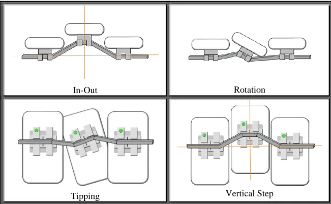
Clinically, impeded tooth movement along an archwire can be attributed to at least four geometric malalignment factors: in-out, tipping, rotation, and vertical step (pictured in Figure 1). Each is considered to be a limiting factor in achieving complete alignment of the dentition. The degree of the malalignment is expected to be associated with the force of RS. Previous studies evaluating friction and RS are limited to stage II treatment goals, focusing on how tipping affects tooth sliding while correcting anterior-posterior discrepancies. It seems logical that many of the same findings could translate well to the mechanics of stage I treatment. Nevertheless, these malalignment factors have not yet been defined with experimental evidence. Being able to understand the limiting factors imposed on the initial stages of orthodontic treatment will help to produce more predictable and efficient tooth movement.
REFERENCES
1. Proffit, William R., H. W. Fields, and L. J. Moray. "Prevalence of Malocclusion and Orthodontic Treatment Need in the United States: Estimates from the NHANES III Survey." International Journal of Adult Orthodontics and Orthognathic Surgery 13 (1998): 97-106. Print.
2. Liu, Z., C. McGrath, and U. Haag. "The Impact of malocclusion/orthodontic Treatment Need on the Quality of Life: A Systematic Review." The Angle Orthodontist 79.3 (2009): 585-91. Print.
3. Proffit, William, ed. Contemporary Orthodontics. 5th ed. Elsevier, 2013. Print.
4. Begg, P. R., and P. C. Kesling. Begg Orthodontic Theory and Technique. Philadelphia: WB Saunders, 1977. Print.
5. Shroff, B., and S. J. Lindauer. "Leveling and Aligning: Challenges and Solutions." Seminars in Orthodontics 7 (2001): 16-25. Print.
6. Little, R. M., R. A. Riedel, and A. Stein. "Mandibular Arch Length Increase during the Mixed Dentition: Postretention Evaluation of Stability and Relapse." American Journal of Orthodontic Dentofacial Orthopedics 97 (1990): 393-404. Print.
7. Proffit, W. R. "Forty Year Review of Extraction Frequency at a University Orthodontic Clinic." The Angle Orthodontist 64.6 (1994): 407-14. Print.
8. Quinn, R. S., and D. K. Yoshikawa. "A Reassessment of Force Magnitude in Orthodontics." American Journal of Orthodontics 88 (1985): 252-60. Print. 9. Dixon, V., et al. "A Randomized Clinical Trial to Compare Three Methods of
Orthodontic Space Closure." Journal of Orthodontics 29 (2002): 31-6. Print.
10.Andrews, L. F. "The Six Keys to Normal Occlusion." American Journal of Orthodontics 62.3 (1972): 296-309. Print.
11.Bolender, Y., et al. "Torsional Superelasticity of NiTi Archwires." The Angle Orthodontist 80 (2010): 1100-9. Print.
12.Scott, P., et al. "Alignment Efficiency of Damon3 Self-Ligating and Conventional Orthodontic Bracket Systems: A Randomized Clinical Trial." American Journal of Orthodontic Dentofacial Orthopedics 134 (2008): 470.e1,470.e8. Print.
13.Tidy, D. C. "Frictional Forces in Fixed Appliances." American Journal of Orthodontic Dentofacial Orthopedics 96 (1989): 249-54. Print.
Straight-15.Kusy, Robert P., et al. "Surface Roughness of Orthodontic Archwires Via Laser Spectroscopy." The Angle Orthodontist (1988): 35-45. Print.
16.Kusy, Robert P., and John Q. Whitley. "Effects of Surface Roughness on the Coefficients of Friction in Model Orhtodontic Systems." Journal of Biomechanics 23.9 (1990): 913-25. Print.
17.Prososki, Robert R., Michael D. Bagby, and Leslie C. Erickson. "Static Frictional Force and Surface Roughness of Nickel-Titanium Arch Wires." American Journal of
Orthodontic Dentofacial Orthopedics 100 (1991): 341-8. Print.
18.Kusy, Robert P., and John Q. Whitley. "Friction between Different Wire-Bracket Configurations and Materials." Seminars in Orthodontics 3 (1997): 166-77. Print. 19.Kapila, Sunil, et al. "Evaluation of Friction between Edgewise Stainless Steel Brackets
and Orhtodontic Wires of Four Alloys." American Journal of Orthodontics 98 (1990): 117-26. Print.
20.Andreasen, George F., and Fernando R. Quevedo. "Evaluation of Friction Forces in the 0.022x0.028 Edgewise Bracket in Vitro." Journal of Biomechanics.3 (1970): 151-60. Print.
21.Frank, Charles A., and Robert J. Nikolai. "A Comparative Study of Frictional Resistances between Orthodontic Bracket and Arch Wire." American Journal of Orthodontics 78.6 (1980): 593-609. Print.
22.Kusy, Robert P., and John Q. Whitley. "Influence of Archwire and Bracket Dimensions on Sliding Mechanics: Derivations and Determinations of the Critical Contact Angles for Binding." European Journal of Orthodontics 21 (1999): 199-208. Print.
23.Loftus, B. P., and J. Artun. "A Model for Evaluation Friction during Orthodontic Tooth Movement." European Journal of Orthodontics 23 (2001): 253-61. Print.
24.Articolo, Laurence C., and Robert P. Kusy. "Influence of Angulation on the Resistance to Sliding in Fixed Appliances." American Journal of Orthodontic Dentofacial Orthopedics 115 (1999): 39-51. Print.
25.Thorstenson, Glenys A., and Robert P. Kusy. "Comparison of Resistance to Sliding between Different Self-Ligating Brackets with Second-Order Angulation in the Dry and Saliva States." American Journal of Orthodontic Dentofacial Orthopedics 121 (2002): 472-82. Print.
27.Zufall, S. W., K. C. Kennedy, and R. P. Kusy. "Frictional Characteristics of Composite Orthodontic Archwires Against Stainless Steel and Ceramic Brackets in the Passive and Active Configurations." Journal of Materials in Medicine 9 (1998): 611-20. Print. 28.Articolo, L. C., et al. "Influence of Ceramic and Stainless Steel Brackets on the Notching
of Archwires during Clinical Treatment." European Journal of Orthodontics 22 (2000): 409-25. Print.
29.Jastrzebski, Z. D. Nature and Properties of Engineering Materials. New York: John Wiley and Son, Inc, 1976. Print.
30.Matarese, Giovanni, et al. "Evaluation of Frictional Forces during Dental Alignment: An Experiment Model with 3 Nonleveled Brackets." American Journal of Orthodontic Dentofacial Orthopedics 133 (2006): 708-15. Print.
31.Miles, Peter G. "SmartClip Versus Conventional Twin Brackets for Initial Alignment: Is there a Difference?" Aust Orthod J 21 (2005): 123-7. Print.
32.Miles, Peter G., Robert J. Weyant, and Luis Rustveld. "A Clinical Trial of Damon 2 Vs Conventional Twin Brackets during Initial Alignment." The Angle Orthodontist 76 (2006): 480-5. Print.
33.Thomas, S., M. Sherriff, and D. Birnie. "A Comparative in Vitro Study of the Frictional Characteristics of Two Types of Self-Ligating Brackets and Two Types of Pre-Adjusted Edgewise Brackets Tied with Elastomeric Ligatures." European Journal of Orthodontics 20 (1998): 589-96. Print.
34.Pizzoni, L., G. Ravnholt, and B. Melsen. "Frictional Forces Related to Self-Ligating Brackets." European Journal of Orthodontics 20 (1998): 283-91. Print.
35.Burrow, S. J. "Friction and Resistance to Sliding in Orthodontics: A Critical Review." American Journal of Orthodontic Dentofacial Orthopedics 135 (2009): 442-7. Print. 36.Liew, C. F., P. Brockhurst, and T. J. Freer. "Frictional Resistance to Sliding Archwires
with Repeated Displacement." Australian Orthodontics Journal 18.2 (2002): 71-5. Print. 37.Sirisaowaluk, N., O. Kravchuk, and C. T. Ho. "The Influence of Ligation on Frictional
Resistance to Sliding during Repeated Displacement." Australian Orthodontic Journal 22.2 (2006): 141-6. Print.
38.Olson, J. E., et al. "Archwire Vibration and Stick-Slip Behavior at the Bracket-Archwire Interface." American Journal of Orthodontic Dentofacial Orthopedics 142 (2012): 314-22. Print.
40.Fathimani, M., et al. "Development of a Standardized Testing System for Orthodontic Sliding Mechanics." Progress in Orthodontics 16.14 (2015): 1-12. Print.
41.Badawi, H. M., et al. "Three-Dimensional Orthodontic Force Measurements." American Journal of Orthodontic Dentofacial Orthopedics 136 (2009): 518-28. Print.
42.Fok, J., et al. "Analysis of Maxillary Arch force/couple Systems for a Simulated High Canine Malocclusion." The Angle Orthodontist 81 (2011): 953-9. Print.
LIMITING FACTORS AFFECTING STAGE I TREATMENT: A BIOMECHANICAL PERSPECTIVE
Introduction
Friction and its role in the initial alignment phase (Stage I) of orthodontic therapy is a controversial topic. Several factors affect the rate of tooth movement. Tissue health and the periodontium’s biological response play a critical role.1 However, these factors are not under the control of the orthodontist who must rely on manipulating mechanics and appliances to affect tooth movement. The frictional forces present in the bracket-archwire interface have been recognized as playing a significant role in the efficiency of tooth movement.2-4
A great deal of literature has been dedicated to better understanding friction and its relation to orthodontic treatment. Several different materials are utilized in orthodontic appliances and each exhibit their own inherent roughness and frictional coefficients.5-7 The combination of archwire and bracket materials affects the Resistance to Sliding (RS) between these components.8,9 The magnitude of RS is also related to dimensions and geometric
orientations of brackets and archwires,10 and the angulation of a bracket relative to the archwire.11-14
recent years. Some theories emphasize the idea that minimizing friction between a bracket and wire allow the teeth to slide easily along the archwire and improve the efficiency of alignment.15 The use of a self-ligating bracket may provide this reduction in friction.4 However, studies have shown no significant difference in efficiency of alignment between traditional and self-ligating appliances.2,16,17 From an alternative perspective, binding between a wire and bracket potentially could help produce the expansion necessary to allow tooth alignment. Regardless of the role friction plays in initial alignment, it is critical to understand how friction changes among different malalignment scenarios.
Clinically, impeded tooth movement along an archwire can be attributed to four geometric malalignment factors: in-out, tipping, rotation, and vertical step (Figure 3). Each is considered to be a limiting factor in achieving complete alignment of the dentition. The degree of the malalignment is expected to be associated with the force of RS. Previous studies evaluating friction and RS have been limited to stage II treatment goals, focused on how tipping affected tooth sliding while correcting anterior-posterior discrepancies.1,2,5,10,11 It seems logical that many of the same findings could translate well to the mechanics of stage I treatment. Nevertheless, these malalignment factors have not yet been defined with experimental evidence. Being able to understand the limiting factors imposed on the initial stages of orthodontic treatment will help to produce more predictable and efficient tooth movement.
Materials and Methods
The four definitions described in Table 1 represent the most clinically significant and basic malalignment scenarios and describe the four factors evaluated in this study.
Brackets and Archwires:
Tradition twin 0.022” maxillary premolar brackets without pre-angulation or torque were used for this study. A 0.016” CuNiTi archwire was chosen for all testing since a significant proportion of orthodontists today would be familiar with, and comfortable utilizing, such a wire for the leveling and aligning phase of treatment. Two straight 60mm segments of wire were clipped from each 0.016” CuNiTi archform. The straight segment was then crimped at one end with a brass cap that allowed the segment to be mounted on the Instron® machine. The segment of wire and bracket were thoroughly cleaned with alcohol before each test.
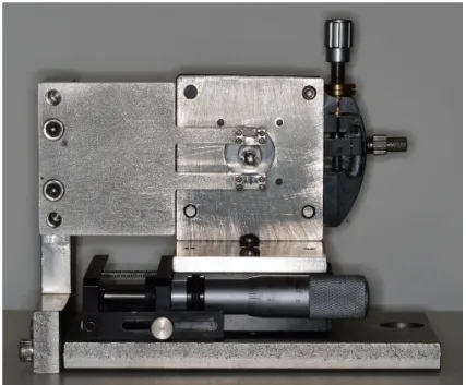
Testing Apparatus:
can be set in two distinct orientations (shown in Figures 1A-B) in order to allow manipulation in all four malocclusion simulations.
The MSA was designed to be used specifically with a mechanical testing machine (Instron® Model 4411, Instron® Corp., Canton, Massachusetts). The Instron® machine pulls a mounted archwire at a constant velocity regardless of the force required. The force felt, as a resistance to the archwire sliding through the MSA, is continuously recorded and sent to the Testworks software where it is saved digitally. The MSA is securely mounted to the Instron® base providing a consistent orientation with every use.
Mounting the Orthodontic Bracket:
A bonding jig was fabricated to allow for consistent and accurate orientation when bonding the orthodontic bracket onto a separate mounting plate. For adequate bond strength, each mounting plate was prepared by macro-abrading with a sand blaster, cleansed with alcohol, and a light coat of orthodontic dental adhesive (Orthosolo) was applied. The bracket was then placed on the mounting plate with the jig providing a consistent height and orientation between bracket and steel plate. The composite was light cured. The mounting plate with bonded bracket was then securely screwed to the MSA.
Measuring Resistance to Sliding:
tie. The desired offset or rotation was then applied to the mounted bracket. Once positioned, the Instron® was manipulated to assure no residual force existed between the archwire segment and the Instron®, and the output was balanced to zero. The Instron® was then activated to pull the archwire at a constant velocity of 10mm/min. The force required to pull the archwire was continuously measured and the results were digitally stored.
Resistance to Sliding (RS) was calculated as the linear average of force measured 1mm to 10mm of archwire displacement. The first millimeter of data was not utilized in the average, due to a plastic response observed in trials with larger deflections. This removed the area of rapidly increasing RS and focused the average on the horizontal section of the response curve.
Four separate individual tooth malpositions were simulated:
1) In-outs were tested by displacing the bracket in the buccal-lingual dimension (Figure 4A).
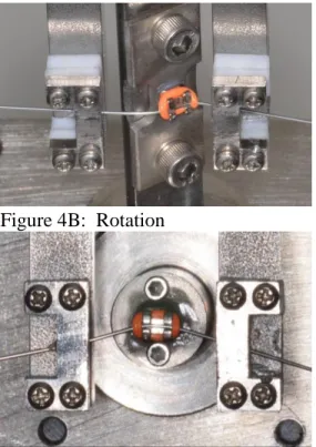
2) Rotations were tested by simulating rotation around the long axis of the tooth (Figure 4B). The center of rotation was simulated to approximately represent the center of rotation of an average sized premolar.
3) Tip was tested by rotating the bracket within the plane of the bracket face (Figure 4C). This means the bracket slot drops gingival to the line of a straight archwire on one side and rises incisal on the opposite side.
4) Vertical Steps were tested by displacing the bracket in the incisal-gingival dimension (Figure 4D).
critical change in the trend in RS was expected. The final four increments were at larger steps to provide a wide range of testing and help identify if any other critical changes in the RS trend existed. In the first six increments the same bracket was utilized; however, for the final four increments a new bracket was placed each time. The purpose for changing the bracket in each of the final four increments was due to the increased possibility that such large deflection may produce microscopic damage to the bracket and distort the results. The archwire was changed for every trial regardless of deflection size.
In-Out trials were only run on a buccally displaced bracket as this produces friction between the archwire and the base of the bracket slot. It is expected that a lingually displaced bracket would only produce friction between the archwire and an elastomeric tie, which is outside the scope of this study. 1/3mm increments were utilized from 0mm to 2mm, and 1mm increments were utilized from 2mm to 5mm. The other three orientations were also tested for a positive range. Negative increments would simply produce a mirrored yet geometrically identical scenario. Rotations were tested with 2° increments from 0° to 10°, followed by tests at 15°, 20°, 30°, and 50°. Tip was measured in 1° increments from 0° to 5°, followed by tests at 10°, 15°, 20°, and 30°. Vertical steps were measured with 1/3mm increments from 0mm to 2mm and 1mm increments from 2mm to 5mm.
For each type of malposition, five trials were run at each prescribed displacement. A one way ANOVA was used to assess whether the average values differed among the displacements. Level of significance was set at 0.05. The five RS values at each displacement were then
Results
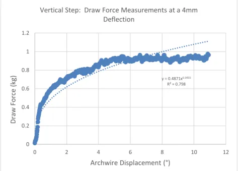
The two types of time dependent frictional responses to pulling an archwire through a simulated malocclusion are shown in Figure 5. Figure 5A shows a traditional step function as would be expected by a Newtonian friction response. Once the Instron® begins pulling the archwire, an instantaneous step up in draw force is observed and held constant throughout. In Figure 5B a different response is shown. This response was observed during larger increments of deflection and is present for all geometric malalignments. The draw force has an immediate rise, however, instead of remaining constant, it continues to rise at a decaying rate. Power regressions were utilized to develop fit lines.
In-Out (Figure 6A)
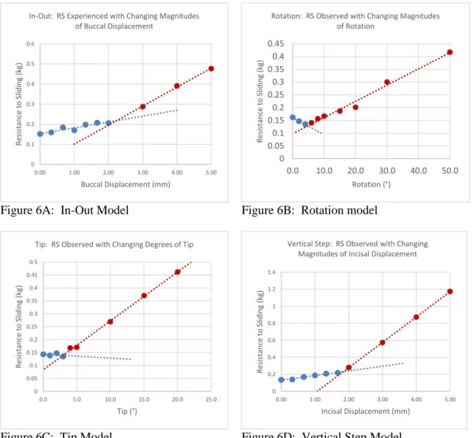
The RS increased in a linear fashion with a slight positive slope up through 2mm of buccal displacement. After 2mm of buccal displacement the RS continues to rise in a linear trend, however, the slope becomes significantly higher. The piecewise linear regression analysis provided a theoretical point, dc, at which the slope begins its sudden increase after 2.23mm (95% CI = [1.44mm – 3.02mm]). Data was collected up through 5mm of buccal displacement and no further changes in the rate of draw force increase were observed. One-way ANOVA shows a significant difference across the range of displacements (p<0.01), and the piecewise regression indicates where this significant difference occurs.
Rotation (Figure 6B)
shows a significant difference across the range of angulations (p<0.01), and the piecewise regression indicates where this significant difference occurs.
Tip (Figure 6C)
RS showed very little change from 0 to 3° of tip. From 4° on, a steady linear rise in RS was observed with increasing tip. Extrapolation of the two linear relations observed provide a theoretical θc at about 2.58°. However, a wider 95% CI (-0.76° – 5.93°) that covers 0 implicitly indicated it is possible that there is no transition point. One-way ANOVA shows a significant difference across the range of angulations (p<0.01), and the piecewise regression indicates where this significant difference occurs.
Vertical Steps (Figure 6D)
The drawing force observed when a bracket was vertically displaced steadily rose from 0 to 1.67mm displacement. A significantly greater slope was observed for displacements 2 to 5mm. The slope was unchanging from 2 to 5mm. The piecewise linear regressions appears to provide a theoretical dc at about 1.88mm (95% CI = [1.66mm – 2.11mm]). One-way ANOVA shows a significant difference across the range of displacements (p<0.01), and the piecewise regression indicates where this significant difference occurs.
Similarities existed among all configurations tested. All simulated scenarios produced an initial (no deflections or rotations present) drawing force of around 150g. This was the expected result as all scenarios, regardless of configuration, should represent no malocclusion and
Discussion
When observing the resistance to sliding, the magnitude of an archwire’s deflection is related to the time-dependent friction response. With larger wire deflections the response moves from a tradition step function to power regression response. Power regressions are most
commonly observed in plastic deformation models19, therefore, it appears that a plastic-like non-linear behavior is occurring at higher magnitudes of deflection. This change was not reported in previous testing using stainless steel and TMA wires.8,10,20 The change from a linear to a power response coincides with the critical values obtained in our malocclusion scenarios, which further implies that change may be attributed to some form of physical alteration in the CuNiTi archwire at high magnitudes of deflection. This hypothesis remains to be tested in the future.
Each malocclusion scenario appeared to show two distinct regions of how RS responds to malposition severity. Some type of change appears to occur in the friction response between these two regions. This indicates some physical change must be occurring between the bracket-wire interface, such as a physical deformation to the archbracket-wire, that ultimately increases force needed to overcome static friction. For this reason we will consider the first region “classical friction” as it would seem no physical deformations are experienced by the archwire. At the point where the response changes into a much more significant draw force experienced, it seems likely that a form of physical deformation is occurring producing “elastic binding”. Elastic binding implies that some form of non-permanent deformation is occurring to the archwire and resulting in a new form of mechanical interference to sliding.
bracket-wire alignment. Due to the archbracket-wire being a smaller dimension than the bracket slot (0.016” archwire in a 0.022” bracket slot) there is a small amount of free space in which a few degrees tip of the bracket will result in no actual contact with the tie-wings and therefore no deformation of the wire (Figure 7a). This concept was analyzed in detail in Kusy et al.’s article on resistance to sliding in the second stage of orthodontic treatment.13 This area, before the tie-wings are contacted, would only be affected by the frictional forces imposed by the base of the bracket slot and the elastic tie holding down the archwire. Because no deflection is actually being imposed on the archwire, the normal force is unchanged, and therefore, the RS also remains unchanged throughout the classical friction region. Once the archwire contacts the tie-wings (Figure 7b), a linear increase in RS is expected as tip increases. At θc, a large enough deflection is produced in the archwire by these contacts and elastic binding is observed (Figure 7c). The difference
between Figure 7b and Figure 7c was indistinguishable in our data, therefore elastic binding occurs almost immediately after the archwire contacts the tie-wings in a Tip scenario. It should be noted that the confidence interval for θc encompasses 0°, therefore, it is possible no critical angle exists within the data set. θc determined by our data, however, is consistent with previous literature,2,10,11 so it is likely the point is accurate but a larger sample size is necessary for statistical significance.
shift to elastic deformation occurs, producing the significantly increased RS response of the elastic binding region.
Rotation starts with the archwire fully seated against the slot base before any orientation changes are made to the bracket. As soon as the rotation begins, one point of contact is formed at the side of the slot that is moving buccally, however, the archwire lifts away from the side that is moving lingually (Figure 7e). As this rotation continues the wire actually makes less overall contact with the slot base, which could account for the initial drop in resistance to sliding. After reaching about 5°, the distinct change from classical friction to elastic binding occurs, and a greater sloped linear RS response continues from there.
While vertical step immediately appears to show a positively sloped RS response, one would theoretically expect to observe no change in the normal force from 0-0.15mm, as some slop should exist in the inciso-gingival dimension of the slot (similar to the Tip scenario). Due to the resolution used being larger than 0.15mm, such a region could not be observed in this data. The archwire is immediately in contact with the gingival halves of both tie wings (Figure 7f) and once a significant enough deflection occurs, contacts on all four slot walls are observed (Figure 7g). This geometric phenomenon could affect the magnitude of dc, however, evaluation of this requires further testing. A clear shift to the elastic binding region occurs at 1.85mm of
displacement. A steady linear RS response is present for the remainder of the displacement values.
increasing could provide clinical direction in choosing appropriate archwires for specific malocclusion scenario.
RS may provide uncrowding (lateral) force, similar to a push coil effect, along the archwire in aligning and leveling. Our data show that small rotation (less than 12 degrees)
produce the lowest RS of the four factors. This would imply that small rotations may be the most difficult to correct. Clinically, the completion of de-rotation has been an important criterion to determine the end point of Stage 1 treatment. Using a steel ligature tie has been routinely applied to facilitate de-rotation. It is possible, the steel ligature tie increases the deformation of and normal force on the archwire, as well as raises RS for uncrowding. However, this effect may only occur on CuNiTi wire; whether this phenomena is applicable to all shape memory alloys requires additional tests.
Conclusions
1) A critical point of deflection exists for all malocclusion scenarios where the resistance of an archwire to slide through a bracket increases significantly.
2) The critical points were observed as follows: a. In-Out: θc = 2.23mm
b. Tip: θc = 2.58° c. Rotation: θc = 4.83°
d. Vertical Step: θc = 1.88mm
REFERENCES
1. Proffit, William, ed. Contemporary Orthodontics. 5th ed. Elsevier, 2013. Print. 2. Scott, P., et al. "Alignment Efficiency of Damon3 Self-Ligating and Conventional
Orthodontic Bracket Systems: A Randomized Clinical Trial." American Journal of Orthodontic Dentofacial Orthopedics 134 (2008): 470.e1,470.e8. Print.
3. Tidy, D. C. "Frictional Forces in Fixed Appliances." American Journal of Orthodontic Dentofacial Orthopedics 96 (1989): 249-54. Print.
4. Damon, D. H. "The Damon Low-Friction Bracket: A Biologically Compatible Straight-Wire System." Journal of Clinical Orthodontics 32 (1998): 670-80. Print.
5. Kusy, Robert P., et al. "Surface Roughness of Orthodontic Archwires Via Laser Spectroscopy." The Angle Orthodontist (1988): 35-45. Print.
6. Kusy, Robert P., and John Q. Whitley. "Effects of Surface Roughness on the Coefficients of Friction in Model Orhtodontic Systems." Journal of Biomechanics 23.9 (1990): 913-25. Print.
7. Prososki, Robert R., Michael D. Bagby, and Leslie C. Erickson. "Static Frictional Force and Surface Roughness of Nickel-Titanium Arch Wires." American Journal of
Orthodontic Dentofacial Orthopedics 100 (1991): 341-8. Print.
8. Kusy, Robert P., and John Q. Whitley. "Friction between Different Wire-Bracket Configurations and Materials." Seminars in Orthodontics 3 (1997): 166-77. Print. 9. Kapila, Sunil, et al. "Evaluation of Friction between Edgewise Stainless Steel Brackets
and Orhtodontic Wires of Four Alloys." American Journal of Orthodontics 98 (1990): 117-26. Print.
10. Kusy, Robert P., and John Q. Whitley. "Resistance to Sliding of Orthodontic Appliances in the Dry and Wet States: Influence of Archwire Alloy, Interbracket Distance, and Bracket Engagement." Journal of Biomedical Materials Research 52 (2000): 797-811. Print.
11. Andreasen, George F., and Fernando R. Quevedo. "Evaluation of Friction Forces in the 0.022x0.028 Edgewise Bracket in Vitro." Journal of Biomechanics.3 (1970): 151-60. Print.
13. Kusy, Robert P., and John Q. Whitley. "Influence of Archwire and Bracket Dimensions on Sliding Mechanics: Derivations and Determinations of the Critical Contact Angles for Binding." European Journal of Orthodontics 21 (1999): 199-208. Print.
14. Thorstenson, Glenys A., and Robert P. Kusy. "Comparison of Resistance to Sliding between Different Self-Ligating Brackets with Second-Order Angulation in the Dry and Saliva States." American Journal of Orthodontic Dentofacial Orthopedics 121 (2002): 472-82. Print.
15. Matarese, Giovanni, et al. "Evaluation Fo Frictional Forces during Dental Alignment: An Experiment Model with 3 Nonleveled Brackets." American Journal of Orthodontic Dentofacial Orthopedics 133 (2008): 708-15. Print.
16. Miles, Peter G. "SmartClip Versus Conventional Twin Brackets for Initial Alignment: Is there a Difference?" Aust Orthod J 21 (2005): 123-7. Print.
17. Miles, Peter G., Robert J. Weyant, and Luis Rustveld. "A Clinical Trial of Damon 2 Vs Conventional Twin Brackets during Initial Alignment." The Angle Orthodontist 76 (2006): 480-5. Print.
18. Muggeo, V. M. R. "Estimating Regression Models with Unknown Break Points." Statistics in Medicine 22 (2003): 3055-71. Print.
19. Bellemare, S., M. Dao, and S. Suresh. "The Frictional Sliding Response of Elasto-Plastic Materials in Contact with a Conical Indenter." International Journal of Solids and Structures 44 (2007): 1970-89. Print.
APPENDIX
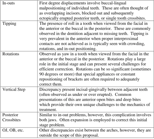
Table 1: Factors limiting Stage I movement
In-outs First degree displacements involve buccal-lingual
malpositioning of individual teeth. These are often thought of as overlapping incisors, blocked out and subsequently
ectopically erupted posterior teeth, or single tooth crossbites. Tipping The presence of roll in a tooth when viewed from the facial in the anterior or the buccal in the posterior. These are commonly observed in the dentition adjacent to missing teeth. Tipping is very prevalent in the anterior when proper interproximal contacts are not achieved as is typically seen with crowding, rotations, and in-out positioning.
Rotations Observed as yaw in a tooth when viewed from the facial in the anterior or the buccal in the posterior. Rotations play a large role in the initial stage and can present several challenges for efficient correction. Rotations can be so significant (sometimes 90 degrees or more) that special appliances or constant
repositioning of brackets are often required to adequately correct them.
Vertical Step Discrepancy present incisal-gingivally between adjacent teeth (often observed as under or over erupted). Common
presentations of this are anterior open bites and deep bites which provide their own unique challenges to the mechanics of treatment.
Posterior Crossbites
Similar to in-out problems, however, this complication involves both jaws. Often expansion is employed to correct this initial stage problem.
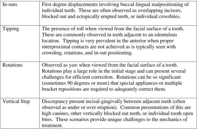
Table 2: Specific malalignments defined
In-outs First degree displacements involving buccal-lingual malpositioning of individual teeth. These are often observed as overlapping incisors, blocked out and ectopically erupted teeth, or individual crossbites. Tipping The presence of roll when viewed from the facial surface of a tooth.
These are commonly observed in teeth adjacent to an edentulous location. Tipping is very prevalent in the anterior when proper interproximal contacts are not achieved as is typically seen with crowding, rotations, and in-out positioning.
Rotations Observed as yaw when viewed from the facial surface of a tooth. Rotations play a large role in the initial stage and can present several challenges for efficient correction. Rotations can be so significant (sometimes 90 degrees or more) that special appliances or multiple bracket repositions are required to adequately correct them.
Figure 1: Illustrated examples of factors limiting stage I treatment.
In-Out Rotation
Tipping Vertical Step
Figure 3: The MSA
Figure 3A: MSA Orientation for Tip & Vertical Step
Figure 4: The four simulated malalignment scenarios
Figure 4A: In-Out Figure 4B: Rotation
Figure 5: Different response curves observed
Figure 5A: All data points from a single Vertical Step test at a 1mm displacement. The step function response is observed as expected. A sharp rise in draw force is noted as tension is built up in the archwire before the resultant frictional force (about 0.2kg in this scenario) is overcome and sliding begins.
Figure 5B: All data points from a 4mm deflection Vertical Step test. There is a distinct curvature in the rise towards a maximum load. Similar results were observed in Vertical step trials beginning at about 2-3mm displacement.
0 0.05 0.1 0.15 0.2 0.25
0 2 4 6 8 10 12
Draw
Force (kg)
Archwire Displacement (mm)
Vertical Step Draw Force Measurements at 1mm Deflection
y = 0.4871x0.3455
R² = 0.798
0 0.2 0.4 0.6 0.8 1 1.2
0 2 4 6 8 10 12
Draw
Force (kg)
Archwire Displacement (°)
Figure 6: Linear trends observed for each malalignment scenario
Figure 6A: In-Out Model Figure 6B: Rotation model
Figure 6C: Tip Model Figure 6D: Vertical Step Model 0 0.1 0.2 0.3 0.4 0.5 0.6
0.00 1.00 2.00 3.00 4.00 5.00
R esi st an ce t o Sl idi ng ( kg )
Buccal Displacement (mm) In-Out: RS Experienced with Changing Magnitudes
of Buccal Displacement
0 0.05 0.1 0.15 0.2 0.25 0.3 0.35 0.4 0.45
0.0 10.0 20.0 30.0 40.0 50.0
R esi st an ce t o Sl idi ng ( kg ) Rotation (°)
Rotation: RS Observed with Changing Magnitudes of Rotation 0 0.05 0.1 0.15 0.2 0.25 0.3 0.35 0.4 0.45 0.5
0.0 5.0 10.0 15.0 20.0 25.0
R esi st an ce t o Sl idi ng ( kg ) Tip (°)
Tip: RS Observed with Changing Degrees of Tip
0 0.2 0.4 0.6 0.8 1 1.2 1.4
0.00 1.00 2.00 3.00 4.00 5.00
R esi st an ce t o Sl idi ng ( kg )
Incisal Displacement (mm) Vertical Step: RS Observed with Changing
Figure 7: Graphical representations of archwire deflection patterns for each scenario
Figure 7a: Diagrammatic representation of “Classical Friction” orientation in Tipping.
Figure 7b: A small amount of tip is possible before the archwire makes its first contacts with the bracket slot, as shown in this diagram.
Figure 7c: Once the tip becomes significant enough, “Elastic Binding” occurs and RS begins to increase significantly.
Figure 7d: Diagrammatic representation of the archwire contacts present in the In-Out orientation.
Figure 7e: Diagrammatic representation of the archwire contacts present in the Rotation orientation.
Figure 7f: Diagrammatic representation of the archwire contacts present in the Vertical Step orientation.