AKNOWLEDGEMENTS
I would like to thank Dr. Linda Little for her support and guidance during my tenure at that Governor's Waste
Management Board. Also I would like to thank Dr. Steve
Simon for his editorial suggestions and Dr. James Watson for
his comments during this project.
Special gratitude is expressed to my wife and daughter
for their total support and tolerance.
In closing I would like to thank Cliff Collins, George
Abernathy Canada, Don Eligman, and Jim Massey for providing
ANDREW MORROW BARRON, Geologic and Hydrologic
Characteristics of Existing Low-Level Radioactive Waste
Disposal Sites in the Eastern United States - Implications
for North Carolina
The geologic and hydrologic characteristics of low-level radioactive waste (LLRW) disposal sites in the eastern United States are reviewed in this technical report. Since
J North Carolina has been designated as the next host for a
CHAPTER 1. CHAPTER 2. CHAPTER 3. CHAPTER 4. CHAPTER 5. CHAPTER 6, CHAPTER 7
TABLE OF CONTENTS
Page
Introduction ... 1
Maxey Flats, Kentucky... 11
Site History... 12
Geologic Characteristics ... 13
Hydrologic Characteristics ... 17
Problems Encountered ... 23
West Valley, New York... 26
Site History... 26
Geologic Characteristics ... 28
Hydrologic Characteristics ... 35
Problems Encountered ... 38
Sheffield, Illinois ... 43
Site History ... 43
Geologic Characteristics ... 45
Hydrologic Characteristics ... 51
Problems Encountered ... 55
Barnwell, South Carolina ... 58
Site History ... 58
Geologic Characteristics ... 60
Hydrologic Characteristics ... 63
Problems Encountered ... 69
General Geology and Hydrology of North Carolina ... 72
Blue Ridge ... 72
Piedmont ... 78
Coastal Plain ... 79
Engineered Barriers ... 82
Properties of Concrete ... 85
Concrete Aggregates ... 86
Portland Cement Types ... 86
Concrete Composition ... 90
Hydraulic Properties ... 90
Page
CHAPTER 8. Implications for North Carolina ... 100
Possible Constraints ... 101
Summary ... 105
LIST OP FIGURES
Figure Page
1. Location of Maxey Flats
disposal site ... 12
2. Diagrammatic cross-section of the
Maxey Flats site ... 15 3. Streams, topography, and site
boundary... 18
4. Diagrammatic hydrologic section of
the Maxey Flats site ... 22
5. Location of the West Valley site... 27
6. Geologic cross-section at West
Valley ... 31
7. Location of cross-section, streams,
and topography ... 32 8. Idealized ground-water flow at West
Valley ... 39
9. Location of the Sheffield disposal
site... 44
10. Geologic cross-section of the
Sheffield site ... 47
11. Location of geologic cross-sections ... 48
12. Possible ground water flow through
the unsaturated zone ... 56
13. Location of the Barnwell LLRW
disposal site ... 59
14. Stratigraphy and lithology of the
Barnwell LLRW site ... 61
15. Geologic cross-section showing the
ground-water system at Barnwell ... 65
16. Physiographic provinces of North
Carolina, also shown are geologic
belts and faults ... 73
17. Ground-water situation in the Blue
18. Water levels at three long-term
wells during the 1987 water year... 77
19. Generalized occurrence of ground
water in the Coastal Plain, sequence of rocks and beds are
diagrammatic ... 81
20. Diagram of the reinforced concrete
LIST OF TABLES
Table Page
1. Typical radionuclides in LLRW by
generators ... 2
2. Stratigraphy of the sediments at
the West Valley site ... 30 3. Summary statistics for wells in
the Blue Ridge, Piedmont, and
Coastal Plain ... 76 4. Performance objectives of LLRW
disposal facilities and disposal
system functions ... 83
5. Different types of Portland Cement,
IKTRODUCTION
The disposal of low-level radioactive waste (LLRW) in
the United States has evolved over the years in response to commercial use of radioactive materials. LLRW is defined in
Title 10, Code of Federal Regulations Part 61 (10 CFR Part
61), as all radioactive waste that is not classified as
high-level waste, transuranic waste, spent nuclear fuel, or uranium or thorium mine tailings. Since LLRW is defined by exclusion, a small fraction of LLRW can contain fairly high
concentrations of radionuclides.
Low-Level Radioactive Waste encompasses a broad range of wastes. Any industry, hospital, medical, educational or
research institution, private or government laboratory, or
facility involved in the nuclear fuel cycle, that utilizes
radioactive materials generates LLRW. Due to the diversity
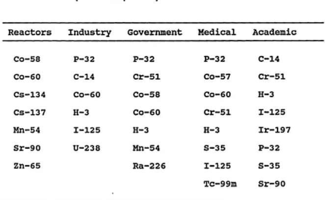
of generating facilities, LLRW is produced in many physical forms and volumes. Table 1. lists radionuclides typically
found in LLRW from several types of generating facilities. Specific activities of LLRW can vary from fractions of millicuries per cubic foot (e.g., laboratory wipes) to hundreds of curies per cubic foot (e.g., sealed sources).
The Nuclear Regulatory Commission (NRC) defines LLRW
TABLE 1. Typical radionuclides in LLRW, by generators
(from Lee, 1986).
Reactors Industry Government Medical Academic
Co-58 P-32 P-32 P-32 C-14
Co-60 C-14 Cr-51 Co-57 Cr-51
Cs-134 Co-60 Co-58 Co-60 H-3
Cs-137 H-3 co-60 Cr-51 1-125
Mn-54 1-125 H-3 H-3 Ir-197
Sr-90 U-238 Mn-54 S-35 p-32
Zn-65 Ra-226 1-125
Tc-99m
S-35
as set forth in 10 CFR 61.55 of the NRC regulation. Class
A, B, and C wastes are generally suitable for near-surface
disposal. Waste that exceeds the Class C limit on
radionuclide concentrations is not considered suitable for
near-surface disposal and was made the responsibility of the
federal government by the Low-Level Radioactive Waste Policy
Amendments Act of 1985. In general the human toxicity increases from Class A to Class C wastes and this increase
is reflected in the more stringent disposal requirements.
Initially commercial LLRW was deposited at off-shore
disposal sites approved by the U.S. Atomic Energy Commission (AEC). In response to economic factors and problems
associated with monitoring ocean disposal, the AEC
determined that land disposal of LLRW was a more practical method. In 1960, two interim disposal sites were designated and began accepting both federal and commercial LLRW. In 1962, the first commercial LLRW disposal facility opened at
Beatty, Nevada; later in that same year the Maxey Flats,
Kentucky disposal site began operation. Eventually other sites were located at West Valley, New York, Hanford,
Washington, Sheffield, Illinois, and Barnwell, South Carolina. All six commercial LLRW disposal facilities
employed shallow land burial technology. In this technology,
waste containers are placed in an excavated trench which is
with infiltration of precipitation, leachate accumulation,
and radionuclide migration (primarily tritium), three sites
have been closed, though the disposal sites at Beatty,
Barnwell, and Hanford have continued to accept waste.
Growth in the volume of LLRW and the projected closings
of licensed disposal sites have required the development of
additional capacity. In 1980, Congress passed the Low-Level
Radioactive Waste Policy Act, which established a new
framework for LLRW management. The Act placed the
responsibility for LLRW disposal on every state, but
recommended the use of regional disposal facilities as the
most appropriate means for resolving the problem. As a
result, most states have formed regional compacts and many
are involved in the process of siting a LLRW disposal
facility. The Southeast Compact includes Alabama, Georgia,
Florida, Mississippi, North Carolina, South Carolina,
Tennessee, and Virginia. On September 11, 1986, the
Southeast Compact Commission designated North Carolina as
the first host state to replace Barnwell and ruled that they
must provide a LLRW disposal facility by December 31, 1992.
North Carolina has accepted its host state status;
however, in light of the performance history of the six
existing LLRW disposal facilities. North Carolina has
enacted legislation which affects the type of disposal
technology ultimately chosen. In 1987 North Carolina
enacted legislation that prohibits shallow land burial,
seasonal high water table. These engineered barriers will
be designed to complement or improve the performance of a
disposal site but are not intended to substitute or compensate for a site deficiency.
Some widely considered alternative methods for near surface disposal include: below-ground vaults, above-ground
vaults, earth-mounded concrete bunkers, augered holes, and
mined cavities. The technology selected by North Carolina
could be any one of these alternatives or a combination of different technologies. These alternatives cover a wide-range of disposal technologies and have been discussed by
many authors (Baird et al.. 1986; National Low-Level Waste
Management Program, 1987; Illinois Department of Nuclear
Safety, 1987) in detail. A general description of these
disposal alternatives follows:
o Above-Ground Vaults - This disposal technology consists of placing LLRW containers in engineered
concrete structures located above the ground
surface. This method does not employ an earthen
cover but relies on the structure to isolate the
LLRW from the biosphere. The material used to
construct this facility would likely be reinforced concrete, however, due to the lack of long-term
experience with modern concrete it is difficult to
known that degradation mechanisms exist in the
environment which could lead to structural
failure. It should be noted that some
modifications of this technology involve an
earthen cover. This design would be described as
being above-grade but below-ground.
Below-Ground Vaults - This technology places the LLRW in engineered concrete structures located below the natural surface grade. The below-ground vault is covered with an earthen cover similar to
covers used in shallow land burial. The structure
consists of reinforced concrete floors, walls, and roof. The incorporation of a below-ground vault
and an earthen cover restricts water infiltration, prevents human or biological intrusion, and
reduces exposure rates from gamma radiation at the
land surface.
o Earth-Mounded Concrete Bunker (EMCB) - This
disposal technology has been used for France.
This method incorporates both above-ground
disposal of LLRW (Class A waste) within an earth
covered tumulus and below-ground disposal of waste (Class B and C) in a concrete bunker. At the
reinforced concrete in the construction of floors,
walls, and roof. The tumulus and cover are
constructed of earthen materials. As a hybrid
technology involving the integration of trench
disposal, vaults, and complex waste packaging, the
EMCB is a relatively complex option to implement.
o Modular Concrete Canister Disposal (MCCD) - The
disposal of LLRW by this method involves placing
individual waste containers in modular concrete
canisters which, in turn, are placed below the
natural grade of the site. With the exception of
the use of concrete canisters, this disposal
method resembles shallow land burial and
below-ground vault disposal (the concrete canisters provide structural stability). By using both earthen cover and concrete canisters, the
isolation of radionuclides from the environment is
enhanced.
o Augered Holes (Shaft Disposal) - Augered holes or
shaft disposal involves the disposal of
radioactive waste in shafts or boreholes that are
drilled, bored, or augered by conventional
methods. These shafts may be unlined or lined
reduce water infiltration into the disposal unit
and improve the structural integrity. Below
grade, the upper ten feet of the shaft is sealed
with an engineered barrier and the whole unit is
covered with a 5 to 10 ft thick engineered
barrier.
o Mined Cavities - Mined cavities have been
suggested for the disposal of LLRW in the United
States and are currently a disposal method used in
West Germany. This technology could use an
already existing mine or one specially
constructed. Mined cavities can be located in
salt, coal, granite, or limestone beds. Although
mined cavities would not have the surface
degradation problems associated with other
disposal methods, the reguirements stated in
10CFR61 are not satisfied by this method and,
therefore it could not be licensed for use in the
U.S.
Although these alternative methods briefly summarized
above are workable and currently licensable under 10 CFR
Part 61 (except mined cavities), the NRC has focused its
resources on buried placement technologies and on disposal
techniques that incorporate cementitious materials (Baird et
based on the knowledge that an engineered LLRW facility is
required to perform on the order of 300 to 500 years. Such a structure will most probably be constructed of Portland
cement-type concrete (Baird et al.. 1986; Pittiglio and
Tokar, 1987; National Low-Level Waste Management Program, 1983). Although Portland cement has been in use only 150
years, cement specialists in general agree that the
long-term durability of concrete requires additional protection from acid-rain, freeze/thaw cycles, and erosional processes.
An earthen cover would provide protection from environmental
degradation and also provide an additional barrier to radionuclide release and intruder protection. The NRC already has substantial experience with earth-covered
structures and this knowledge could be used in developing an
effective disposal technology. This report focuses on the
degradation mechanisms that effect concrete engineered barriers.
Since engineered barriers cannot substitute or
compensate for a site deficiency, geological and
geohydrological characteristics remain critical factors in
preventing the migration of radionuclides through the groundwater. In this technical report the geology and
geohydrology of LLRW facilities in the eastern United States will be reviewed. The disposal sites are located at
Barnwell, South Carolina; Maxey Flats, Kentucky; Sheffield,
10
radionuclide migration will be discussed. Since
environmental conditions exist that promote barrier failure, this report will examine the degradation mechanisms of
concrete engineered barriers. Based on this information, the general geology/hydrology of North Carolina, and
constraints enacted by North Carolina's legislation, this
report will identify possible geologic and geohydrologic conditions in North Carolina that are not suitable for
VIAXEY FLATS, KENTUCKY
Site History
Maxey Flats was opened as a LLRW disposal facility in
January 1963 under agreement between Kentucky and Nuclear
Engineering Co. (now U.S. Ecology, Inc.). The burial site, which consists of 102 ha (252 acres), is located on a flat top ridge in rural Fleming County, 109 km northwest of
Lexington, Kentucky (Fig. 1). The site was operated until
problems with radioactive waste migration and leachate accumulation within the burial trenches forced facility
closure in December 1977. Maxey Flats is currently in
shutdown status, with the required maintenance, monitoring, and evaporation of leachate from burial trenches being
performed by Hittman Nuclear Development Corporation.
The burial site consists of 46 closed trenches, one open trench, a number of hot wells, and several special pits.
The trenches are generally unlined and vary considerably in size from 46 to 207 m (150 to 680 ft) in length, 3 to 22 m
(10 to 75 ft) in width, and 2.7 to 9 m (9 to 30 ft) in depth
(Clancy et al.. 1981). The trench floor slopes one degree
toward a sump constructed at the low end for dewatering purposes. The trenches have been backfilled with a minimum
12 STUDY AREA
KENTUCKY
\ \ "
-M-(m) \_^
\ @
)^Hillsboro
V^ V,^^ Maxey
^^r^
\ ^^ «;''^^rC^ ^\'^^s
/^^^^ 1
/
Ringo^^ \.
^ Mills ^^O^X
Sharkey \ /
1 /
—•—' ''\^^_^^,^-^^'^ Farmers
/Morehcad
0
h-10 MILES
_____I
10 15 KILOMETERS
V64;
EXPLANATION
Interstate Highway
Federal Highway
State Highway
FIGURE 1. Location of Maxey Flats disposal site
2 mR/hr at the trench surface is not exceeded. When a trench
was filled with waste, a minimum of 1 m (3.3 ft) of clayey soil was backfilled and compacted in layers. To assist in
water runoff, a mounded cap was constructed and shallow rooted vegetation planted to impede erosion.
Between 1963 and 1978 approximately 135,089 m-^ of waste
was disposed at Maxey Flats. This waste contains
approximately 2.4 million curies of by-product material, 431 kg of special nuclear fuel (plutonium, uranium-233, and
enriched uranium-235), and 242 x 10"^ kg (533 thousand
pounds) of source material (uranium and thorium not included
in special nuclear material). The majority of the waste was
received in solid form; however 2.2 million liters (58 thousand gallons) of liquid waste was accepted and solidified in urea-formaldehyde before burial.
Geologic Characteristics
The subsurface geology of the disposal site consists of
gently dipping sedimentary rocks of Silurian, Devonian, and
Mississippian Age. These sedimentary rocks are composed of
14
beneath the site in ascending order are: 1) the Upper Crab
Orchard (Silurian); 2) the Ohio Shale (Devonian); 3) the Bedford Shale (Devonian to Mississippian); 4) the Sunbury Shale (Mississippian); and 5) the Borden Formation
(Mississippian) composed the Henly Bed of the Farmers
Member, the Farmers Member, and the Nancy Member. A
diagrammatic cross-section of the Maxey Flats site is shown
in Figure 2.
The Crab Orchard is predominantly a clayey shale mostly greenish gray to gray. This shale does not have a high
fracture density and is relatively impermeable. The Crab Orchard is assumed to be the lower hydraulic boundary, with all groundwater flowing to the side of the hill and
eventually discharging into the stream system.
The Ohio Shale averages approximately 56 m (184 ft)
beneath the Maxey Flats site and is a dark-gray to black, highly carbonaceous shale. The Ohio Shale forms steep slopes and is well exposed at the burial site.
Greenish-gray shale beds up to 3 m (10 ft) thick occur 15 m to 18 m (50 to 60 ft) below the top of this unit.
The Bedford Shale is approximately 8 m (25 ft) thick at the burial site and occurs as a greenish gray to
light-olive-gray silty shale. The Bedford Shale has poor
fissility (property of splitting easily along closely spaced
parallel planes) and weathers to irregularly shaped chips. Locally thin sandstone lenses occur several feet above the
EXPLANATION
s
o
I
m cu
100
200
X 3 00
U4
Q
400
-Typical burial trench __.
Nancy Member
Farmers Member
and basal Henley Bed _
Sun bury Shale
.Bedford Shale
Shale Sandstone
Colluvium and alluvium
Borden Formation
Colluvium and soil
Ohio Shale
Upper part of
Crab Orchard
Formation
Alluvium
VERTICAL EXAGGERATION APPROXIMATELY X 4
FIGURE 2. Diagrammatic cross-section of the Maxey Flats
16
The Sunbury Shale is approximately 5 m (18 ft) thick at the burial site and is a dark gray to black carbonate rich
rock. This unit is highly fissile and forms steep slopes.
The Borden Formation is composed of the Henly Bed of
the Farmer Member, the Farmer Member, and the Nancy Member.
The Henly Bed at disposal site is approximately 2 m (6 ft)
thick and is greenish shale. The Henly Bed commonly
contains a few sandstone lenses .3 to .6 m (1 to 2 ft)
thick in its upper section. The Farmer Member is sandstone
unit with interbedded shale and is approximately 11 m (36
ft) thick at the site. The sandstone is very-fined grain
and occurs in tabular beds up to 1.2 m (4 ft) thick. The
interbedded shales are mostly greenish gray and occur in
lenses less than .91 m (3 ft) thick. The Nancy Member is
predominantly a shale with two distinct marker sandstone
beds at the Maxey Flats site. This unit is approximately
14 m (45 ft) thick. The shale is blue to greenish gray and
poorly fissle. The marker sandstone lenses are
yellowish-brown and occur as two beds up to .6m (2 ft), near the base
of the Nancy Member (McDowell et al.. 1971).
Although the rocks in this region are not presently
subjected to regional stresses, all rock units above the
Crab Orchard have characteristic fractures. These fractures
occur in sets (dips of 80 to 90°) and were generated by
unknown regional stresses. The fractures exhibit iron-oxide
1982). Since the burial trenches are located within the Nancy Member, fractures present may serve as a pathway for
radionuclide migration.
Hydrologjc Characteristics
Surface Water
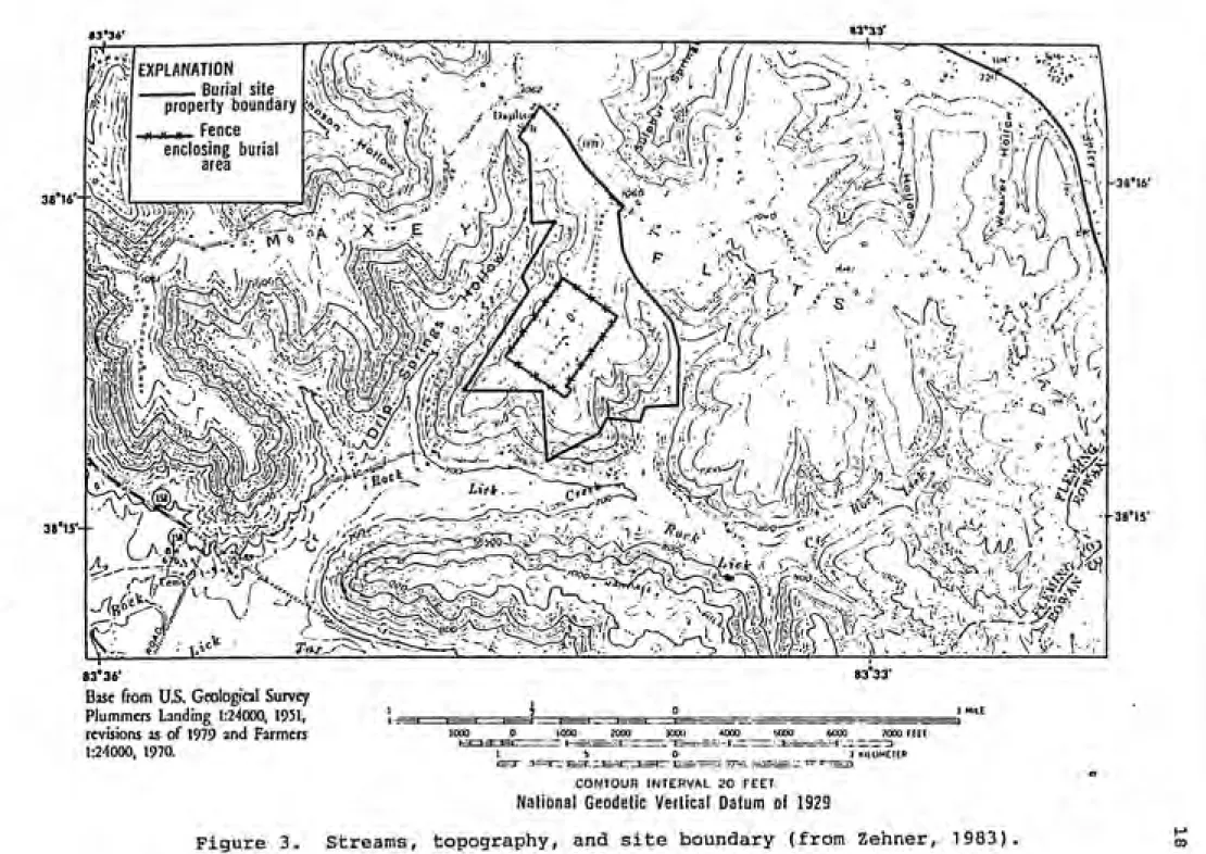
Surface water drainage from the LLRW disposal site is by Drip Springs Hollow to the west, Rock Lick Creek to the South, and the unnamed stream to the east (Fig. 3 ).
Surface flow occasionally ceases in all the streams; however pools of water are always present in low areas within the
stream bed and indicate subsurface flow. Seventy-five
percent of the surface runoff from the burial site flows
down a small valley into the unnamed stream. Drainage from
these tributaries flows into Fox Creek and then into the
Licking River (National Low-Level Radioactive Waste
Management Program, 1982).
The climate at Maxey Flats is humid continental,
characterized by warm humid summers and cold winters. Mean annual precipitation ranges from 109 to 119 cm (43 to 47 in). The driest months are late summer and autumn; the wettest months are usually during spring and summer (Clancy
et al.. 1981). Streamflow data from the United States
Geological Station at Rock Lick Creek indicates that average
38'16'--38*15'
83*33
83'34'
EXPLANATION
Burial site ; n><^
property boundary
,. .K n Fence enclosing burial
area
ͣ
y/ic
^c^
ͣ
''~%.-00
<rP'"K, "^'i
-38*16'
-38*15'
83° 36'
Base from U.S. Geological Survey
Plummers Landing 1:24000, 1951,
revisions as of 1979 and Farmers
1:24000, 1970.
83 33'
1000 0 1000 2000 3000 _4000______iooo__ 6000 7000 FEEI
1 KllUMETER -T==3"::^:e=^h:7
CONTOUR INTERVAL ?0 FfET
National Geodetic Vertical Datum of 1929
Figure 3. Streams, topography, and site boundary (from Zehner, 1983).
accounting for approximately 10 percent of the total
discharge.
Ground Water
Hydrologic contacts correspond to stratigraphic
contacts below the Farmers Member. Four hydrologic units above the Farmers member which do not correspond to the
stratigraphy are: 1) the weathered section (regolith) of the Nancy Meinber which includes the upper and lower sandstone marker beds, 2) the unweathered section of the Nancy Member,
3) the shale-sandstone sequence at the base of the Nancy
Member, and 4) the predominantly sandstone section of the
upper Farmers Member (Zehner, 1983) . ,
The stratigraphic section, which includes the regolith and bedrock above the shale-sandstone sequence at the base
of the Nancy Member, is of hydrologic importance since this
is the strata where the disposal trenches are located. The bottoms of most trenches at Maxey Flats are at the lower
sandstone bed in the Nancy Member. Water levels in most
trenches do not appear to correspond to a particular
horizon, but vary from 315 to 317 m (1033 to 1040 ft) above
sea-level. Due to the accumulation of water in the
trenches, the upper groundwater system has been altered from
its original state. The irregular water table could be due to local groundwater mounds or local depressions from
20
The uppermost water table is located at the base of the regolith in the trench area. Decreasing heads with depth may indicate perched water tables or a vertical gradient in
saturated rock. Water table levels and the corresponding rock type are as follows: 1) 304 m to 309 m (997 ft to 1014 ft) above sea-level in the Lower Nancy Formation; 2) 296 m
to 297 m (971 ft to 974 ft) above sea-level in the Lower
Farmers Member; 3) 286 m to 287 m (938 ft to 942 ft) above
sea-level in the Sunbury Shale; and 4) 230 m to 237 m (755
ft to 778 ft) in the Ohio Shale.
The ground-water system at Maxey Flats probably
consists of sequences of saturated and unsaturated zones, with more than one sequence in some hydrologic units. The
thickness of the unsaturated zones in most rocks is less
than 12 m (39 ft) thick and possibly only a few meters thick in some units. The lower sandstone bed of the Nancy Member
is saturated at the waste site and the lower shale has
variable levels of saturation. Most rocks between the lower
part of the Farmers Member and the Ohio Shale are probably saturated, with the possible exception of the upper Sunbury
Shale.
Cores taken from wells at Maxey Flats show hydraulic
conductivities that range from 10~^° to 10~^ cm/s (10~^ to
10"^ ft/d) in the sediments above the bedrock. Hydraulic
conductivity is the ability of a porous material to transmit water and depends on a variety of physical factors
secondary fractures, specific weight and the dynamic
viscosity of the fluid. The secondary conductivity due to joints and fractures has been estimated to be on the order
of 10"^ cm/s (10"^ ft/d). Due to the overall low
conductivity of rocks from this site, the primary ground water migration occurs through the secondary permeability
(fractures) in the shale units and the interlinking
sandstone beds (Clancy et al., 1981).
Ground water entering the surface at the burial site flows vertically downward through the unsaturated zones and
has vertical and horizontal flow components in the saturated zones. Flow is predominantly vertical in the unweathered
Nancy Member, Henly Bed, and Bedford Shale. Lateral flow
occurs in the lower sandstone marker bed of the Nancy
Member, the upper part of the Farmers Member, Sunbury Shale,
and Ohio Shale. A generalized flow diagram is shown in
Figure 4.
Models by Zehner (1983) indicate that 70 percent of the water entering the burial site discharges to the hillside colluvium from rocks above the lower part of the Farmers Member. Twenty percent of the flow discharges from the units between the Ohio Shale and the The upper Farmers Member. The remaining flow discharges by way of the Ohio
22
Farmers Member and lower part of the Ohio Shale are saturated. Other units
above the Ohio Shale may be saturated
(as shown by flowlines), or may be
unsaturated. Upper part of the Ohio Shale is unsaturated.
Evaporation and transpiration LU LlJ o CO
Weathered shale regolith Lower sandstone marker bed
Unweathered Nancy Member
Upper part of the
,Farmers Member
Lower part of the
Farmers Member yHenley Bed Sunbury Shale Bedford Shale Typica trenches Rainfall
m/j ji\\\^A\\\\\
www \
Colluvium and soi Drip Springs Alluv- "°"°*ium Upper part of Crab Orchard Formation
Ohio Shale
Colluvium
and soil
VERTICAL EXAGGERATION 3
Arrows below ground level represent flowlines. Length and density of flowlines do not indicate velocity or volume of flow.
Figure 4. Diagrammatic hydrogeologic section of the
Problems Encountered
In the early 1970's, Kentucky became concerned with the
accumulation of water in the completed trenches and the
increase in the volume and activity of the wastes received
for disposal. Water accumulated as result of a high rate of precipitation (112 cm/yr) coupled with the decomposition of
waste, creation of new voids, and trench cover subsidence. These conditions have lead to water migration through the cap and the accumulation of contaminated water in the
trenches known as the "bathtub effect". In 1973, Kentucky
required the site operator. Nuclear Engineering Co., to initiate a water management program. This program involves
pumping the contaminated water from trenches to above ground holding tanks, floculating and filtering, evaporating the
water (process uses a combustion evaporator), and
transferring the evaporator concentrates to a storage tank
for later disposal.
Analysis by Weiss and Columbo (1980) showed that
leachate is contaminated with a variety of radionuclides,
including: ^H ^°Co,^^Sr, ^°Sr, ^^^Cs, ^^''cs, ^^^Pn, and
^•^^Pu. Tritium concentrations were the greatest, ranging
from 1.1 X 10^ to 2.3 X 10^ pCi/L. Concentrations of
radionuclides differ between trenches and are a result of
the quantity, waste form, and type of nuclide buried.
Radionuclides have been detected in the major drainage
way on-site and in the streams off-site (Montgomery and
24
pCi/L) detected in samples from the burial site include:
Tritium (45,000 pCi/L), cobalt-60 (5 pCi/L), strontium-90
(90 pCi/L), niobium-95 (.9 pCi/L), zirconium-95 (<.6 pCi/L),
ruthenium-106 (<.4 pCi/L), and cesium-137 (.2 pCi/L).
Sample locations and concentration of dissolved
radionuclides detected outside the burial site were: unnamed
stream, tritium (13,000 pCi/L) and strontium-90 (6 pCi/L);
Drip Springs Hollow near Rock Lick Creek, tritium (4,700 pCi/L) and strontium-90 (.9 pCi/L); Rock Lick Creek below
unnamed valley, tritium (4,700 pCi/L) and strontium-90 (5.8
Ci/L); and Crane Creek, strontium-90 (2 pCi/L). Waste
radionuclides in the stream water may have moved from the
disposal site by base flow, or by overland runoff carrying
contaminates soil from the waste site (Zehner, 1983). The most significant radionuclide, based on
concentration in groundwater, has been tritium. Samples taken from the wells at Maxey Flats vary depending on the well, the location and time of year. Concentrations of
tritium vary from less than 200 pCi/L to 6.8 x 10^ pCi/L
(Zehner,1983). In addition to tritium, strontium-90 and plutonium-90 have been found in water samples; however these
radionuclides may have been introduced during drilling, well
completion, or from surface runoff from contaminated soil
and samples from most wells are of limited value in
determining the quality of ground water.
Factors contributing to radionuclide releases at Maxey
soils and poor disposal practices. These factors have resulted in the subsidence of trench covers, increased
infiltration of precipitation, accumulation of leachate. At Maxey Flats radionuclides are migrating both through the
surface water and the ground water. Due to the small base
flow in this area, the principal route for radionuclide release is through surface water runoff. Although
radionuclide releases have and continue to occur from the
Maxey Flats LLRW facility, studies performed by the NRC and other investigators conclude that there is no significant
CHAPTER 3
WEST VALLEY, NEW YORK
Site History
The West Valley LLRW facility is located at the Nuclear Service Center, 50 "km (31 miles) southeast of Buffalo, in a
rural area near West Valley, New York (Fig. 5). The Nuclear Service Center, which is owned by the New York State Energy Research and Development Authority, includes: 1) a nuclear fuel reprocessing center, 2) a spent fuel recovery and
storage facility, 3) a heavy liquid storage area, 4) a high level radioactive waste disposal facility, and 5) a LLRW disposal facility. The LLRW site, operated by Nuclear Fuel Services, was opened as a commercial facility in 1963 and accepted LLRW from the northeast and middle Atlantic states.
In 1971 water levels began rising in a few of the burial
trenches. By 1975 the water level reached the ground surface in trench 4 and broke through the cover of the
trench. This radioactive seep had a flow rate of 3.8 L/d (1 gal/d) (National Low-Level Radioactive Waste Management
Program, 1982). As a result of this leakage problem,
Nuclear Fuel Services terminated commercial operations.
Since 1975 the disposal site has been in shutdown condition
and pumping of leachate has been performed.
79°00' 7E°45' 78°30' 42°37'30"
'Lake
Erie
/
/ 1 ^Buffalo 30 km
1 WYOMING ^
"^ 1 COUNTY V
4
=\ /aERIE COUNTY
t
)
X
iX
^ "} ^^'^
^
^=5i^:«=^rArcade y1 r.' t -^
' ^\springvllle 45-18 ]cL^^ .---_\^ / , - ]
42°30'00" - ( (
37-46 J X^ Jr^T^
^—
^ 12-14
Co \ /^ 1 J
Dl \ / \\ \
Clea^-S^ \ o^
N<^\^ 06-37
Or I {• I -. ^/"" J \«=s»'^T^:^SWestern New York \\^°-^ >----s./"^^ 2
<l
Gowanda CT|
*>^ ^?N. Nuclear Service
\% >^vKV Center |0O
a V_o. f/)/CX ^'K. l>
<
r ^
10-35V=> ^<^:->\ 1 22-40°^ ^ ;<3|
fc Ashford^c. 20-331 JWest Valley
UJ
42°22'30"
-X
1
(1
.p-Hollow " OgT 20
CATTARAUGUS COUNTY
;<
\^ A
NEW /^EXPLANATION
ȋ STREAM-GAGING STATION \ /^ \ York/
iTSSffalo
Study areaV
S
WELL-Seconds of latitude AiCattaraugus ^~'^—V ' p
0
followed by seconds of longitude '' ' Franklinville
identifies well sampled for V
chemica analysis (table 1). I 1 '
and vicinity
Base from.U. S. Geological Survey
Buffalo 1:250,000, 1962 8 KILOMETERS
-T—T-*—'I ' I'
SMILES
Figure 5. Location of the West Valley site
28
(numbered 1 to 7) are located in the northern area and were used for disposal from 1963 to 1969. Trenches are
approximately 240 m (787 ft) in length, 10 m (33 ft) in
width, and 6m (20 ft) in depth. Trench six is actually a
series of augered holes for burial of materials requiring immediate shielding. Trench seven is a long and narrow
concrete vault used for waste entombment. The seven
trenches in the southern area (numbered 8 through 14) were
used for LLRW disposal from 1969 to 1975. The dimensions of
these trenches are approximately 180 m (590 ft) in length, 10 m (33 ft) in width, and 6 m (20 ft) in depth (Clancy et
al.. 1981).
Between 1963 and March 1975, approximately 66,837 m-^ of
waste was buried at West Valley. This waste contained 704,500 Ci of by-product material, 465,394 Kg of source
material, and 56 kg of special nuclear material (including
4 Kg of Plutonium). The most abundant radionuclide buried at.West Valley based on activity is tritium (106,000 Ci). LLRW is no longer accepted at West Valley and there are no
current plans to reopen the facility.
Geologic Characteristics
plateau with a surface elevation of about 420 m (1,377 ft)
above sea level. The soils are 3 to 3.5 m (10 to 11 ft)
thick and consist of weathered till. Underneath the surface
soils lies 46 to 89 m (151 to 292 ft) of unweathered till complex which was deposited by two ice sheets of Wisconsian
age, 14,000 to 22,000 years before the present (Albanese et
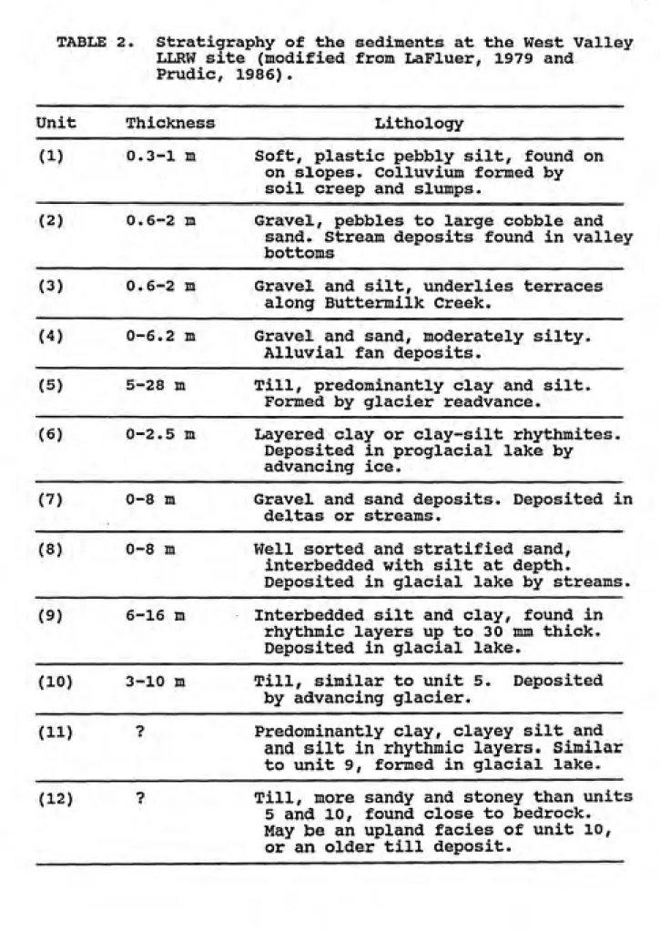
al.. 1984). The stratigraphy of the sediments is given in
Table 2. A geologic cross-section and its location are
shown in Figures 6 and 7.
The bedrock, which underlies the Wisconsin till
complex, is composed of Devonian Canadaway Group siltstones
and shales approximately 300 m (984 ft) thick. These rocks dip southward at 6 to 8 m/km . The bedrock shows no
faulting or folding in the upper layers (upper 180 m), but joints or fractures are common. This bedrock later served as parent material for the till complexes deposited during
the Wisconsian age glaciation and generally 85 to 95 percent
of the pebbles in the till are fragments of the local shales
and siltstones (Prudic, 1986).
The till complex includes an upper till, kame deltas,
lacustrine sequence, a lower till, and the bottom lacustrine
deposit. The sediments in this region were deposited by the
advancing ice sheets or the associated meltwater; the
shales and siltstones of the Devonian bedrock being the
primary source. Temporary glacial lakes formed in the
valleys as glaciers blocked the northward drainage of
streams, trapping large volumes of silt and clay. Some of
30
TABLE 2. Stratigraphy of the sediments at the West Valley
LLRW site (modified from LaFluer, 1979 andPrudic, 1986).
Unit Thickness Lithology
(1) 0.3-1 m Soft, plastic pebbly silt, found on on slopes. Colluvium formed by
soil creep and slumps.
(2) 0.6-2 m Gravel, pebbles to large cobble and
sand. Stream deposits found in valley
bottoms
(3) 0.6-2 m Gravel and silt, underlies terraces along Buttermilk Creek.
(4) 0-6.2 m Gravel and sand, moderately silty. Alluvial fan deposits.
(5) 5-28 m Till, predominantly clay and silt. Formed by glacier readvance.
(6) 0-2.5 m Layered clay or clay-silt rhythmites.
Deposited in proglacial lake by
advancing ice.
(V) 0-8 m Gravel and sand deposits. Deposited in
deltas or streams.
(8) 0-8 m Well sorted and stratified sand, interbedded with silt at depth.
Deposited in glacial lake by streams.
(9) 6-16 m Interbedded silt and clay, found in
rhythmic layers up to 30 mm thick.
Deposited in glacial lake.
(10) 3-10 m Till, similar to unit 5. Deposited by advancing glacier.
(11) ? Predominantly clay, clayey silt and and silt in rhythmic layers. Similar
to unit 9, formed in glacial lake.
(12) ? Till, more sandy and stoney than units
5 and 10, found close to bedrock. May be an upland facies of unit 10,
450 > Ui -J < m M UJ > O CQ < cc lU 2 Q 3 350 B1
proiecied-B2 \
projected
420 U
Continued
elow
400
t-390 H
380 h
450 440 430 420 410 400 390 380 370 360 350
- Burial Hole A
Trenches /
Hole J Hole V
Franks
DH-7
projected
Section A
Covered
L 19) v.\ Buttermilk
30 60 90 120 METERS _J____I____I____I
Vertical exaggeration x 2.5
EXPLANATION
Hole A,
Hole J, Hole V.
DH-7
B1, B2, etc.
©©.
Measured geologic section
Hole drilled for USGS study
Test boring drilled in 1962 as part of
sue evaluation, drive-spoon samples
examined by geologist.
Test boring drilled for engineering de¬
sign of proposed structures; log by
Empire Soils Investigations, Inc. Lithostratigrapfiic units, described in
table 2.
Macro-scale folding
(0.3-m amplitudel
T Till, silty clay matrix t Till, stony silty clay
G Gravel
S Fine to coarse sand
F Fine to very fine sand
L Silt
Y Clay
* Log inferred from geopliysical data
and other wells
^> Top of bedrock
32
78 40' 78 39' 78°38'
42' 29' — \ —»^/.__-'
\0.
42 28'
42 27'
42 26'
78 37'
.-f"
ͣ
<£!'- f-.'-^--^ /-__
EXPLANATION
A STREAM-GAGING STATION
1L MEASURED GEOLOGIC SECTION WITH I IDENTIFICATION-Some sections are, de¬
scribed in Randall (1980), others are unpub¬
lished.
O WELL OR TEST HOLE
DH6
B2 Geologic test hole
V
20-59 Seconds of latitude followed by seconds of
longitude, identifies wells sampled for chemical analysis (with degrees and minutes in table 1).
LINE OF GEOLOGIC SECTIONS-Shown in figure 9.
WESTERN NEW YORK NUCLEAR SERVICE
CENTER BOUNDARY
flEPROCESSING CENTER
CH+3 Burial ^ rFren'cfi'es
36.57-- 36-43 ^Ki 37-23<'» DH6 AdM4
.»?a?-a:„,..
0 25-07
Base from U. S. Geological Survey
Ashford Hollow 1:24,000, 1964
0.5 KILOMETER
-i—^-^
0.2 0.4 0.6 MILE
Figure 7. Location of cross-section, streams, and
these lacustrine deposits have been preserved while others
were eroded as glaciers advanced over them. Sands and
gravel were deposited locally, primarily in deltas where streams entered glacial lakes and on alluvial fans of streams that developed during interglacial periods
At the disposal site the trenches are located in the
upper till. This till which is approximately 28 m (92 ft) thick, is composed predominantly of clay and slit; cores taken from the burial site contained 50 percent clay, 27
percent silt, 13 percent sand and 10 percent fine gravel on the average. Distributed randomly throughout the till are pods and irregular lenses of stratified sand and gravel and rhythmic silt and clay (Prudic, 1986). This till unit was
deposited by a tongue of ice that readvanced as far south as West Valley. Lafleur (1979) has correlated this readvance
with the Lavery readvance in Ohio. During this readvance
the glacier apparently floated free from the substrate and
allowed beds of silt and clay to accumulate.
Beneath the Lavery till, Kame deltas up to 8 m (26 m) thick occur in the burial site vicinity. These units are not continuous and are randomly located. When present, this
sequence is composed of pebbles and small cobbles and is
absent near the burial site. Deposits east and southeast of
the site may have originated as deltas in a declining
postglacial lake or as an alluvial fan deposit which spread
34
The next unit is the lacustrine sequence which has an approximate thickness of 12 m (39 ft) beneath the burial
site. The lacustrine deposit consists of interbedded coarse silt, fine silt, and clay in rhythmic layers. This unit is
typical of bottom deposits in a glacial lake characterized
by icebergs and occasional readvances of a floating or
grounded ice tongue. This unit is found in all cores which
penetrate the Lavery till and Kame deltas.
The next unit is a till similar to the Lavery till
which was deposited during a readvance of a glacier during
the Kent readvance. This unit is approximately is
approximately 3 to 10 m (10 to 33 ft) thick in the burial
site vicinity and is composed predominantly of sand and silt
with some deformed slivers of coarse silt interbedded.
Postglacial erosion began during the Holocene (9,900 to 13,000 years ago). Immediately after retreat of the last
glacier and the subsequent drainage of postglacial lakes,
meltwater from ice to the north and runoff from the
hillsides spread gravel over large areas of the Cattaraugus Creek basin, including the Buttermilk Creek valley. The
incision by Cattaraugus Creek initiated erosional processes
which continue to the present.
the long term, larger landslides will eventually encroach on
site boundary (Albanese et al..1984).
Hydroloqic Characteristics
Surface Water
The West Valley Burial site lies entirely within the Buttermilk Creek drainage basin. Franks Creek, a tributary
to Buttermilk Creek, drains the east, south and southwest
parts of the burial site (Fig 7); an unnamed tributary to Franks Creek drains the north and northwest sections.
The climate at the West Valley burial site is humid continental, with annual precipitation averaging 100 cm
(39.4 in). Most of the runoff from the burial site flows
into Lake Erie via Franks Creek, Buttermilk Creek, and
Cattaraugus Creek or returns to the atmosphere by
evapotranspiration.
Ground Water
The stratigraphy of the materials at the LLRW site
plays an important role in the movement of ground water.
36
saturated and provide a migration pathway for lateral flow
through the coarse sediments, eventually discharging into
the bluffs along Buttermilk Creek. The unsaturated
conditions in the lacustrine units result from low vertical permeability of the Lavery till and thus, result in low
recharge through the till. The lacustrine sequence acts as a drain to the Lavery till and produces downward hydraulic
gradients.
Information from a well drilled on the eastern side of
the disposal site, shows that the depth to ground water is
31 to 38 m (102 to 125 ft) and is located in lacustrine
sediments. Trenches at West Valley were dug to a depth of 6
m (20 ft); the trench bottoms lie from 25 to 32 m (82 to 105 ft) above the water table (Clancy et al.. 1981). This
aquifer does not yield usable quantities of water. The
shattered upper section of the Devonian is the major aquifer
in this stratigraphic sequence.
Detailed studies of the LLRW disposal site hydrology
have been confined to the Lavery till since the trenches are
located in the till. Trench covers were constructed from
reworked till, and studies (Prudic, 1986) show that
radionuclide migration has not extended through or beyond the Lavery till. The Lavery till is not a homogeneous body,
but composed of a weathered section, a unweathered section, and distorted lenses of stratified sand an gravel.
average porosity of 32.4 percent. Analysis of thin sections
show no preferred orientation of clay grains and suggests little anisotropy. Field and laboratory tests have measured
a hydraulic conductivity that ranges from 2 x 10"^ cm/s
(5.67 X 10"^ ft/d) to 6 X 10"^ cm/s (1.7 x 10"'* ft/d) in the
unweathered till.
The upper 2 to 3 m (7 to 10 ft) of till is weathered and contains intersecting features. These fractures have
firm oxidized borders and extend down approximately 5 m (16
ft) to the unweathered till (Prudic and Randall, 1979). Computer simulations of ground water flow indicate the weathered till is ten times more permeable than the unweathered till.
Randomly distributed lenses or pods of silt, sand, and clay are found in the Lavery till. These distorted lenses of stratified material make up approximately 7 percent of
the total mass of sediments. These units are discontinuous, deformed and randomly rotated. Values for hydraulic
vertical and hydraulic conductivity vary from 3 x 10~° cm/s
(8.51 x 10"-^ ft/d) to 6 X 10"^ cm/s (1.7 x 10"^ ft/d), two
orders of magnitude greater than the unweathered till.
The hydraulic gradient in the till surrounding the LLRW
site is predominantly downward. In general, ground water
38
lacustrine sediments until discharging along Buttermilk
Creek. Figure 8 shows an idealized view of ground water
flow in the vicinity of the LLRW disposal site. Computer simulations of possible ground water flow at West Valley
suggest that water leaving a trench would take 300 to 2,300
years to travel 23 m (75 ft) to the underlying lacustrine
sequence. The shortest distance for surface discharge is 840 m (2,756 ft) and this would require an additional 500 years.
Problems Encountered
Water levels in the trenches have been monitored
regularly since 1966 by Nuclear Fuel Services, Inc.
Significant increases in water levels in trenches 3 through 5 (north site) was observed in 1971. In March 1975, trench water seeped out through the trench cover along the side of
trench 5 and the northern end of trench 4. The burial of
commercial LLRW was stopped after the discovery of this seep. From March 1975 through October 1976, approximately 6.4 million liters (1.69 million gal) of leachate was pumped
from trenches 3, 4 and 5 (Clancy et al.. 1981). Leachate was transferred to the on-site reprocessing plant for
Precipitation
Precipitation
Evapotranspiration
Swamp
Creek
Buttermilk Creek 9
Not To Scale
EXPLANATION
n
n
SATURATED
UNSATURATED
i DIRECTION OF WATER MOVEMENT
Length and number of arrows suggest relative magnitude
____WATER TABLE
--- CONTACT BETWEEN UNITS
STRATIGRAPHIC UNITS From table 4
2, 3,4,7 Gravel, coarse sand 9 Silt, clay
8 Fine sand, silt 5, 10 Till
Figure 8, Idealized ground-water flow at West Valley
40
The principal cause of the water accumulation in the trenches at West Valley was the infiltration of
precipitation through the trench covers rather than from
ground-water seepage from the till. Seasonal drying and
subsidence from waste decomposition resulted in cracks forming in the trench covers. These cracks provided
efficient pathways for precipitation to the trench. The low
permeability of the till coupled with the normal
precipitation rate, prohibited rapid migration of the trench water and resulted in the accumulation of large volumes of water.
Radiochemical analysis indicates the trench leachate is contaminated from the buried LLRW. Gross alpha activity
ranges from 8.9 x 10~^ to 8.2 x 10~^ uCi/mL. Gross beta
activity ranges from 7.6 x 10"^ to 3.1 x 10"^ uCI/mL. The
concentration of tritium varies from 3.1 x 10"^ to 4.3
uCi/mL. The major gamma emitting radionuclides found in the
leachate are ^^"^Cs, ^^^Cs, ^°Co, and ^^^ksa. The
concentration of •'•
ͣ
^^Cs ranges from 4.9 x 10" to 1 x 10"
uCi/mL and ^•^'*Cs ranges from 6.4 x 10"^ to 1.3 x 10"^
fin f —7
uCi/mL. The concentration of ^Co varies from 9.9 x 10 to
7.0 X 10"^ uCi/mL. The smallest concentrations are for
^^•'•Am, this value ranges from 2.1 x 10"^ to 2.0 x lO"
UCi/mL (Prudic, 1986).
Radionuclide migration is evaluated primarily on
information from cores taken alongside and beneath trenches
Radionuclide migration can occur both laterally and downward from the LLRW trench sites. At West Valley migration has
occurred both outward and downward, but not at significant
rates to endanger the public.
Analysis of cores taken from 29 test holes at distances of 2.5 to 5m (8.2 to 16.4 ft) from the burial sites (Prudic and Randall, 1979) indicates that triti\am has migrated
laterally approximately 2.5m (8.2 ft) through the
unweathered till at two sites. Lack of widespread lateral
migration of tritium supports the conclusion that migration
is primarily downward at West Valley. Lateral flow from
trenches occurs only when water levels in the trench
intersect the more permeable weathered till or the reworked
till used in constructing the cover.
Cores collected beneath trenches 4, 5, and 8 indicate
the downward migration of radionuclides from the trenches at West Valley. The principal radionuclides that have migrated
downward at this site are tritium, "'
ͣ
^C, and ^^Sr; the
remaining radionuclides identified in the leachate do not show significant migration. Tritium is the most mobile
radionuclide of those buried and has been detected to a
depth of 3 m beneath trench 8. Cores taken from trench 5
show that -'
ͣ
^C has migrated up to 1 m beneath the trench
floor. Strontium-90 was detected beneath trenches in only a few cores and its downward migration varies 0.14 m to 0.70 m
42
Since the movement of ground water and radionuclides at
West Valley is primarily downward, Prudic (1986) uses a one
dimensional model to determine migration rates for tritium,^°Sr, and ^'*C. The maximum distance tritium is predicted to
migrate after 100 years ranges from 10 to 14 m (33 to 46 ft)
depending on model parameters. Due to this slow migration
rate, tritium is confined to the weathered till andunlikely to discharge into Buttermilk Creek. Models
indicate that the maximum distance that ^°Sr can migrate and
still be detected is between 3 to 6 m (10 to 20 ft) in 500 years. This migration rate is smaller than the value for
tritium and is attributed to the sorption of ^Sr on the
till particles and a smaller diffusion coefficient. Carbon-14 would require between 1500 to 20,00 years to travel 23 m
(75 ft) to the saturated lacustrine sediments.
Migration of radionuclides at West Valley is severely
limited by the geologic and geohydrologic characteristics of
the site. The low permeability and thickness of the unweathered till has retarded radionuclide migration.
Radionuclides are unlikely to reach the environment through subsurface migration. There has been no significant
migration of radionuclides through the ground water and no
significant problems with surface contamination. The major
problem at West Valley has been the accumulation of leachatewithin the burial trenches. Cracks in the trench covers
facilitate infiltration of precipitation though the low
SHEFFIELD, ILLINOIS
Site History
The Sheffield LLRW disposal site is located
approximately 5 km (3.1 mi) southwest of the town of
Sheffield, Illinois (Fig. 9). The facility began accepting
commercial LLRW in August 1967 and was operated byCalifornia Nuclear, Inc.. In March 1968 the operating
license was transferred to Nuclear Engineering Company, Inc. (NECO), presently U.S. Ecology Inc. In 1975, NECO requested
a modification to its license that would allow the
construction of compacted fill trenches which were intended
to increase the capacity and burial lifetime of thefacility. The Nuclear Regulatory Commission (NRC) approved
construction of compacted fill trenches but withheld
approval for waste burial in these new trenches. In 1976,
U.S. Ecology filed an application to the NRC and the State
44
B9°50' 89°30'
4r30'
WHITES!DE LEE COUNTY
BUREAU COUNTY
92
MINERAL
AWAN
<X1SHEFFIELCN
leld I #
PRINCETON
BUOA
NEPONSET
TISKILWA
HENNEPIN KEVM^klHE
j ~
STARK COUNTY4ri0'
_J
MARSHALL COUNTY
lO MILES
I
ILLINOIS
Figure 9. Location of Sheffield disposal site
Sheffield facility (National Low-Level Radioactive Waste Management Program, 1982).
Shallow land burial was the disposal technology used at the Sheffield site. At the time of closure 22 trenches had
been constructed and filled with LLRW. Typical trench
dimensions range from 40 to 80 m (131 to 262 ft)in length,
12.2 to 24.4 m (40 to 80 ft) in width, and 6.1 to 12.2 m (20 to 40 ft) in depth. Nineteen of the trenches were excavated
leaving a minimum of 3 m between the trench bottom and the
saturated zone. Two of the trenches were constructed above
the existing surface grade by constructing walls of compacted silty-clay (Clancy et al., 1981).
From 1976 until 1978, LLRW was buried in the 21
trenches at the Sheffield facility. During this period,
approximately 90,513.1 m"^ (3,196,017 ft^) of waste was
buried. This included 60,205 Ci of by-product material, 54
kg of special nuclear material, and 270,840 kg of source
material (Healy et al.. 1986). Although disposal has ceased
at Sheffield, radionuclide migration and general upkeep of
the site continues in this shutdown mode.
Geologic Characteristics
The Sheffield LLRW facility in located in rolling
terrain underlain by Pleistocene glacial deposits that
46
glacial deposits overlie Pennsylvanian shale approximately 137 m (449 ft) thick (Clancy et al.. 1981). A generalized cross-section (Fig. 10) shows the stratigraphic relationship
of the various rock units beneath the LLRW site. The
location of the cross-section is given in Figure 11.
Beneath the glacial deposits lies a section of the
Carbondale Formation of the Pennsylvanian period. This
section is composed predominantly of mudstones and
fossiliferous shales. Samples of weathered shale range from
silty clay to a clayey silt. This thick sequence of shale and mudstone isolates the regional ground-water aquifers
from the hydrologic system of the overlying glacial
sediments.
The Pleistocene glacial sediments lie unconformably
over the Pennsylvanian bedrock. The glacial deposits are composed of Glasford Formation, the Roxana Silt, the Peoria
Loess, and fill. The Glasford Formation is further divided
into: the Duncan Mills Member, the Hulick Till Member, the Toulon Member, the Randor Till Member, and the Berry Clay Member (Foster et al.. 1984).
The oldest glacial sediments are the Duncan Mills
Member. These sediments are a thick sequence of lacustrine
deposits formed during the Illinoian ice age. The Duncan
Mills Member consists of silty clays interbedded with silt,
clay and sandy silt layers. This section is found in the
bottoms of old valleys and reaches a maximum thickness of
710
FILL
PEORIA LOESS
RADNOR TILL TOULON
MBR (PEBBLY SAND)
TOULON
PEORIA LOESS
^ 730
CARBONDALE FORMATION
(SHALE)
HULICK TILL MBR
h770
h750
-730
-710
100
_l___
200 ___1___
300 FEET
VERTICAL EXGGERATION X5
EXPLANATION
CLASF08D FORMATION 526 US6S WELL •- Projected to
1ine of section
Figure 10, Geologic cross-section of the Sheffield
48
6S 47"42' 4C 89 47' 21'
Jl ZO'
528 523
Base iron U.S. Geological
Survey, 1979 200 400 FEET
EXPLANATION
•510 OBSERVATION WELL AND DESIGNATION A---A' LINE OF SECTION
The Hulick Till Member overlies the Duncan Mills Member
and underlies most of the LLRW site. This unit was deposited during the Illinoian glacial period and is composed of
sands, silts, and clays. This unit has an average thickness
of 2 m (6.6 ft). In places where the glacier incorporated
more lacustrine sediments the Hulick Till has an increased silt content.
The Toulon Member overlies the Hulick Till Member. The
Toulon Member is an outwash plain deposit of the Illinoian glacial period. These outwash sediments grade from
moderately-sorted pebbly-silty sands at the western site area to well-sorted pebbly sands in the eastern area. The
Toulon Member is approximately 5 m (16.4 ft) thick and is
absent in the southwest and northwest sections of the LLRW site.
During the final stages of the Illinoian glacial
period. The Randor Till Member was deposited. This unit overlies the Toulon and is approximately 3 m (9.8 ft) thick
when present. This till unit consists of interbedded clayey-silts and non-continuous sand-silt lenses. The
Randor Till Member is distinguished from the Hulick Till Member by its higher clay content, 72 percent to 56 percent
(Foster et al., 1983).
Overlying the Randor Till Member in the upland areas of the site is the Berry Clay Member. The Berry Clay Member was formed during the Sangamonian Stage after the Illinoian
50
formed by the in-situ weathering of the Randor Till Member
(Willman and Frey, 1970).
During the Wisconsian Stage, continental ice sheets did not cover this area of Illinois and, therefore, the
characteristic till and lacustrine sediments are absent.
Aeolian sands and silts were deposited at this time and are
represented at the Sheffield site by the Roxana Silt and the
Peoria Loess. The source material for these units was the
lake deposits along the Mississippi River and the outwash plains. The Roxana Silt is composed of Lower Wisconsian Silts and ranges from .4 to 2.2 m (1.3 to 6.6 ft) in
thickness. The overlying Peoria Loess, Middle to Upper Wisconsian, covers the entire site and ranges in thickness
from .6 to 9.1 m (1.9 to 29.8 ft) (William and Frey, 1970). The present soil is from the weathering of the Peoria Loess. This soil is predominantly a clayey silt and, when
present, varies in thickness from 0.6 to 2.7 m (2 to 9 ft).
In the construction of the burial trenches, the soil has
been removed or covered by fill. The fill is the youngest
unit at the LLRW site and consists of clayey silt to silt.
This material was used in trench cap construction and in the
filling of low areas. Thickness of the fill varies from 0.6
to 7.1 m (2 to 23.3 ft) depending on the site area (Foster
Hvdroloqic Characteristics
Surface Water
The Sheffield LLRW facility lies within the headwater tributaries of Lawson Creek, which at its nearest point is 1.6 km (.99 mi) east of the site. Surface water drains from
the site by three streams which discharge into Lawson Creek.
Flow from the Lawson Creek eventually reaches the Mississippi River.
Northwest Illinois's climate is humid continental, with
warm summers and cold winters. Precipitation averages 89.1
cm/yr (35 in/yr) (Healy et al.. 1985). This value is broken
down into recharge to the saturated zone (6.2 cm), surface
runoff (22.9 cm ), and evapotranspiration (60 cm ).
Ground Water
The variable lithology of the glacial sediments that
overlie the Pennsylvanian bedrock provides a complex
hydrologic system at Sheffield. The site hydrologic system
is composed of glacial sediments from the ground surface to
the bedrock. The unsaturated zone and the shallow saturated
zone are contained within the glacial sediments. The deeper
regional aquifers are isolated from possible radionuclide
migration by the Pennsylvanian bedrock (Healy et al.. 1985).
Recharge of the hydrologic system is from precipitation
52
At Sheffield the unsaturated zone averages 12 m (39 ft)
in thickness. With the exception of the Duncan Member which
is always saturated, the unsaturated zone may include,
depending on site location, the Peoria Loess, Roxana Silt,
The Berry Clay Member, the Randor Till Member, the Toulon
Member, and the Hulick Till. The glacial sediments found in
the unsaturated zone have a range of textures and,
therefore, a wide range of permeabilities. The Peoria Silt
is a significant unit at this LLRW and has a an average
vertical hydraulic conductivity of 1.1 x 10" cm/s (3.1 x
10"^ ft/d) and an average horizontal conductivity of 8.8 x
10"^ cm/s (2.5 X 10"^ ft/d). Burial trenches were placed in
the unsaturated zone (with the exception of trench 18) and
rely on the sorption characteristics of this zone to impede
radionuclide flow.
In general, the glacial sediments at Sheffield have
average vertical and horizontal conductivities on the order
of 10"^ to 10"^ cm/s (10"^ to 10"-* ft/d) . The pebbly sand
of the Toulon Member is an exception, however, with
horizontal conductivity of 5.5 x 10"^ cm/s (1.6 x 10^ ft/d)
(Foster et al., 1983) . Burial trenches were placed in the
unsaturated zone at Sheffield (with the exception of trench
18) to take advantage of the low conductivities of the
sediments to impede radionuclide flow.
Ground water that moves through the soil flows
vertically downward through the Peoria Loess to the
apparently moving laterally in the unsaturated zone in
subsurface areas where the Peoria Loess contacts the
pebbly-sand unit of the Toulon Member and at the basal
contact of the Toulon Member with the Hulick Till.
This lateral movement of water in the unsaturated zone may
account for the rapid tritium migration at the southeastern
area of the site.
The saturated zone includes all glacial sediments
between the water surface and the bedrock. The saturated
zone averages 6 m (20 ft) in thickness and the water table
ranges from 6 to 15 m (20 to 49 ft) below the ground surface
(Clancy et al., 1981). Most sediments have low permeability
with the exception of the course pebbly-sand sediments.
Depending on site, the saturated zone may include the Duncan
Mills Member, the Hulick Till Member, the Toulon Member, and
the Peoria Loess.
The Duncan Mills Member is fully saturated beneath the
waste site and overlies the Pennsylvanian bedrock. The
average vertical hydraulic conductivity is 6.7 x 10"' cm/s (1.9 X 10"^ ft/d).
The Hulick Till Member acts as a semi-impermeable
barrier to vertical flow in the saturated zone. This unit
overlies the Duncan Mills Member in the valleys, and
overlies bedrock in topographically higher regions. The
—6
average vertical hydraulic conductivity is 1.5 x 10 ° cm/s
(4.3 X lO"-* ft/d) and the average horizontal conductivity is
54
The Toulon Member underlies 5.7 ha (14 acres) of the LLRW site, 4 ha (10 acres) are partially to completely
saturated. The hydraulic conductivity of this unit varies
with its lithology and ranges from 2.2 x 10"^ to 5.5 x 10"^
cm/s (6.2 X 10"2 to 1.6 X 10^ ft/d) (Foster et al.. 1983).
The difference in these values is a function of the amount of silt present in the pebble units. The pebbly-sand unit
of the Toulon Member has the highest measured conductivity and is the controlling factor in the migration of water
into, through, and across the LLRW site.
The Peoria Loess is predominantly in the unsaturated zone; however in a few locations it extends into the
saturated zone as much as 3.6 m (11.8 ft). The average
vertical hydraulic conductivity is 8.8 x 10"^ cm/s (2.49 x
10~^ ft/d) and the average horizontal conductivity is 1.1 x
10"^ cm/s (3.1 x 10"2 ft/d).
In this complex hydrologic environment, water will move faster in the lithologic units with the higher hydraulic conductivities. At the Sheffield LLRW site ground water
flows from the west to the east and mimics the surface
drainage pattern. There are two principal flow paths for this site. The primary flow path, extending from offsite
to northeast of the site, is through the saturated pebbly-sand unit of the Toulon Member. The secondary flow path is
through the silt of the Peoria Loess. Discrepancies in the
calculated and observed migration rates suggests that ground