Sharif University of Technology
Scientia IranicaTransactions B: Mechanical Engineering http://scientiairanica.sharif.edu
Impact of nonlinearity on bolt forces in multi-bolted
joints: A case of the assembly stage
R. Grzejda
Faculty of Mechanical Engineering and Mechatronics, West Pomeranian University of Technology, Szczecin, Poland. Received 10 October 2016; received in revised form 15 July 2017; accepted 16 April 2018
KEYWORDS Multi-bolted joint; Nonlinearity; FE-modeling; Assembly stage; Preload.
Abstract. This study concerns modeling, computation, and analysis of multi-bolted joints in the assembly stage. The physical joint model is introduced as the assembly of the following three basic subsystems: a set of fasteners (bolts), a exible joined ange, and a contact layer between it and a rigid support. The Finite Element Method (FEM) was used for modeling. Bolts were replaced by the bolt models of the spider type. The joined ange was modeled with spatial nite elements. As a model of the contact layer, the Winkler contact layer model was adopted. The truth of the theorem was tested, according to which nonlinear characteristics of the contact layer might have an insignicant impact on the nal computational values of bolt preloads in the case of sequential tightening of the joint. The results of the calculations for the selected multi-bolted joint are given and compared with the experimental results. Conclusions of paramount importance to the engineering practice are comprised.
© 2019 Sharif University of Technology. All rights reserved.
1. Introduction
Multi-bolted joints are made up of many bodies being in a contact [1-3]. For this reason, they are most often referred to as nonlinear systems in modeling and calculations. The origin of this nonlinearity lies in the surface texture of the joining elements, which after mechanical processing are characterised by roughness [4,5]. In fact, joining a pair of elements with rough surfaces is related to the nonlinearity of mechanical properties of the created contact joint.
However, the connection of two elements joined in a multi-bolted system is a special case of the contact joint. It can be assumed that the multi-bolted joint in the assembly stage is loaded only with normal forces derived from the preload of bolts. Taking
*. Tel.: +48 91 449 4969; Fax: +48 91 449 4564 E-mail address: [email protected] doi: 10.24200/sci.2018.20320
into account contact phenomena between the joined elements in this case, it is sucient to consider only normal characteristics of the contact joint (for a review, see [6]). Such characteristics can be represented with good approximation through exponential functions [7-9]. Progressive tightening of the bolts in the pre-tensioning process [10-12] is equivalent to gradual tight-ening of the contact layer located between the joined elements. In such a process, roughness of the surface texture of the elements has less and less inuence on mechanical properties of the contact joint. Therefore, it can be assumed that typically nonlinear character-istics of the normal deformation may be replaced by linearised counterparts. This theorem is established in the present study, which contains a continuation of the theme of modeling multi-bolted joints in the assembly stage inaugurated in the previous paper [13].
Complex multi-bolted joints are most often mod-eled and calculated using the nite element method. For modeling of the joined elements in such connec-tions, spatial nite elements are usually used. In
contrast, the bolts are replaced with various types of models. The most accurate types of these models are the 3D models of the bolts. At the same time, however, they are the most time consuming models in calcula-tions. 3D modeling strategies can be summarised in the following order:
- Use of a uniform component model linking together the bolt head, the bolt shank, and the nut [14-17];
- Use of a model consisting of the bolt head and the shank without the tread [18,19];
- Use of a full model consisting of the bolt head, the bolt shank, and the nut including the tread [20].
Sometimes there is no need to build complex bolt models. This occurs, for example, when determining the bolt preload during tightening the multi-bolted joint. It is therefore reasonable to look for simplied models. In practice, in addition to spatial models of the bolts, the following substitute bolt models are used:
- Spring and truss models [21-23];
- Rigid body bolt models composed of a exible bolt shank and a rigid bolt head [24-27];
- Bolt models of the spider type [28,29].
As it is written above, the systemic approach to modeling multi-bolted joints enables modeling each of the subsystems individually using models of varying complexity in order to nd the best of them. This applies to particular bolts. Some theoretical studies on the process of pre-tensioning of the asymmetrical multi-bolted joint, consisting of a ange xed to a rigid support, have been introduced in the previous paper [13]. The bolts were treated as elements with a rigid head in that study. This paper is a continuation of the work just mentioned. It presents the results of modeling the pre-tensioning process for the modied joint model also using the nite element method, but with other models of bolts. The bolts are now regarded as bolt models of the spider type [28].
Modeling and calculations of a linear multi-bolted joint model should be considered in two stages. This paper describes the model in the assembly condition. The model in the operational condition is presented in a separate paper [30].
2. Model of the joint based on the system approach
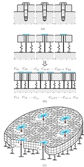
The concept of the modeling method of multi-bolted joints used in this paper is presented in [13]. The joint model is made up of a exible ange that is connected to a rigid support using k bolts, as shown in Figure 1. The bolts are replaced by bolt models of the spider type [28] with the stiness coecient cyi(where
Figure 1. Model of the joint: (a) Diagram, (b) spring properties of the joint elements, and (c) nite element model.
i = 1; 2; ; k). The essence of each such bolt element is that their shank is modeled by means of the beam element with a cross-sectional dimension corresponding to the size of the bolt; however, its head is modeled with use of several beams built as a spider connecting the nodes lying in the real bolt in the bolt head area and having a total volume, such as the volume of the real bolt head.
The Winkler elastic foundation model [31] is added between the joined elements as a model of the contact layer. This type of contact layer model can be characterised by l one-sided linear springs with the stiness coecient czj (where j = 1; 2; ; l). It is
dened by the following function:
Rmj= Aj f(j); (1)
of the elementary contact area no. j (N), Aj is the
elementary contact area no. j (mm2), and j represents
the deformation of the linear spring no. j (m) located in the contact layer.
The contact layer model springs pose a exible contact model and join the surfaces of the exible ange and the rigid support. Thus, the surfaces of the joined elements are not in direct contact. They are separated by the contact layer, made up of springs. During the calculation process, the springs that are not loaded in the current step are excluded from the model.
The equilibrium equation of the system shown in Figure 1 can be represented as:
K q = p; (2)
where K is the stiness matrix of the multi-bolted system, q is the displacements vector of the multi-bolted system, and p denotes the loads vector of the multi-bolted system.
The following three dierent subsystems can be identied in the discussed multi-bolted joint:
- Subsystem made up of the bolts, referred to as subsystem B;
- Subsystem associated with the exible ange re-ferred to as subsystem F;
- Conventional contact layer subsystem referred to as subsystem C.
Then, Eq. (2) can be expressed in the form: 2
4KKBBF B KKBFF F K0F C 0 KCF KCC
3 5
2 4qqBF
qC
3 5 =
2 4p0B
0 3
5 ; (3) where KBB, KF F, and KCC are stiness matrices of
subsystems B, F, and C; KBF, KF B, KF C, and KCF
are matrices of elastic couplings among subsystems B, F, and C; qB, qF, and qCare displacements vectors of
subsystems B, F, and C; and pB represents the loads
vector of subsystem B.
Thanks to such a multi-bolted joint model, forces in the bolts can be determined both during and after the assembly of the joint.
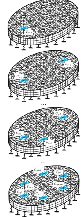
The pre-tensioning process is an iterative process, which is composed of k steps, in pursuance of the sum of bolts forming the multi-bolted joint (Figure 2). The process starts from tightening the rst bolt. Therefore, the system consists of a ange supported on a linear elastic foundation and is only clamped with a single bolt. In the rst step, the system is loaded with the preload of the bolt no. 1, i.e., with the force Fm1.
As a result of the solution to Eq. (3), the vector of displacements of linear springs qC:
qC= col(qC1; qC2; ; qCj; ; qCl); (4)
is obtained. It contains the initial deformation of linear springs for the next step of the calculation process.
Figure 2. Pre-tensioning process of the multi-bolted joint.
In the following joint tightening steps (when i = 2; 3; ; k), in the system, the next spider bolt model is activated. This also causes that the stiness matrix of the bolts subsystem KBBin Eq. (3) is supplemented
by the element that corresponds to the bolt model added in the current calculation step. Besides, it should be noted that in the current step of joint tightening, the stiness matrix K is inter alia composed of the following two parts:
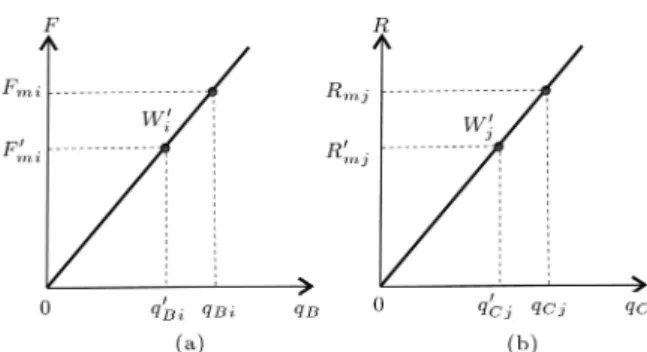
Figure 3. Determining of the load: (a) For the bolts and (b) for elements of the contact layer [13].
- The variable stiness matrix KCC.
The nal linear springs displacements, qCj, in the
current step of the joint tightening are determined from the operating points, W0
j, which denote their state
of deformation in the previous calculation step (Fig-ure 3(b)). Using qCj identied by the displacements
in this method, the forces Rmj can be designated from
Eq. (1) for j equal to qCj. The calculation process
is kept running in k iterations to achieve the values of the contact layer forces at which the following condition will be fullled:
R0mj Rmj
Rmj
; (5)
where denotes the admissible error of the calculation process.
When Eq. (3) is solved, also the displacements vector of bolts qB:
qB= col (qB1; qB2; ; qBi; ; qBk) ; (6)
is obtained.
The nal bolts displacements qBi in the current
step of the joint tightening are determined from the operating points, W0
i, which denote their state of
deformation in the previous calculation step (Fig-ure 3(a)). Using qBi identied by the displacements
in this method, the bolt forces Fmi can be computed
on the basis of the formula:
Fmi= cyi qBi: (7)
A block diagram of the iterative process of calculating the multi-bolted joint is illustrated in Figure 4.
3. Results of multi-bolted joint calculations In reference to the described method, the calcula-tions for the exemplary asymmetric multi-bolted joint
Figure 4. Block diagram of iterative calculations of the multi-bolted joint.
formed by seven M10 bolts were carried out. This joint was tested on a laboratory stand and the test results are described in reference [32]. A simplied FE-model of the joint and the numbering and positioning of the bolts are illustrated in Figure 5(a). Calculations were performed for the ange having a thickness of 20 mm. The model of the joint has been fastened in the manner, shown in Figure 5, by:
- Receiving degrees of freedom in all directions at the bottom of the conventional contact layer;
- Receiving degrees of freedom in a plane perpendic-ular to the axis of the bolts in ve nodes on the circumference of the ange.
In this case, the bolts preload Fmi is 20 kN. The
sequence of the bolts tightening is given in Table 1. It is one of the four tightening sequences tested in [32],
Table 1. Tightening sequence of the joint.
Number of the bolt 1 2 3 4 5 6 7
Figure 5. Adopted multi-bolted joint: (a) FEM-based model and (b) fastening of the model.
for which the smallest scattering of preload values in the bolts at the end of the pre-tensioning process has been achieved. The tightening procedure was performed in one pass. However, it is possible to carry out this procedure in a few passes, for example following the recommendations given in [33]. Linear characteristics of the springs forming the contact layer are specied by the following function dened on the basis of experimental tests [13]:
Rmj= Aj (26:873 j): (8)
The calculation results are presented in the graphs shown in Figure 6, in which force variations in the bolts during the pre-tensioning process are presented according to the following scheme:
- In line no. 1 - the preload variations in the rst pre-tensioned bolt (no. 1);
- In line no. 2 - the preload variations in the second and the seventh pre-tensioned bolts (marked with numbers 4 and 5);
- In line no. 3 - the preload variations in the third and the sixth pre-tensioned bolts (marked with numbers 7 and 2);
- In the last line - the preload variations in the fourth and the fth bolts (marked with numbers 3 and 6).
The scattering of the nal bolts preload values can be seen by reading the preload values in bolts after
Figure 6. Preload values during the pre-tensioning process.
tightening of the bolt no. 5 on the individual graphs shown in Figure 6.
By observing the obtained results, it can be seen that the bolts preload values are irregularly variable during the entire pre-tensioning process. Adoption of the proposed multi-bolted joint model may cause vari-ability of the bolt preloads during the pre-tensioning process in the range from 8:7% to 1.4% in relation to their initial values.
The calculated values of each bolt preload during and at the end of the pre-tensioning process are compared with their experimental values [32]. The relative evaluation of the nal bolts preload values can be carried out using the Z rate:
Z =FmiFEM FmiEXP
FEXP mi
100; (9)
where FFEM
mi represents the nal preload of the ith bolt
following the linear FE-model of the multi-bolted joint and FEXP
mi is the nal preload of the ith bolt obtained
experimentally [32].
The results summarized in Figure 6 show that adoption of a linear multi-bolted joint model is
gen-erally associated with the achievement of the preload in bolts reduced relative to the values determined experimentally. A detailed extension of this conclusion can be derived from the Z rate. Based on its values, it can be concluded that the adoption of the proposed multi-bolted joint model may cause a change in the nal bolt preloads up to 8:3% by comparison with their experimental values [32].
4. Conclusions
The performed calculations and analyses lead to the following general conclusions:
1. In the face of the tightening of multi-bolted joints, nonlinear characteristics of the layer at the contact between the joined elements may have an insignif-icant impact on the nal computational values of bolt preloads. Therefore, linear models of the contact layer between the joined elements can be used to calculate and analyse such joints. Then, the task becomes less complex and its solution becomes more ecient and less time consuming;
2. The resulting calculation procedures can be used to optimize the preload of the individual bolts in order to ensure uniform pressure distribution at the interface between elements connected in the multi-bolted joint;
3. The multi-bolted joint model can be used success-fully in the analysis of the preload variance of the connections in accordance with the adopted assumptions of the model. In addition, the scope of application of the calculation method can be extended to the case of joints made from a pair of exible joined elements. The results of studies on this theme will be published in future papers.
Nomenclature
Aj Elementary contact area no. j (mm2)
cyi Stiness coecient of the bolt model
no. i (N/mm)
czj Stiness coecient of the linear spring
no. j (N/mm)
Fmi Preload of the bolt no. i (kN)
K Stiness matrix of the multi-bolted system
p Loads vector of the multi-bolted system
q Displacements vector of the multi-bolted system
Rmj Force located in the geometric center
of the elementary contact area no. j (N)
Z Accuracy rate (%) Greek symbols
Admissible error of the calculation process
j Deformation of the linear spring no. j
located in the contact layer (m) Superscripts
0 Calculation step with the number i 1
Subscripts
B Set of bolts
C Linear contact layer F Flange
i Sequence number of the bolt (where i = 1; 2; ; k)
j Sequence number of the linear spring (where j = 1; 2; ; l)
Acronyms
EXP Experiment
FEM Finite Element Method
References
1. Abid, M. \Stress variation in the ange of a gasketed ange pipe joint during bolt up and operating condi-tions", Sci. Iran., 13(3), pp. 303-309 (2006).
2. Ascione, F. \A preliminary numerical and experimen-tal investigation on the shear stress distribution on multi-row bolted FRP joints", Mech. Res. Commun., 37(2), pp. 164-168 (2010).
3. Tsiampousi, A., Yu, J., Standing, J., Vollum, R., and Potts, D. \Behaviour of bolted cast iron joints", Tunn. Undergr. Sp. Tech., 68, pp. 113-129 (2017).
4. Palasti-Kovacs, B., Sipos, S., and Bro, S. \The mysteries of the surface. First part: The characteristic features of the microgeometry of the machined sur-face", Acta Polytech. Hung., 11(5), pp. 5-24 (2014). 5. Wang, L., Liu, H., Zhang, J., and Zhao, W. \Analysis
and modeling for exible joint interfaces under micro and macro scale", Precision Engineering, 37(4), pp. 817-824 (2013).
6. Abdo, J. \Modeling of frictional contact parameters of mechanical systems", International Journal of Applied Mechanics and Engineering, 11(3), pp. 449-465 (2006). 7. Grudzinski, K. and Kostek, R. \An analysis of non-linear normal contact microvibrations excited by a harmonic force", Nonlinear Dynam., 50(4), pp. 809-815 (2007).
8. Kostek, R. \An analysis of the primary and superhar-monic contact resonances - Part 2", J. Theor. Appl. Mech., 51(3), pp. 687-696 (2013).
9. Misra, A. and Huang, S. \Eect of loading induced anisotropy on the shear behavior of rough interfaces", Tribol. Int., 44(5), pp. 627-634 (2011).
10. Abid, M., Khan, A., Nash, D.H., Hussain, M., and Wajid, H.A. \Simulation of optimized bolt tightening strategies for gasketed anged pipe joints", Procedia Engineer., 130, pp. 204-213 (2015).
11. Abid, M. and Nash, D.H. \Structural strength: Gas-keted vs non-gasketet ange joint under bolt up and operating condition", Int. J. Solids Struct., 43(14-15), pp. 4616-4629 (2006).
12. Grzejda, R. \Modelling nonlinear multi-bolted connec-tions: A case of the assembly condition", 15th Int. Sci. Conf. Engrg for Rural Dev., Jelgava, Latvia, pp. 329-335 (2016).
13. Grzejda, R. \Non-linearity of the contact layer between elements joined in a multi-bolted connection and the preload of the bolts", Combustion Engines, 55(2), pp. 3-8 (2016).
14. B lachowski, B. and Gutkowski, W. \Eect of damaged circular ange-bolted connections on behaviour of tall towers, modelled by multilevel substructuring", Eng. Struct., 111, pp. 93-103 (2016).
15. Hu, F., Shi, G., Bai, Y., and Shi, Y. \Seismic performance of prefabricated steel beam-to-column connections", J. Constr. Steel Res., 102, pp. 204-216 (2014).
16. Kalogeropoulos, A., Drosopoulos, G.A., and Stavroulakis, G.E. \Thermal-stress analysis of a three-dimensional end-plate steel joint", Constr. Build. Mater., 29, pp. 619-626 (2012).
17. Keikha, H. and Mod, M. \On the assessment of a new steel bolted ush end-plate beam splice connection", Sci. Iran. Trans. A, 24(4), pp. 1735-1750 (2017). 18. Esfahanian, A., Mohamadi-Shooreh, M.R., and Mod,
M. \Assessment of the semi-rigid double-angle steel connections and parametric analyses on their initial stiness using FEM", Sci. Iran., Trans. A, 22(6), pp. 2033-2045 (2015).
19. Sim~oes, R., Jord~ao, S., Diogo, J., and Fernandes, J. \Development and design of a concealed splice joint conguration between tubular sections", Eng. Struct., 137, pp. 181-193 (2017).
20. Pavlovic, M., Markovic, Z., Veljkovic, M. and Bu¡evac, D. \Bolted shear connectors vs. headed studs be-haviour in push-out tests", J. Constr. Steel Res., 88, pp. 134-149 (2013).
21. Li, Z., Soga, K., Wang, F., Wright, P., and Tsuno, K. \Behaviour of cast-iron tunnel segmental joint from the 3D FE analyses and development of a new bolt-spring model", Tunn. Undergr. Sp. Tech., 41, pp. 176-192 (2014).
22. Luan, Y., Guan, Z.-Q., Cheng, G.-D., and Liu, S. \A simplied nonlinear dynamic model for the analysis of pipe structures with bolted ange joints", J. Sound Vib., 331(2), pp. 325-344 (2012).
23. Smolnicki, T., Derlukiewicz, D., and Stanco, M. \Evaluation of load distribution in the superstructure rotation joint of single-bucket caterpillar excavators", Automat. Constr., 17(3), pp. 218-223 (2008).
24. Aguirrebeitia, J., Abasolo, M., Aviles, R., and de Bustos, I.F. \General static load-carrying capacity for the design and selection of four contact point slewing bearings: Finite element calculations and theoretical model validation", Finite Elem. Anal. Des., 55, pp. 23-30 (2012).
25. Hammami, C., Balmes, E., and Guskov, M. \Numer-ical design and test on an assembled structure of a bolted joint with viscoelastic damping", Mech. Syst. Signal Pr., 70-71, pp. 714-724 (2016).
26. Palenica, P., Powa lka, B., and Grzejda, R. \As-sessment of modal parameters of a building struc-ture model", Springer Proceedings in Mathematics & Statistics, 181, pp. 319-325 (2016).
27. Prinz, G.S., Nussbaumer, A., Borges, L., and Khadka, S. \Experimental testing and simulation of bolted beam-column connections having thick extended end-plates and multiple bolts per row", Eng. Struct., 59, pp. 434-447 (2014).
28. Grzejda, R. \New method of modelling nonlinear multi-bolted systems", In Advances in Mechanics: Theoretical, Computational and Interdisciplinary Is-sues, M. Kleiber, T. Burczynski, K. Wilde, J. Gorski, K. Winkelmann, L. Smakosz, Eds., pp. 213-216, CRC Press, Leiden, Netherlands (2016).
29. Kim, J., Yoon, J.-Ch., and Kang, B.-S. \Finite element analysis and modeling of structure with bolted joints", Appl. Math. Model., 31(5), pp. 895-911 (2007). 30. Grzejda, R. \Impact of nonlinearity of the contact
layer between elements joined in a preloaded bolted ange joint on operational forces in the bolts", Me-chanics and Mechanical Engineering, 21(3), pp. 541-548 (2017).
31. Ozgan, K. and Daloglu, A.T. \Dynamic analysis of thick plates on elastic foundations using Winkler foun-dation model", Sci. Iran., Trans. A, 21(1), pp. 11-18 (2014).
32. Grzejda, R., Witek, A., and Konowalski, K. \Experi-mental investigations of an asymmetrical bolted con-nection loaded by an eccentric force" [Doswiadczalne badania niesymetrycznego po l czenia wielosrubowego obci _zonego mimosrodowo], Przegl d Mechaniczny, 71(1), pp. 21-27 (2012).
33. Kumakura, S. and Saito, K. \Tightening sequence for bolted ange joint assembly", 2003 ASME Pressure Vessels and Piping Conference, Analysis of Bolted Joints, Cleveland, USA, pp. 9-16 (2003).
Biography
Rafa l Grzejda received an MSc degree in Mechanical Engineering from Szczecin University of Technology, Poland, in 2000, and a PhD degree in the same subject from West Pomeranian University of
Tech-nology, Szczecin, Poland, in 2009. He is currently Head of Division of Machine Design Fundamentals at West Pomeranian University of Technology, Szczecin, Poland. His main research interests include computa-tional mechanics, nite element method, and vibration and control analysis.