DESIGN, VALIDATION, AND VERIFICATION OF THE CAL POLY EDUCATIONAL CUBESAT KIT STRUCTURE
A Thesis presented to
the Faculty of the College of Engineering California Polytechnic State University,
San Luis Obispo
In Partial Fulfillment
of the Requirements for the Degree Master of Science in Aerospace Engineering
By
© 2020
COMMITTEE MEMBERSHIP
TITLE: Design, Validation, and Verification of the Cal Poly Educational CubeSat Kit Structure
AUTHOR: Nicholas Bryan Snyder
DATE SUBMITTED: June 2020
COMMITTEE CHAIR: Pauline Faure, Ph.D.
Assistant Professor of Aerospace Engineering
COMMITTEE MEMBER: Arnold Deffo, Ph.D.
Assistant Professor of Aerospace Engineering
COMMITTEE MEMBER:
COMMITTEE MEMBER:
Dan Wait
Lecturer of Aerospace Engineering
Xuan Wang, Ph.D.
ABSTRACT
Design, Validation, and Verification of the Cal Poly Educational CubeSat Kit Structure Nicholas Bryan Snyder
In this thesis, the development of a structure for use in an educational CubeSat kit is explored. The potential uses of this kit include augmenting existing curricula with aspects of hands on learning, developing new ways of training students on proper space systems
engineering practices, and overall contributing to academic capacity building at Cal Poly and its collaborators. The design improves on existing CubeSat kit structures by increasing accessibility to internal components by implementing a modular backplane system, as well as adding the ability to be environmentally tested. Manufacturing of the structure is completed with both additive (Fused Deposition Modeling with ABS polymer and Selective Laser Melting with AlSi10Mg metal) and subtractive (milling with Al-6061) technologies. Modal, harmonic, and random vibration analyses and tests are done to ensure the structure passes vibration testing qualification loads, as outlined by the National Aeronautics and Space Administration’s General Environmental Standards. Successful testing of the structure, defined as deforming less than 0.5 millimeters and maintaining a factor of safety above 2, is achieved with all materials of interest. Thus, the structure becomes the first publicly available CubeSat kit designed to survive
environmental testing. Achieving this goal with a structure made of the cheap, widely available material ABS showcases the potential usability of 3D-printed polymers in CubeSat structures.
ACKNOWLEDGMENTS
I’d first like to thank my family for continuously supporting my educational pursuits. My parents have shown me nothing but support throughout my academic career and I can’t thank them enough for getting me to where I am today. I’d also like to thank my grandparents, Don and
June Conner and Beverlie and Ralph Snyder, as well as my great-aunt Beverly Stern for their generosity in contributing to my education.
Further, I’d like to thank my entire committee for providing guidance this year and
investing their time and effort into this project. The unique expertise each person brought to the table helped make my project the best it could be. This project would not have happened without Dr. Faure’s active engagement and I appreciate the many hours she has spent ensuring my
success.
I’d also like to thank all of the other grad students under Dr. Faure’s: James, Maddi,
Scott, Andrew, Gio, Stavros, and Alyssa. Being able to bounce ideas off of them and getting feedback from some of the highest tier students at the university was immensely helpful.
Additionally, I’d like to thank my close friends for their support inside and out of the classroom.
Liam, Kyle, Luis, Kurt, Beka, Devon, Blake, and more, thank you for keeping me grounded and focused when I needed it most.
I’d like to thank the CubeSat industry as a whole. Both academic and commercial
this project. In specific I want to thank Dave Pignatelli and the rest of the Cal Poly CubeSat Laboratory (CPCL). It’s been a pleasure working as an engineer on the CPCL team and I appreciate the sentiments of approachability and desire to innovate that is fostered in the lab’s
environment.
Finally, I’d like to thank Cal Poly, the AERO department, and all the AERO staff
TABLE OF CONTENTS
Page LIST OF TABLES ... IX LIST OF FIGURES ... XI LIST OF EQUATIONS ...XVI CHAPTER
1. INTRODUCTION ... 1
1.1 Understanding CubeSats ... 1
1.2 CubeSats in Education ... 2
1.3 CubeSat Kits ... 4
2. BACKGROUND ... 6
2.1 Commercially Available CubeSat Kits ... 6
2.2 Commercially Available CubeSat Structures ... 13
2.3 Research Statement ... 23
3. CPECK STRUCTURE DESIGN ... 26
3.1 Design for Integration and Test ... 26
3.2 Design for Manufacturability ... 30
4. CPECK STRUCTURE VIBRATION ANALYSIS ... 41
4.1 Environment Set-Up ... 42
4.2 Modal Analysis ... 47
4.3 Harmonic Vibration Analysis ... 49
4.4 Random Vibration Analysis ... 54
4.5 Vibration Analysis of Internal Boards ... 61
5. CPECK STRUCTURE MANUFACTURING ... 69
5.1 Production of Additive Parts ... 69
5.2 Production of Subtractive Parts ... 73
5.3 Comparison of Additive and Subtractive Parts ... 75
5.3.1 ABS vs AlSi10Mg ... 76
5.3.2 Al-6061 vs AlSi10Mg ... 77
5.4 Assembly ... 79
6. CPECK STRUCTURE VIBRATION TESTING ... 83
6.1 Methodology ... 83
6.2 Testing Results ... 87
6.2.1 ABS ... 87
6.2.2 AlSi10Mg ... 90
6.2.3 Al-6061 ... 93
6.2.4 Comparisons ... 95
7. REFINEMENT OF VIBRATION ANALYSIS ... 97
7.1 ABS ... 97
7.2 AlSi10Mg... 100
7.3 Al-6061 ... 102
7.4 Internal PCB Analysis ... 105
8.1 Outcomes of Thesis ... 109
8.2 Lessons Learned ... 111
8.3 Future Work ... 112
REFERENCES ... 116
APPENDICES A. CPECK Structure Requirements ... 120
LIST OF TABLES
Table Page
1. Classification of satellites by average mass, cost, and development time ...1
2. Classification of CubeSat variations by characteristics ...4
3. Comparison of Commercially available CubeSat kits ...13
4. Comparison of commercially available CubeSat structures ...17
5. Average required PCB removal to access any given board in a 5-board stack. Criteria: Not including backplane PCB; Both top and bottom access availible in PC/104 ...19
6. Average fasteners/components required to be removed for PCB de-integration ...21
7. Aluminum alloy series properties ...22
8. Crossover between construction and form factor of commercial CubeSat structures ...23
9. Material comparison chart ...33
10. First 6 normal modes of CPECK structure for varying materials ...49
11. NASA GEVS harmonic testing levels for structures under 22.7 kilograms ...51
12. Deformation and strength of structures during harmonic vibration...52
13. NASA GEVS random vibration testing levels for structures under 22.7 kilograms ...55
14. Deformation and strength of structures during random vibration ...60
15. Comparison of stress, deformation, and FoS for PCB in all structures ...65
16. Comparison of stress, deformation, and FoS for slots in all structures ...65
17. Comparison of vibration test results ...96
18. Comparison of ABS analyses (deformation and stress) ...98
20. Comparison of AlSi10Mg analyses (deformation and stress) ...101
21. Comparison of AlSi10Mg analyses (axes) ...102
22. Comparison of Al-6061 analyses (deformation and stress) ...104
23. Comparison of Al-6061 analyses (axes) ...104
LIST OF FIGURES
Figure Page
1. ESAT structure breakdown; Top hat in blue, chassis in red, and rails in green ...6
2. EyasSat ...8
3. EyasSat3 ...10
4. EyasSat3’s card-slot system ...12
5. Pumpkin monocoque 1U CubeSat structure ...14
6. Innovative Systems In Space (ISIS) modular 1U platform ...15
7. EnduroSat modular 1U structure ...15
8. Clyde Space monocoque 1U platform ...15
9. GOMSpace modular 6U CubeSat Structure ...16
10. NanoAvionics modular 3U CubeSat structure ...16
11. Complex Systems and Small Satellite (C3S) monocoque 3U CubeSat structure ...16
12. PC/104 vs backplane trend...18
13. Example backplane/card-slot (left) and PC/104 (right) CubeSat internal configurations ...19
14. Monocoque vs modular trend ...20
15. Monocoque vs modular over time ...20
16. Material breakdown of aluminum alloys used in primary structure ...21
17. Front and back rail design, version 1 ...27
18. Left front rail enclosure (left); Enclosure attached to front rail (right) ...28
19. Rail connector ...29
20. Initial design full assembly ...29
22. Deep, 90-degree pockets in the front rails ...37
23. Rounded pocket in back rail ...38
24. Comparison of old (left) and new (right) front rail designs, displaying newly-rounded features ...39
25. Structure design version 2, fully assembled ...39
26. Smallest feature (PCB slots) ...43
27. Vibration testing enclosure, Test-POD ...43
28. Location of fixed constraints ...45
29. Pinned supports highlighted in red (4th constrained edge not shown) ...45
30. Internal view of vibration testing enclosure...45
31. Harmonic analysis graph...51
32. Maximum deformation during all harmonic analyses, Y-axis loading of ABS ...52
33. Maximum stress during all harmonic analyses, Y-axis loading of Al-6061 ...52
34. Maximum acceleration response for the ABS structure occurs at 812 Hz ...53
35. Maximum acceleration response for the AlSi10Mg structure occurs at 1604 Hz ...53
36. Maximum acceleration response for the Al-6061 structure occurs at 1604 Hz ...53
37. Graph of random vibration testing levels, ASD vs frequency ...56
38. Maximum stress of ABS structure occurs during loading in Y-axis ...57
39. Maximum stress in backplane of ABS structure occurs during loading in X-axis ...57
40. Maximum deformation of ABS structure occurs in the Y-axis during Y-axis loading ...57
41. Maximum stress of AlSi10Mg structure occurs during loading in X–axis ...58
42. Maximum stress in backplane of AlSi10Mg structure occurs during loading in X-axis ...58
44. Maximum stress of Al-6061 structure occurs during loading in X-axis ...59
45. Maximum stress in backplane of Al-6061structure occurs during loading in X-axis ...59
46. Maximum deformation of Al-6061 structure occurs in the Y-axis during Y-axis loading ...59
47. Slots with board in them ...62
48. Fixed constraints in blue, pinned supports in red (4th pinned support not shown) ...63
49. Highest X-axis deformation, random vibration: AlSi10Mg structure with Z-axis loading ...63
50. Highest Y-axis deformation, random vibration: AlSi10Mg structure with Z-axis loading ...63
51. Highest Z-axis deformation, random vibration: AlSi10Mg structure with Z-axis loading ...64
52. Highest PCB stress, random vibration: AlSi10Mg structure with Z-axis loading ...64
53. Highest slots stress from X-axis loading, random vibration: AlSi10Mg structure ...66
54. Highest slots stress from Y-axis loading, random vibration: AlSi10Mg structure ...66
55. Highest slots stress from Z-axis loading, random vibration: Al-6061 structure ...66
56. Area between slots before (left) and after (right) reinforcement ...67
57. Dross formation of additive part at different critical angles ...70
58. Example of parts likely to fail during additive manufacturing (supports in red)...71
59. Orientation of CPECK parts on an additive build plate ...73
60. Overview of cut phases for front enclosure ...74
61. Overview of cut phases for back rail ...74
62. Support structures in holes ...76
63. Dross formation on AlSi10Mg parts ...77
64. Al-6061 front right enclosure (left) vs the same part made from AlSi10Mg (right) ...78
65. As-tested backplane attachment (left) vs nominal attachment (right) from CAD ...81
67. Integration into TestPOD and axis alignment ...84
68. Vibration table interface plate; Attachment of TestPOD with structure integrated to interface plate; Full assembly attached to vibration table ...84
69. Picture of accelerometer placement with color of wires denoting type of accelerometer ...85
70. Testing flow diagram ...85
71. Half-power band width method, graphed ...86
72. Accelerometer placements ...88
73. X-axis pre-random vibration sine sweep response, ABS structure ...89
74. X-axis pre-random vibration sine sweep response, TestPOD ...89
75. AlSi10Mg pre-random X-axis sine sweep response ...91
76. AlSi10Mg and TestPOD pre-random X-axis sine sweep response...92
77. X-axis pre-random sine sweep response, Al-6061 structure ...94
78. X-axis pre-random sine sweep response, Al-6061 structure and TestPOD ...94
79. Maximum stress in ABS structure in post-testing analysis occurs in Y-axis loading ...97
80. Maximum deformation in ABS structure, post-testing analysis ...98
81. Maximum stress in backplane for ABS structure, post-testing analysis ...98
82. Maximum stress in AlSi10Mg structure in post-testing analysis occurs in X-axis loading ...100
83. Maximum deformation in AlSi10Mg structure, post-testing analysis ...101
84. Maximum stress in backplane for AlSi10Mg structure, post-testing analysis ...101
85. Maximum stress in Al-6061 structure in post-testing analysis occurs in X-axis loading ...103
86. Maximum deformation in Al-6061 structure, post-testing analysis ...103
87. Maximum stress in backplane for Al-6061 structure, post-testing analysis ...104
LIST OF EQUATIONS
Equation Page
1. Factor of Safety ...42 2. Relationship of damping ratio to Q-factor ...47 3. Response value at half-power; With 𝑅ℎ𝑎𝑙𝑓−𝑝𝑜𝑤𝑒𝑟, the acceleration at half-power (g);
𝑅𝑚𝑎𝑥, the maximum acceleration (g) ...86
4. Half-power band width method to obtain damping ratio; With 𝜁, the damping ratio (-);
Chapter 1 INTRODUCTION
1.1UNDERSTANDING CUBESATS
A CubeSat is a standardized satellite design that is characterized by its 10-by-10-by-10-centimeter cube-shaped form factor [1]. It was first publicly introduced in 2001 at the IEEE Aerospace Conference by Jordi Puig-Suari of California Polytechnic State University (Cal Poly) and Bob Twiggs of Stanford [2]. Like most satellites, CubeSats contain structural, electrical power (EPS), command and data handling (C&DH), communication (COMMS), and sometimes attitude determination (ADCS), guidance, navigation, and control (GNC) systems. Since the standard’s introduction, CubeSat applications have spread from educational to commercial uses
[3].
Table 1. Classification of satellites by average mass, cost, and development time [6,7]
ID Type Mass (kg) Cost
(USD)
Time of Development from Proposal to Launch A Large satellite > 1000 0.1-2 B > 5 years B Medium satellite 500-1000 50-100 M 4 years C Small satellite < 500 < 50 M < 4 years
C-1 Mini-satellite 100-500 10-50 M 3 years
C-2 Micro-satellite 10-100 2-10 M ~ 1 year
C-3 Nano-satellite 1-10 0.2-2 M ~ 1 year
C-4 Pico-satellite 0.1-1 20-200 k < 1 year
C-5 Femto-satellite < 0.1 0.1-20 k < 1 year
commercial spaceflight industry [6]. Further, the design presented in this work is mission agnostic, allowing the flexibility to accommodate many different payloads for data collection such as radiation sensors, cameras, mass spectrometers, and more [5]. The reduction in required investment, paired with the vehicle’s payload flexibility while still adhering to the CubeSat
standard, has allowed it to satisfy missions objectives from educational to scientific
demonstration while increasing accessibility to space [6,7]. Organizations that do not have the resources to sustain large satellite development, such as universities, are now able to access space at a lower financial risk with these CubeSats [7].
1.2CUBESATS IN EDUCATION
Motivated by interest from national space programs and non-profit organizations, educational institutions across the globe have been able to send payloads to space using small satellites [8]. This “CubeSat Revolution” has allowed nations that were space-faring prior to the CubeSat’s invention to increase their presence in space, as well as allow countries that
various disciplines outside of their chosen major, individuals can increase their marketability to aerospace companies after graduation [12].
Thanks to CubeSats’ modest size, the facilities needed to handle the hardware are
correspondingly smaller and require less capital to run during development than traditional large satellites [7]. To even further reduce the resources required to develop a CubeSat, programs have been created to offer free launches to CubeSats as secondary payloads. In 2010, the National Aeronautics and Space Administration (NASA) started the CubeSat Launch Initiative which offers free rides to space on United States government payload launches [13]. Two programs that fall under this initiative, the Educational Launch of Nanosatellites (ELaNa) and Venture Class Launch Services (VCLS) programs, allow educational CubeSats to reach orbit for free. VCLS will feature dedicated CubeSat launches, freeing the CubeSats from trajectory constraints normally set upon them by the primary payload’s objective during ride sharing [14].
Additionally, the ELaNa program works as a liaison to facilitate the secondary payload integration between the satellite developer and a launch provider [15]. In a similar fashion, United Launch Alliance (ULA) announced its CubeSat Rideshare Initiative in 2015 where colleges could compete for a free spot on one of their launches [16]. Depending on the launch vehicle configuration and the trajectory of the primary payload, ULA’s rockets can take three to
1.3CUBESAT KITS
While the financial investment required for CubeSats is orders of magnitude less than the average large class satellite, parts that can survive the harsh environment of space are still
expensive [5]. Components that can withstand radiation, vacuum and extreme temperatures are on average, 5.9 times more expensive than ones designed to operate in ambient conditions on Earth’s surface [18]. However, CubeSat orbital lifetimes are on average less than 1 year,
reducing the need for these long-lasting components [19, 20]. Thus, many CubeSats utilize commercial-off-the-shelf (COTS) components that are not radiation hardened, but are cheaper and more available than their space-rated counterparts [10].
Table 2. Classification of CubeSat variations by characteristics
Characteristics Used for flight Ground applications only
Assembled CubeSat CubeSat Simulator
Not assembled CubeSat kit
Chapter 2 BACKGROUND
2.1COMMERCIALLY AVAILABLE CUBESAT KITS
A small group of companies have developed commercially available CubeSat kits for educational use. Current versions are primarily focused on showcasing how to operate a satellite and developing the software to do so, and are less focused on other aspects of the development process such as manufacturing, integration, or testing [12]. While these kits all aim to enhance education of the spacecraft development process, the way they approach this task varies greatly between units.
Figure 1. ESAT structure breakdown; Top hat in blue, chassis in red, and rails in green [24]
For example, ESAT, or “Educational Satellite”, is a $7,750 CubeSat kit designed by Theia Space [24]. The objective of this kit is to provide students with a testbed to practice
operations and better understand the functions of a spacecraft’s subsystems [23]. It features EPS,
C&DH, ADCS, COMMS, and structural subsystems, as well as both flight software for Top hat
controlling each subsystem board and a Graphical User Interface (GUI) for commanding the module from a PC [25]. ESAT has been developed with an open source philosophy meaning it was designed for a user to easily augment the equipment and expand functionalities of both its hardware and software systems. Users can augment the testbed’s onboard flight software with
their own code. This allows them to program custom telemetry and command packets, attitude control algorithms, and payload controls, among others features [23]. The kit also provides the user the option to integrate their own payload. The user can reprogram all power and data lines allowing seamless device assimilation [24].
One major feature of the ESAT that differs from other kits on the market is the use of a Wi-Fi communication system [25]. This allows direct wireless communication with the satellite from a PC. If this feature was not included, additional ground support equipment (GSE) such as added transmitters and receivers or data cables would have to be utilized to enable a computer to interact with the system. On the PC, users can monitor and command the spacecraft in real time thanks to the ESAT GUI. Numerical fields and plots of telemetry information can be viewed simultaneously while parameter fields for tele-commands are completed [23].
be reached. This design allows only two fasteners to be unscrewed to allow access without having an entire panel taken off. While the plexiglass sheets used as side panels allow the kit’s boards to be viewed during operation (when solar panels are not attached on top of them), the structural necessity of these parts is unclear. The internal layout of ESAT conforms to the PC/104 configuration, a de facto embedded computer standard of stackable Printed Circuit Boards (PCBs) [26]. This layout can severely hinder the ability to access an entire board as all boards connected above the board of interest must be removed as well. This increases the complexity of the de-integration procedure, detracting from the intended accessibility benefit of using a modular structure.
Figure 2. EyasSat [27]
Another educational CubeSat kit on the commercial market is the $11,500 EyasSat. Developed by the USAFA in conjunction with its FalconSAT program, EyasSat does not adhere to the standard CubeSat dimensions of ten cubic centimeters. Instead, it features a 19-centimeter length, 19-centimeter width, and 22-centimeter height [28]. These dimensions are on par with spacecraft of the FalconSAT program, so the unit is accurately modeled for its use case [29].
Attitude sensor suite
Thumb screws
Despite its size difference, EyasSat does model the major subsystems of a CubeSat bus including EPS, C&DH, ADCS, COMMS, solar cells (2), and thermal (non-regulatory, sensing only) systems [30].
A feature unique to EyasSat is the inclusion of the COSMOS command and control program, a free and open source software developed by Ball Aerospace [30]. This software provides a user-friendly GUI for operating the unit to allow the user to control all the hardware from one common unit. With COSMOS being open source, custom algorithms can be
incorporated allowing students to integrate new payload functionality, attitude control laws, and more [11]. The EyasSat kit also includes a large amount of ground support and some test
equipment. This includes a radio, power box, battery charger, magnet, and antistatic kit [31]. Another exclusive feature is EyasSat’s use of thumb screws that allow assembly without the need
for additional tools like torque wrenches that drive standard screws [28]. While this reduces the amount of GSE necessary for integration, it is not an accurate representation of how flight units are integrated. However, the kit does come with a user guide containing step by step instructions for structural subsystem acceptance and integration labs, as well as example curricula from the USAFA [32].
A major point of differentiation from the ESAT kit is EyasSat’s structure. As opposed to
modular, the EyasSat structure is a monocoque design. This means that loads on the structure are carried by an external shell with limited discontinuities instead of a series of individual beams [33]. Though the system seems similar to ESAT at first inspection due to the chassis also
of a single component [27]. As seen in figure 2, instead of individual beams for each edge of the primary structure, this system comprises of only six parts, one for each face. This limits the amount of fasteners needed to attach a face during integration to four fasteners being required as compared to ESAT’s seven [25,33]. EyasSat does not fall into a single standard internal
configuration like ESAT due to its unconventional size. However, its main stack of boards does feature the PC/104 form factor [31]. Similar to ESAT, this design allows access to components on the edge of boards without altering the configuration, but can require multiple boards in the stack to be de-integrated to allow access to a single board as each board is connected in series [26]. Additionally, this stack is located in the center of the module, obligating at least one face of the structure to be removed to allow access to the internal components. Overall, this setup
necessitates at least 10 fasteners to be removed each time the user needs access to the kit’s interior.
Figure 3. EyasSat3 [27]
While ESAT and EyasSat feature their individual contributions of advantages and disadvantages, one aspect that they both share is the inability to be environmentally tested.
3U structure
vibrational environment of its launch vehicle, and the thermal and vacuum environments of space. These tests are also relevant as education objectives in themselves, as a kit that is testable can be used to instruct proper usage of a vibration table or thermal vacuum chamber. These considerations are recognized by the EyasSat3, a new version of the EyasSat that is currently in development. This module adheres to the CubeSat standard, but is a 3U bus featuring a 10-centimeter length, 10-10-centimeter width, and a 30-10-centimeter height [34]. Its structure is made of aerospace grade aluminum, the specific type of which is not specified in available reference material [34].
Although it is not designed to withstand the full degree of a launch vehicle’s in-flight vibration envelope, this structure allows the student to complete a vibration test and characterize the module’s response. This is done by first completing a sine sweep (also known as a harmonic
Figure 4. EyasSat3’s card-slot system [27]
Another unique feature of the EyasSat3 is its internal configuration. It utilizes a backplane, also known as card-slot, system where PCBs are connected to a single board that links all their pins together, as shown in figure 4. Unlike PC/104 where the boards are stacked in series and share data directly, these PCBs are linked in parallel and are not directly attached to one another [36]. This allows a single card to be de-integrated at a time, something which cannot be done on either the ESAT or original EyasSat. The EyasSat3 builds off the previous iteration of the system and likewise uses a monocoque structure [37]. Due to this, an entire side panel needs to be de-integrated to allow access to an internal board. While the card-slot system does allow for easier access to individual boards, the monocoque structure limits its ability to minimize the total de-integration required to gain access to internal components. These features are
highlighted in contrast to both the original EyasSat and ESAT kits in table 3.
Daughter boards
Backplane Slotted
Table 3. Comparison of Commercially available CubeSat kits
Kit Subsystems Available
Sizes Weight Cost Key Features
ESAT
• Structure • EPS • COMMS • ADCS • C&DH • Software
(mission control)
1U ~1 kg $7,715
• Wi-Fi COMMS • Custom GUI for
mission control • Assembly mimics
flight unit integration • Solar panels • Ground support
equipment • Modular
EyasSat
• Structure • EPS • COMMS • ADCS • C&DH • Thermal
• Software (flight and mission control)
19x19x22cm
2.91 kg $11,500
• COSMOS command and control software • Ground support
and test equipment
• Designed for ease of use
• Example curricula
EyasSat3
• Structure • EPS • COMMS • ADCS • C&DH • Thermal
• Software (flight and mission control)
3U Not
specified
Not specified
• Aluminum structure
• Testable (TVAC, vibrations) • 3-axis attitude
control • Solar arrays • Card-backplane
internal form factor
2.2COMMERCIALLY AVAILABLE CUBESAT STRUCTURES
At the base of each of these CubeSat kits is a structure. The internal and external design of this structure can affect the way the kit is utilized. A CubeSat’s structure can be categorized
Failure of a primary structure affects all aspects of the spacecraft and can cause mission or even catastrophic rocket failure. Secondary structures are designed to support themselves and while failure of one could still have significant effects on the mission, it will not affect integrity of the structure as a whole [39]. Examples of secondary structures include solar arrays and antennas. Primary structures can be further generalized as top hats, bottom shoes, chassis, and rails, visualized on ESAT in figure 1. The primary structure’s architecture and material can affect the
level of difficulty required to assemble or disassemble and affect the performance of the structure in its operational environment. Companies have created their own structures that address each of these considerations for spacecraft designers to utilize in their spacecraft, as showcased in figures 5 through 11.
Figure 6. Innovative Systems In Space (ISIS) modular 1U platform
Figure 7. EnduroSat modular 1U structure
Figure 9. GOMSpace modular 6U CubeSat Structure
Figure 10. NanoAvionics modular 3U CubeSat structure
Table 4. Comparison of commercially available CubeSat structures
Structure Material Available
Sizes 1U Weight 1U Cost Key Features
Pumpkin
• Structure: 5052-H32 aluminum, Hard-anodized • Fasteners: Stainless
steel
0.5, 1, 1.5, 2, 3U
• 71 g
(skeletonized) • 132 g
(solid-wall)
$1,725
• PC/104
• Flight heritage • Monocoque
• Tested: Random and sine vibes, TVAC, Shock
ISIS
• Structure: 7075-T6 aluminum, Hard-anodized
• Fasteners: Stainless steel
1, 1.5, 2,
3U 90 g
$2,375-2,775 (Dependent
on internal configuration)
• PC/104 or custom PCB
• Flight heritage • Modular
• Tested: Random and sine vibes, TVAC, Shock
EnduroSat
• Structure: aluminum 6061-T651 or 6082-T6, Hard-anodized • Fasteners: Custom
1, 3U 98 g $1,375
• Modular • PC/104 • Flight heritage • Tested: Random and
sine vibes, TVAC, Shock
Clyde Space • Structure: 7075-T6
and 6082-T6 aluminum, Anodized rails • Fasteners: Stainless
steel
1, 3U 155 g Not specified • PC/104 or custom PCB
• Flight heritage • Monocoque
• Tested: Random and sine vibes, TVAC, Shock
GOMSpace
• Structure: 7075-T7351 and 6082-T6 aluminum, Hard-anodized • Fasteners: Stainless
steel
1, 2, 3, 6U 177 g Not specified
• PC/104
• Flight heritage • Modular
• Tested: Random and sine vibes, TVAC, Shock
NanoAvionics
• Structure: 7075-T6 aluminum
Fasteners: Stainless steel
1, 2, 3, 6U 90 g Not specified
• PC/104
• Flight heritage • Modular
• Tested: Random and sine vibes, TVAC, Shock
C3S
• Structure: Material unspecified
• Fasteners: Custom
3U Not specified Not specified
• Backplane/card-slot • First flight planned
Figure 12. PC/104 vs backplane trend
As shown in the figures 5-11, CubeSat structure designs can vary greatly. However, there are some trends that can be identified. First, the PC/104 internal layout is favored among
structural designers as it appears in 86% of the presented commercial structures. However, it appears the structures were designed around PC/104 due to its popularity which, in turn, is likely because the configuration’s size pairs closely with the CubeSat standard [3, 42]. These
corresponding requirements allow the required hardware to fit in the allotted volume. The use of this de-facto standard has driven commercial CubeSat structure designs, and implementation of backplane systems has only recently been considered [28, 42]. Card slot systems are quantifiably more accessible than PC/104 setups.
0 1 2 3 4 5 6 7 PC/104 Backplane Nu m b er o f co m m er cial str u ctu res (o f th e o n es p resen ted )
Internal form factor
Figure 13. Example backplane/card-slot (left) and PC/104 (right) CubeSat internal
configurations. Components: backplane (purple), PCBs (green),
Table 5. Average required PCB removal to access any given board in a 5-board stack;
Criteria: Not including backplane PCB and both top and bottom access availible in PC/104 [39].
Type With Assumptions* Without Assumptions*
Card-slot 1 1.7
PC/104 1.8 3
end, access to boards 2 through 4 require additional boards to be taken out. This means systems that utilize a backplane are more accessible than ones using PC/104.
Figure 14. Monocoque vs modular trend
Figure 15. Monocoque vs modular over time
0 0.5 1 1.5 2 2.5 3 3.5 4 4.5 Monocoque Modular Nu m b er o f co m m er cial str u ctu res (o f th e o n es p resen ted )
Structure Construction Type
Trend in Commercial Structures Construction
0 0.5 1 1.5 2 2.5 Nu m b er o f co m m er cial str u ctu res in tr o d u ce d Year
Commercial Structure Construction Over
Time
Another trend is the preference of a modular design. While the spread between options is not as drastic as the form factor category, it appears that manufacturers are creating more
modular designs. This trend correlated with time is shown in figure 15. Commercial monocoque systems were popular in the early 2000’s, starting with Pumpkin’s structure, but there has
recently been a surge in modular system development since 2010 [39]. This could be from lessons learned during previous missions, causing a shift in the design philosophy to increase accessibility to systems internal components [43]. This accessibility advantage is quantified by the average number of fasteners and components that require removal to obtain unrestricted internal access for removing a system’s PCBs. As shown in table 6, modular systems tend to
require de-integration of less components than monocoque ones to achieve this.
Table 6. Average fasteners/components required to be removed for PCB de-integration [42]
Type Average # of Fasteners Average # of Components
Modular 6.5 1.7
Monocoque 16 3.2
Figure 16. Material breakdown of aluminum alloys used in primary structure
0 10 20 30 40 50 60
5052 7075 6061 6082
% o f Stru ctu res P resen t I n
Type of Material
Table 7. Aluminum alloy series properties [44][45]
Alloy Series Principal Alloying Element Yield Strength (MPa)
1xxx Aluminum 30-165
2xxx Copper 75-440
3xxx Manganese 40-250
4xxx Silicon 70-315
5xxx Magnesium 40-405
6xxx Magnesium and silicon 50-380
7xxx Zinc 105-540
Every system covered uses a variation of aerospace grade aluminum in its construction. As seen in figure 16, Al-7075 is primarily used, followed by 6082, 6061, and 5051. Aluminum, in addition to having flight heritage in CubeSat structures and larger satellites, is a strong, easily workable material with a low enough melting point that it will burn up when re-entering the Earth’s atmosphere, complying with design regulations [3, 41]. It has one of the highest strength to weight ratios of all metals and can be purchased at a low cost due to the element’s abundance,
so it is a logical first choice for space applications [46]. All the commercially available structures presented are created by cutting a stock piece using Computer Numerical Control (CNC)
machining. This process of taking away material from a block to create a part is called
subtractive manufacturing. The converse process of this is additive manufacturing, also called 3D printing, or the method of successively depositing layers of material to create a three-dimensional part [47]. Due to the deposition nature of this manufacturing process, the material must be melted, sintered, or otherwise joined to create a layer to fuse with the layer below it [47].
metal such as AlSi10Mg using Selective Laser Melting (SLM). With a proper design, these deposition methods generate less wasted material than subtractive manufacturing, reducing the overall cost to create a part [48]. Additionally, the time it takes to manufacture parts can be reduced significantly due to the processes automation and limited required human intervention [49]. By both reducing time and cost to produce parts, these methods can make parts more manufacturable. Using 3D printed materials for space applications is a relatively new concept, but there has been an increase in research on the topic in the past decade particularly in CubeSats [49,50]. However, no commercially available CubeSat or CubeSat kit structure utilizing 3D printing technology currently exists.
2.3RESEARCH STATEMENT
Accessibility to internal components of a CubeSat is paramount for reducing the time and effort it takes to resolve anomalies during the integration and testing process. Structural
designers have addressed this issue in the past by using either modular systems or card-slot form factors, but both have yet to be utilized in a single CubeSat kit.
Table 8. Crossover between construction and form factor of commercial CubeSat structures
Characteristics Monocoque Modular
PC/104 Pumpkin, Clyde Space ISIS, EnduroSat, GOMSpace, NanoAvionics
Backplane C3S NONE
It is still to be seen if using these materials could allow CubeSat structures to maintain the necessary strength to survive launch while reducing weight and volume to maximize payload size. A CubeSat kit structure that incorporates the concepts of manufacturable, accessible, high strength, and low mass and volume could make the process of designing, building, and testing a CubeSat more efficient.
The current commercially available CubeSat kits do not incorporate all of these desired criteria. Further, with their prices starting at $7,750, their implementation can be financially restricted in traditionally budget-strained educational settings [24, 34]. Even at Cal Poly, the partial birthplace of the CubeSat, there does not exist a tool that can provide students with an interactive educational experience outside of working with space hardware. Implementing the criteria of manufacturable, accessible, high strength, and low mass and volume while quantifying their effectiveness as part of a low-cost, ground-based CubeSat kit is the first step in this
development (for further characterization of these criteria, see Appendix A: “CubeSat Kit
Structure Requirements”). This goal will be achieved by designing a CubeSat kit structure that is
Chapter 3
CPECK STRUCTURE DESIGN
3.1DESIGN FOR INTEGRATION AND TEST
As shown in Table 4, structures of both flight CubeSat’s and ground-based kits implement either a card-slot internal architecture, modular design, or neither. This is likely because the two systems are largely at odds with each other. Their main point of contention is the anchoring of internal PCBs to ensure the boards stay in place. Card-slot systems tend to have long channels along the sides of their structure that can support the entire length of the PCB (seen in Figure 11). Side panels as part of the primary structure do not exist in modular systems, and their main areas of supporting PCBs are in their corners near the structure’s rails (seen in Figure 6). With this limited connection area, modular structures tend to utilize PC/104 as it incorporates extensive pin connections between other boards to create a cohesive stack, and allows the boards to be restrained via an internal rail in the corners (seen in Figure 7). This strategy compensates for the lack of support surface area on the internal boards that the card-slot systems implement with more rigid connections on the corners. With a card-slot system featuring similar, high surface area intra-board connections between the back plane and internal PCBs as the PC/104 system has between internal boards, it was hypothesized that a card-slot system and modular system could be combined provided that the internal PCBs have sufficient supports on the corners.
access is gained, a board would have to be disconnected from the backplane and then directly slid out of the structure without the removal of additional structural components. This drastically limits the types of supports that can be utilized as they must be passively constraining the
structure. To do this slots are utilized as in existing card-slot monocoque structures, but instead of constraining boards on the side panels, high surface area notches are incorporated into the structure’s rails, as seen in figure 17.
Figure 17. Front and back rail design, version 1
shown in Section 4). Slot extrusions on the -X face of the back rails are not included, as this is where the internal boards are supported by their pin connections to the backplane.
To maintain the accessibility advantages of the modular, card-slot system, no additional components should require extraction to take out a PCB from the structure after internal access is gained and it is disconnected from the backplane. For this to be ensured, the boards need to be removed through the +X face. This means that the rail’s slots on the +X face have to be open during this procedure, but still contain the boards within the structure when fully assembled. To do this, removable enclosures are created, as seen in figure 18. These parts restrict the boards from moving in the +X direction while attached, but provide unrestricted access to internal boards once removed. Hence, once internal access is gained, the boards can be extracted without further component removal.
With the initial rail design done, attention focus now turns to connecting them. To keep the structure modular, each edge must be its own part. Additionally, all components must maintain a minimum 6.5-millimeter distance from the bottom of the rails and 7-millimeter distance from the top to comply with the CubeSat Standard. These constraints are taken into consideration by employing simple rectangular prisms that fasten to each rail via an extrusion in line with the slot extrusions, as seen in figure 19.
Figure 19. Rail connector
With the setup shown in figure 20, both initial design goals are implemented. Each edge is its own individual part that can be removed and replaced without affecting the rest of the structure, guaranteeing its modularity. Internal cards are constrained by the structure itself via slots on the rails and by the backplane via pin-to-pin connectors. This modular-backplane system allows increased accessibility to internal components over arrangements that use a monocoque structure or PC/104 internal architecture. With this leverage, users can make changes to the system with greater flexibility than if only one of those configurations were implemented. This first design iteration has been made with simple geometry intentionally to establish a baseline architecture that can support a modular-backplane system. Further refinement of the design is required to ensure the structure can be manufactured both with both additive and subtractive technologies.
3.2DESIGN FOR MANUFACTURABILITY
A goal of this thesis is to create a structure capable of being manufactured additively and subtractively to expand the CubeSat kit’s reach. While additive manufacturing technology is relatively new as compared to subtractive machines, devices for building parts with processes like FDM are far cheaper than their subtractive counterparts. However, building high strength parts, particularly ones made from metal, are more manufacturable with subtractive technologies as the machines are cheaper and more widespread than metal printing apparatus. By allowing this structure to be built with both methods, it increases the probability that a potential user will have the necessary equipment available to either build this kit themselves or have it
subtractive methods over additive ones. Yet, an inherent assumption in this statement is that the builder has access to both technologies and their corresponding materials which is not always the case, particularly in areas outside of the United States. Providing the option to build with both approaches broadens the kit’s potential audience.
As in other areas of this kit, augmenting the design to be made additively and
subtractively requires the consolidation of two conflicting practices. Additive manufacturing works by building a part up by bonding material together layer by layer until a part is formed, whereas a subtractive part is made by cutting material away from an existing stock. While
subtractive processes are limited by the path the cutting tool can take, additive processes are freer to build abstract geometry such as lattices that can’t be made with other technologies. The
economic requirements and technical capabilities of these processes can be contrasted at depth, but for the sake of this thesis emphasis will be placed on the conciliation of their differences in part manufacturability.
alloy for additive manufacturing use is AlSi10Mg, an aluminum, silicon, and magnesium, alloy whose material composition most closely resembles the traditional alloy Al-6061 seen in many CubeSat structures. Further, the use of aluminum in general over other metals was chosen as its mechanical properties were expected to facilitate the structure’s ability to meet requirements
without leading to overdesign.
The generic additive manufacturing methods that can build parts made of AlSi10Mg are Binder Jetting, Direct Energy Deposition (DED), and Powder Bed Fusion. Binder Jetting is the process of depositing a glue-like substance on a bed of powdered metal to bind the material together. This requires sintering to be done as a secondary process to combust the binder and coagulate the metal, leading to shrinkage of the part causing dimensional inaccuracy and porosity [53]. DED uses an energy source (typically a laser) to melt a powder or wire that is being
While building with an aluminum alloy will lead to a structure similar to existing subtractively manufactured CubeSats, printing with polymers as well will expand the kit’s manufacturing capacity. If a design can be certified for additive production with cheaper
materials with more forgiving build processes like polymers, the financial and technical barriers required to be overcome prior to starting a build are reduced. However, polymers like ABS and PLA have much lower yield strengths than parts made with metals, as shown in table 9, which can correspond to quicker yielding under loading. Further, they have lower melting or glass transition temperatures than metals, which could limit their ability to endure thermal vacuum environmental testing. With a proper design, it is possible to make a structure made of polymer that will comply with the requirements set out in Appendix A.
Table 9. Material comparison chart [55, 56, 57,58]
ABS PLA AlSi10Mg Al-6061
Average Yield
Strength (MPa) 33.00 35.50 270.00 276.00
Density (g/cm3) 1.05 1.32 2.67 2.70
Cost ($/cm3) 0.27 0.13 0.32 0.06
Melting point (℃) N/A 173 615.00 617.00
Glass Transition
Temperature (℃) 105.00 60.00 N/A N/A
methods, such as FDM, operate by melting a thermoplastic and extruding it through a nozzle onto the build area to construct a part layer-wise. These processes can utilize high-strength polymers such as ABS and PLA, providing them a structural advantage over parts made with vat photo-polymerization. For this reason, and due to its availability at Cal Poly, FDM was chosen to be utilized in conjunction with SLM to build the CubeSat kit structure.
FDM has the capability to build with a vast range of high-strength polymers. There are many proprietary blends that can be used to create parts with greater strength than parts made with generic materials, but their increased rigidity often comes with drawbacks. While
determining what material to use for the structures FDM build, consideration of PLA and all manufacturer-specific polymers has been ceased as none fulfil all outgassing, strength, and thermal requirements presented in Appendix A. Hence, ABS was chosen to be used for the FDM prints. Not only does this material meet all requirements, but it is readily available worldwide, adding to the structure’s manufacturing accessibility.
Another way to combat warpage due to heat and gravity is with support structures. As 3D-printed parts are made by building a part slice by slice, layers of the part need something below them for reinforcement. If the build plate is more than one layer below the layer being built, the unsupported area will begin to sag. This is fixed by adding support structures below these raised areas, as shown in figure 21. Additionally, support structures can be used as a channel to offload heat from the structure by increasing the area of material that the heat is spread over. When considering support structure placement, one must also consider how it will be removed as this can drive the part’s orientation on the build plate as well. While this is less of an issue with FDM
as support structures are commonly manually removable or dissolvable, SLM processes are driven by these as manual removal is difficult and usually requires the use of a mill. The ideal orientation allows support removal, while also contributing to warpage reduction through support placement and downward-facing cross-sectional area minimization.
Figure 21. Example of easily removable supports generated to hold up overhanging features
three fundamental subtractive processes are turning, milling, and drilling [61]. Turning is the act of rotating the workpiece itself to move metal across a stationary cutting tool’s surface, and is primarily used to create parts that have rounded geometry [61]. In contrast, in milling the cutting tool rotates while the workpiece is held stationary. This process is more useful for creating parts with flat and straight geometry [61]. The third principal machining process is drilling, or the process of producing holes in the workpiece. While this is normally done by bringing the
workpiece into contact with a rotating cutting tool, usually with a single-purpose drilling tool but sometimes with a mill, it can also be accomplished on a lathe by rotating the part and inserting the stationary cutting tool [61]. Due to the CubeSat kit’s parts having flat, straight geometry as well as holes, milling and drilling are utilized to subtractively manufacture the structure. While these processes can be used with wood, polymers, metals, ceramics, and more, the material Al-6061 has been chosen as it is a material with extensive use in flight CubeSats and ground-based kits. Additionally, it is almost the same material as AlSi10Mg with their element compositions and performance characteristics being very similar (as only their average tensile strength varies depending on their manufacturing processes, as seen in table 9). This means the data from
vibrational responses during testing and part accuracy during inspection of the two structures can be directly compared without requiring normalization.
Unfortunately, the first design version of the CubeSat kit’s structure cannot be made with
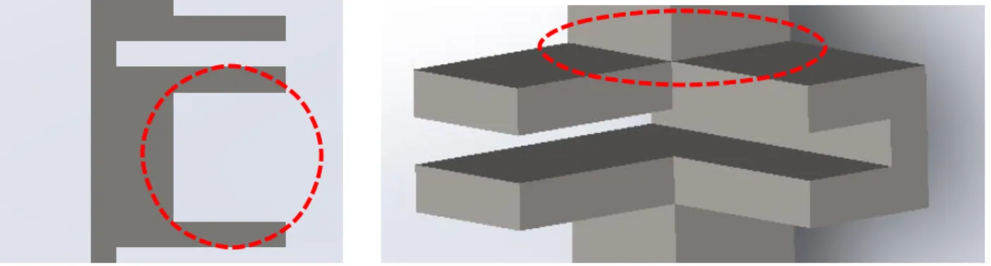
unachievable. Additionally, with cutting tools on mills being round, they cannot make pockets with 90-degree corners in the material, an aspect that all parts in the design feature prominently.
Figure 22. Deep, 90-degree pockets in the front rails highlighted in red
Figure 23. Rounded pocket in back rail
Figure 24. Comparison of old (left) and new (right) front rail designs, displaying newly-rounded
features
Figure 25. Structure design version 2, fully assembled
version of the design could have been accomplishable with FDM, it is likely that the sudden changes in cross sectional area, particularly on the rails, would have been an issue for SLM. Extrusions made to round out surfaces for subtractive manufacturing also help to smoothen these changes in cross-sectional area. A mill can be used to machine all parts of the structure, as none feature sharp internal corners, inaccessible features, fillets on outside edges, deep pockets, or other design aspects that could reduce their manufacturability. This accomplishes the
Chapter 4
CPECK STRUCTURE VIBRATION ANALYSIS
To ensure the CPECK structure will not yield or drastically deform, Finite Element Analysis (FEA) vibration analyses were completed in Ansys Mechanical v18.1. This
encompassed three parts: modal analysis, harmonic analysis, and random vibration analysis. The success criteria, as outlined by the requirements in Appendix A, are that the structure shall deform by less than 0.5 millimeters and have a Factor of Safety (FoS) above 2 at all times during testing. The deformation requirement is derived from the necessity of the kit’s internal PCBs to remain within the structure’s slots. While an individual slot can afford to deform by a maximum
of 3.5 millimeters before the board slips, this does not account for deformation of other areas of the structure. This 0.5-millimeter requirement was chosen to account for the worst possible scenario: deformation of slots on the +Y and –Y faces in opposite directions perpendicular to the boards, while the board itself deforms in the Z-direction.
prediction of the highest stress in ductile materials like ABS and aluminum [63]. Of the other theories available in the ANSYS Mechanical program, maximum principal stress theory is less applicable to ductile materials, but the maximum shear stress or Tresca yield criterion was also considered. Tresca predicts a narrower elastic region and is generally accepted to be more conservative than Von Mises [63]. It was decided that, due to the inherent error assumed when using an analytical model to predict stress and the already conservative FoS of 2, Von Mises would be utilized as it would reduce the likelihood of overdesign.
𝐹𝑜𝑆 = 𝑀𝑎𝑡𝑒𝑟𝑖𝑎𝑙 𝑌𝑖𝑒𝑙𝑑 𝑆𝑡𝑟𝑒𝑛𝑔𝑡ℎ 𝑀𝑎𝑥 𝐸𝑥𝑝𝑒𝑐𝑡𝑒𝑑 𝑆𝑡𝑟𝑒𝑠𝑠 ≥ 2
Equation 1. Factor of Safety
4.1ENVIRONMENT SET-UP
Finite Element Analysis (FEA) works by splitting the object under analysis into a collection of small portions, with each portion called an element, with the apex of each element being a node and the collection of elements called a mesh. Analytical solutions to governing equation are obtained (the specific ones being dependent on what analysis is being completed) within the context of each element, influenced by information from neighboring nodes. Smaller element sizes will achieve a higher level of accuracy in the solution, but exponentially increase the computation time.
geometry being studied (in this case, the 2 millimeter slots supporting the PCBs on the rails) to ensure all geometry is included in the analysis and the solution will converge. Consequently, a maximum element size of 2 millimeters was chosen. As the body being studied was three-dimensional and not solely a surface, linear elements were not applicable and the default quadratic setting (tetrahedral elements) were used in the program-generated mesh.
Figure 26. Smallest feature (PCB slots)
During vibration testing and launch, CubeSat structures are constrained by an enclosure. For launch, this takes the form of a P-POD or other deployer that releases the satellite from the launch vehicle. A similar enclosure, called a Test-POD, is used during testing to attach the CubeSat to the surface of a vibration table.
The SolidWorks Computer Aided Design (CAD) model of the redesigned structure was originally placed in the enclosure model in the analysis environment. However, with more material came more elements that the FEA solver needed to analyze, drastically increasing the computation time from on the order of hours to days. Increasing the element length would reduce the number of elements and consequently the solver run time, but would lead to a less accurate solution. This is because the more localized interactions between components would not be accounted for when the solver analyzes the larger elements, leading to the output deformation and stress values to be lower than what the system would actually see in testing. Again, the element length was also further limited by the smallest feature on the CPECK.
Figure 28 Location of fixed constraints
Figure 29 Pinned supports highlighted in red (4th constrained edge not shown)
In these simulations, the constraints on the backplane are not accurately modeled. In normal operation, the CPECK will have internal boards connected to the backplane, supporting it from excessively moving. These PCBs were removed and analyzed in a separate simulation to make the analyses more efficient, as detailed in section 4.5. While initial versions of these analyses featured the use of ANSYS’s elastic support which restricted movement of a feature in a certain direction, it was later determined that this stopped all movement in the specified axis. This is an unrealistic expectation, and the backplane was left unrestricted to mitigate over-constraining the system. As such, the deformation in the backplane is an overestimation of the actual deformation that is expected to be seen during testing. Therefore, while the unrestricted backplane was included while running vibration simulations, the outputs of its deformation are left out of the presented results. Further, showcasing that the other components of the system can withstand vibration loads coupled with the additional stress from the effects of overestimation of vibration in the backplane, ensures the system will survive normal loadings.
The damping, or decay of the amplitude of vibration, of a system is dependent on a system’s material and geometry. While it is necessary to assign a value for this damping during
analysis simulations, this value can only be accurately obtained through testing. Through research of vibration tests run on CubeSats structures with similar geometry, it has been
𝜁 = 1 2 × 𝑄
Equation 2 Relationship of damping ratio to Q-factor
The Q-factor is a way of describing a system’s oscillation tendency. Larger Q-factors correspond with a system’s tendency to continue oscillating for many cycles before stopping,
whereas low Q-factor systems tend to cease oscillating after relatively few cycles. In general, systems with higher Q-factors will have higher stress and deformation as they are more likely to exhibit resonant behavior. Using equation 2, the Q-factor for the structure was approximated as 250 for AlSi10Mg, 62.5 for Al-6061, and 28.6 for the ABS one. These values match well with the structures’ expected behaviors as metal structures have a higher propensity to vibrate due to their tightly-packed crystal lattice molecular structure, and polymers tend to dampen oscillations due to their semi-crystalline, partially amorphous molecular structure [67].
4.2MODAL ANALYSIS
Modal analysis was done to determine the normal modes of the system. Normal modes are patterns of motion of a system that occur at its natural frequencies, which are the frequencies that a system tends to oscillate at under sinusoidal loading in the absence of a dampening force. The outcome of this analysis is a set of frequencies in which resonance, or the rapid
amplification of response to an input oscillating load, could occur. Due to a modal analysis’
theoretical nature as the normal modes are derived from the geometry and material of the system and not from loading conditions, this can only be done through analysis and cannot be
In an ideal system, the lowest normal mode would occur at a frequency above the expected loading of the system so the possibility of resonance could not possibly occur. However, this is only valid in theory as it is difficult to achieve balance between stiffness and dampening in both material and system properties while adhering to the weight and size constraints provided by the CubeSat standard. A system’s resonant frequencies can be changed
in five main ways [68]:
1. Adding stiffness increases the natural frequency 2. Adding mass decreases the natural frequency
3. Increasing damping reduces the peak response but widens the response range 4. Decreasing damping increases the peak response but narrows the response range 5. Reducing forcing amplitudes reduces response at resonance
Some of these methods can counteract each other, such as how using a stiffer material will likely add mass to the system. Dampening is difficult to change without adjusting the design, which could lead to a violation of other requirements. Reduction in forcing amplitudes is not an option as the loads are typical of what a satellite will experience during launch, and therefore must be tested at the same level.
Consequently, the modal analysis is conducted on the unaltered structure at a range of 0-2100 Hz. This range is based off “NASA General Environmental Standards: Goddard
spaceflight industry as its testing envelope is as or more rigorous than all launch vehicles currently on the market. The results from the modal analysis are shown in table 10.
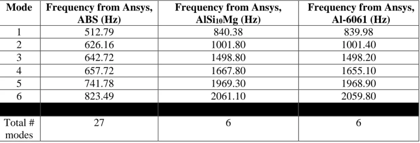
Table 10. First 6 normal modes of CPECK structure for varying materials
Mode Frequency from Ansys,
ABS (Hz)
Frequency from Ansys, AlSi10Mg (Hz)
Frequency from Ansys, Al-6061 (Hz)
1 512.79 840.38 839.98
2 626.16 1001.80 1001.40
3 642.72 1498.80 1498.20
4 657.72 1667.80 1655.10
5 741.78 1969.30 1968.90
6 823.49 2061.10 2059.80
Total # modes
27 6 6
As expected, the more rigid, low damping, vibration resistant metal structures have few total modes as it is more difficult to induce resonance in them. Further, the frequencies their modes occur at are very similar due to the similarities in molecular composition and mechanical properties of Al-6061 and AlSi10Mg. The ABS structure has a high number of total modes which tend to be closer together than the one that occur in the metal structures. This is consistent with predictions as the weaker ABS structure is more likely to experience resonance at lower
loadings. Results from these modal analyses identify potential areas of resonance and are incorporated in harmonic and random vibration analyses to help simulate testing.
4.3HARMONIC VIBRATION ANALYSIS
because the loading is sinusoidal and the test is done over a range of frequencies. It should be noted that constant acceleration in a sinusoidal context refers to maintaining a constant value for the maximum acceleration amplitude in a certain direction. Sinusoidal loading inherently means non-constant driving as the system accelerates in one direction, slows down and reverses
direction, and then accelerates in the direction opposite to which it started. This is the basis of harmonic vibration testing as the test fixture is moving back and forth rapidly, but sustaining the same magnitude at peak acceleration in each direction.
Since modal investigations cannot be completed outside of an analysis environment, harmonic sweeps are completed during testing to identify a system’s normal modes. Harmonic loadings are drastically lower in amplitude than those seen in random vibration tests, and as such are not expected to cause failure or large deformations. However, these low intensity
acceleration loadings can be used to identify areas of resonance as the system’s acceleration
response to the input will spike at modes. The maximum response from testing data will be used to experimentally determine the system’s Q-factor and damping ratio, so this harmonic analysis
will identify where this peak is expected to be seen. Further, these analyses are useful in comparison to one another. During testing, a system is subjected to a harmonic test before and after a higher intensity random vibration test in each axis. The initial sweep characterizes the system’s pre-random vibration response, the second sweep characterizes the system’s
Harmonic analysis for the structure is done in accordance to NASA GEVS. The vibration inputs are values of acceleration that inform the simulation software (or shaker table during testing) how to drive the system. These accelerations are applied at both the pinned and fixed supports. The required testing levels for harmonic analyses are outlined in table 11 and represented visually in figure 31.
Table 11. NASA GEVS harmonic testing levels for structures under 22.7 kilograms [69]
Frequency Range (Hz)
Acceleration Amplitude (g) Acceleration Amplitude (mm/s2)
20-2000 0.5 4903.325
Figure 31. Harmonic analysis graph
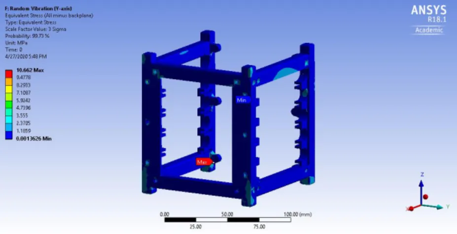
As shown in figures 32 and 33 and table 12, the maximum stresses and deformations seen in all structures are relatively minimal and are expected to be orders of magnitude less than what will be seen in random vibration analyses. Further, the maximum acceleration response for all structures was seen in the Y-axis. This provides a reference point for where resonance should occur during testing. The axis of maximum stress was inconsistent across the structures. It should be noted, the deformation and stress pictures in this thesis present all parts besides the backplane.
0 0.2 0.4 0.6
0 500 1000 1500 2000
A cc eler atio n ( g 's ) Frequency (Hz)
The backplane is part of the structure and is included during the analysis, but was chosen to be hidden in presenting the results to better showcase areas of high deformation.
Table 12. Deformation and strength of structures during harmonic vibration
Structure Material
Structure Max Deformation
(mm)
Axis of Max Deformation
Structure Max Stress (MPa)
Axis of Max Stress
Structure FoS
Backplane Max Stress (MPa)
Backplane FoS
ABS 0.0018 Y 0.5090 Y 73.8200 0.2820 1347.5200
AlSi10Mg 0.0007 Y 0.6590 X 424.8990 0.6070 626.0300 Al-6061 0.0008 Y 0.7170 Y 384.9400 0.5840 650.6900
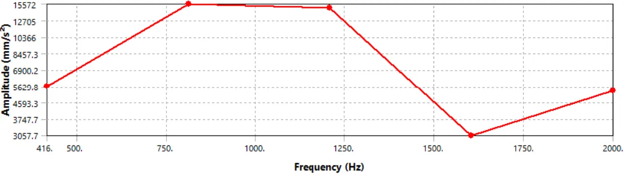
Figure 34. Maximum acceleration response for the ABS structure occurs at 812 Hz
Figure 35. Maximum acceleration response for the AlSi10Mg structure occurs at 1604 Hz
Figure 36. Maximum acceleration response for the Al-6061 structure occurs at 1604 Hz
![Table 1. Classification of satellites by average mass, cost, and development time [6,7]](https://thumb-us.123doks.com/thumbv2/123dok_us/8219974.2179324/17.918.102.811.688.904/table-classification-satellites-average-mass-cost-development-time.webp)
![Table 6. Average fasteners/components required to be removed for PCB de-integration [42]](https://thumb-us.123doks.com/thumbv2/123dok_us/8219974.2179324/37.918.145.779.604.995/table-average-fasteners-components-required-removed-pcb-integration.webp)
![Table 11. NASA GEVS harmonic testing levels for structures under 22.7 kilograms [69]](https://thumb-us.123doks.com/thumbv2/123dok_us/8219974.2179324/67.918.103.807.433.767/table-nasa-gevs-harmonic-testing-levels-structures-kilograms.webp)
![Table 13. NASA GEVS random vibration testing levels for structures under 22.7 kilograms [69]](https://thumb-us.123doks.com/thumbv2/123dok_us/8219974.2179324/71.918.108.815.729.863/table-nasa-random-vibration-testing-levels-structures-kilograms.webp)
![Figure 37. Graph of random vibration testing levels, ASD vs frequency [69]](https://thumb-us.123doks.com/thumbv2/123dok_us/8219974.2179324/72.918.197.723.111.431/figure-graph-random-vibration-testing-levels-asd-frequency.webp)